Operation and parts Manual SERVPRO R ® Whisperwatt™ Series MODEL DCA20SPXU4F 60Hz GENERATOR (ISUZU 4LE2T DIESEL ENGINE) PARTS LIST NO. M1871300404 NOTICE This generator is manufactured for SERVPRO® by Multiquip, Inc. Revision #0 (07/16/14) THIS MANUAL MUST ACCOMPANY THE EQUIPMENT AT ALL TIMES.
proposition 65 warning Diesel engine exhaust and some of page 2 — dca20SPXU4F servpro™ • operation and Parts manual — rev.
Reporting Safety Defects If you believe that your vehicle has a defect that could cause a crash or could cause injury or death, you should immediately inform the National Highway Traffic Safety Administration (NHTSA) in addition to notifying Multiquip Inc. at 1-800-421-1244. If NHTSA receives similar complaints, it may open an investigation, and if it finds that a safety defect exists in a group of vehicles, it may order a recall and remedy campaign.
Table of Contents DCA20SPXU4F 60 Hz Generator Proposition 65 Warning............................................ 2 Reporting Safety Defects.......................................... 3 Table Of Contents..................................................... 4 Safety Information............................................... 6-11 Specifications......................................................... 12 Dimensions............................................................. 13 Installation....................
notes dca20SPXU4F servpro™ • operation manual — rev.
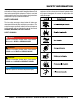
Safety Information Do not operate or service the equipment before reading the entire manual. Safety precautions should be followed at all times when operating this equipment. Failure to read and understand the safety messages and operating instructions could result in injury to yourself and others. Potential hazards associated with the operation of this equipment will be referenced with hazard symbols which may appear throughout this manual in conjunction with safety messages.
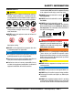
Safety Information general SaFetY caUtion never operate this equipment without proper protective clothing, shatterproof glasses, respiratory protection, hearing protection, steel-toed boots and other protective devices required by the job or city and state regulations. never operate this equipment when not feeling well due to fatigue, illness or when under medication. never operate this equipment under the influence of drugs or alcohol.
Safety Information engine SaFetY danger The engine fuel exhaust gases contain poisonous carbon monoxide. This gas is colorless and odorless, and can cause death if inhaled. The engine of this equipment requires an adequate free flow of cooling air. never operate this equipment in any enclosed or narrow area where free flow of the air is restricted. If the air flow is restricted it will cause injury to people and property and serious damage to the equipment or engine.
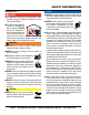
Safety Information FUel SaFetY danger do not start the engine near spilled fuel or combustible fluids. Diesel fuel is extremely flammable and its vapors can cause an explosion if ignited. Make sure the hitch and coupling of the towing vehicle are rated equal to, or greater than the trailer “gross vehicle weight rating.” alWaYS inspect the hitch and coupling for wear. never tow a trailer with defective hitches, couplings, chains, etc.
Safety Information electrical SaFetY danger do not touch output terminals during operation. Contact with output terminals during operation can cause electrocution, electrical shock or burn. The electrical voltage required to operate the generator can cause severe injury or even death through physical contact with live circuits. Turn generator and all circuit breakers OFF before performing maintenance on the generator or making contact with output terminals.
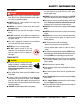
Safety Information If the battery liquid (dilute sulfuric acid) comes into contact with clothing or skin, rinse skin or clothing immediately with plenty of water. emiSSionS inFormation If the battery liquid (dilute sulfuric acid) comes into contact with eyes, rinse eyes immediately with plenty of water and contact the nearest doctor or hospital to seek medical attention.
Specifications Model Type Table 1. Generator Specifications DCA20SPXU4F Revolving field, self ventilated, open protected type synchronous generator Star with Neutral 1Ø 22.0 kW (27.5 kVA) 20 kW (25 kVA) Armature Connection Phase Standby Output Prime Output 1Ø Voltage (L-L/L-N) 120/240 Voltage Selector Switch at 1Ø 240/120 Power Factor 1.0 Frequency 60 Hz Speed 1800 rpm Aux. AC Power Single Phase, 60 Hz Aux. Voltage/Output 4.8 Kw (2.4 kW x 2) Dry Weight 1,797 lbs. (815 kg)) Wet Weight 2,138 lbs.
Dimensions 3,240 lbs. (1,470 kg) R Like it never even happened. 20 Figure 1. Dimensions Table 3. Dimensions Reference Letter Dimension in. (mm) Reference Letter Dimension in. (mm) A 22.91 (582) E 22.36 (568) B 21.73 (552) F 71.65 (1,820) C 22.36 (568) G 49.61 (1,260) D 26.38 (670) H 31.10 (790) dca20SPXU4F servpro™ • operation manual — rev.
Installation GENERATOR GROUND LUG GROUND ROD FOR EARTH GROUND. CONNECT TO BUILDING GROUND IF APPLICABLE GROUND CABLE REFERENCE NEC 250-83 (C) M 8’ ( ) UM M INI Figure 2. Typical Generator Grounding Application page 14 — dca20SPXU4F servpro™ • operation and Parts manual — rev.
Installation Outdoor Installation Mounting Install the generator in a area that is free of debris, bystanders, and overhead obstructions. Make sure the generator is on secure level ground so that it cannot slide or shift around. Also install the generator in a manner so that the exhaust will not be discharged in the direction of nearby homes. The generator must be mounted on a solid foundation (such as concrete) and set firmly on the foundation to isolate vibration of the generator when it is running.
General Information Generator Open Delta Excitation System This generator (Figure 3) is designed as a high quality portable (requires a trailer for transport) power source for telecom sites, lighting facilities, power tools, submersible pumps and other industrial and construction machinery. Each generator is equipped with the state of the art “OpenDelta” excitation system. The open delta system consist of an electrically independent winding wound among stationary windings of the AC output section.
Major Components 1 2 R Like it never even happened. 20 3 8 7 6 5 4 9 R ECU Intergrated Gauge Control Low Oil Pressre High temp. Over Crank Over Speed Engine Started 10 11 Table 4. Generator Major Components ITEM NO.
trailer Major Components 1 2 3 4 5 10 9 6 8 7 Figure 4. Trailer Components Figure 4 shows the location of the trailer components. The function of each component is described below: 1. Fuel Filler Neck/Tank — This generator may have an external trailer mounted fuel tank. Remove fuel tank cap to add fresh clean No. 2 diesel fuel. External fuel tank capacity is 41 gallons (155 liters). 2. Tongue Jackstand — Use this jackstand to support the tongue when attaching the generator to a towing vehicle 3.
notes dca20SPXU4F servpro™ • operation manual — rev.
ENGINE/Generator Control Panel 2 3 13 R ECU Intergrated Gauge Control Low Oil Pressre 4 15 High temp. Over Crank Over Speed R F Engine Started 14 7 ECU Intergrated Gauge Control Low Oil Pressre High temp. Over Crank 9 5 Over Speed Engine Started 8 10 6 11 12 Figure 5. Engine/Generator Control Panel The definitions below describe the controls and functions of the Engine/Generator Control Panel (Figure 5). 1. Gauge Unit Assembly — This assembly houses the various engine monitoring gauges.
ENGINE/Generator Control Panel 4. Frequency Meter — Indicates the output frequency in hertz (Hz). Normally 60 Hz 5. AC Ammeter — Indicates the amount of current the load is drawing from the generator per leg selected by the ammeter phase-selector switch. 6. AC Voltmeter — Indicates the output voltage present at the U,O and V Output Terminal Lugs. 7. Fuel Leak Detected Alarm Lamp — This lamp when ON indicates that fluids in the containment area have reach a high level. 8.
OUTPUT TERMINAL PANEL FAMILIARIZATION Output Terminal Panel Output Terminal Familiarization The Output Terminal Panel (Figure 6) shown below is located on the right-hand side (left from control panel) of the generator. Lift up on the cover to gain access to receptacles and terminal lugs. The “Output Terminal Panel ” (Figure 6) is provided with the following: Two 120/240 output receptacles @ 50 amps Two Aux.
OUTPUT TERMINAL PANEL FAMILIARIZATION 120 VAC GFCI Receptacles There are two 120 VAC, 20 amp GFCI (Duplex Nema 5-20R) receptacles provided on the output terminal panel. These receptacles can be accessed in any voltage change-over board configuration. Each receptacle is protected by a 20 amp circuit breaker. These breakers are located directly above the GFCI receptacles. Remember the load output (current) of both GFCI receptacles is dependent on the load requirements of the U, V, and W output terminal lugs.
OUTPUT TERMINAL PANEL FAMILIARIZATION Connecting Loads Over Current Relay Loads can be connected to the generator by various methods, output terminal lugs, camlocks or the convenience receptacles (Figure 11). Make sure to read the operation manual before attempting to connect a load to the generator. An over current relay (Figure 12) is connected to the main circuit breaker. In the event of an overload, both the circuit breaker and the over current relay may trip.
Load Application Single Phase Load NOTICE Always be sure to check the nameplate on the generator and equipment to insure the wattage, amperage, frequency, and voltage requirements are satisfactorily supplied by the generator for operating the equipment. Motors and motor-driven equipment draw much greater current for starting than during operation. Generally, the wattage listed on the nameplate of the equipment is its rated output.
ac ammeter gauge reading how to Read the ac ammeter gauge The AC ammeter gauge is controlled by the AC ammeter change-over switch. This switch is located on the control panel and does not effect the generator output. It is provided to help observe how much power is being supplied, produced at the UVO terminal lugs.
OUTPUT TERMINAL PANEL CONNECTIONS UOV Terminal Output Voltages 1Ø-120 Output Terminal Voltage Voltage 240/120V outout voltages can be obtained using the output terminal lugs. 1. Connect the load wires to the output terminal lugs as shown in Figure 16. The voltage regulator (VR), Figure 15 allows the user to increase or decrease the selected voltage. BLACK WHITE RED U O V GREEN 1Ø-240 Output Terminal Voltage 1. Connect the load wires to the output terminal lugs as shown in Figure 14.
OUTPUT TERMINAL PANEL CONNECTIONS Circuit Breakers To protect the generator from an overload, a 3-pole, 90 amp, main circuit breaker is provided to protect the U,O, and V Output Terminals from overload. In addition two single-pole, 20 amp GFCI circuit breakers are provided to protect the GFCI receptacles from overload. Two 50 amp load circuit breakers have also been provided to protect the auxiliary receptacles from overload.
inspection/SETUP Refueling Procedure: 5. NEVER overfill fuel tank — It is important to read the fuel gauge when filling trailer fuel tank. DO NOT wait for fuel to rise in filler neck (Figure 21). WARNING Diesel fuel and its vapors are dangerous to your health and the surrounding environment. Avoid skin contact and/or inhaling fumes. 3. Level Tanks — Make sure fuel cells are level with the ground. Failure to do so will cause fuel to spill from the tank before reaching full capacity (Figure 19).
inspection/SETUP Day-to-day addition of coolant is done from the recovery tank. When adding coolant to the radiator, DO NOT remove the radiator cap until the unit has completely cooled. See Table 8 for engine, radiator, and recovery tank coolant capacities. Make sure the coolant level in the recovery tank is always between the “H” and the “L” markings. Table 8. Coolant Capacity Engine and Radiator 2.3 gal (8.
inspection/SETUP Battery Cable Installation NOTICE ALWAYS be sure the battery cables (Figure 24) are properly connected to the battery terminals as shown below. The red cable is connected to the positive terminal of the battery, and the black cable is connected to the negative terminal of the battery. If the battery cable is connected incorrectly, electrical damage to the generator will occur. Pay close attention to the polarity of the battery when connecting the battery.
GENERATOR START-UP PROCEDURE (MANUAL mode) Before Starting 2. Place the engine speed switch (Figure 28) in the LOW (down) position. CAUTION The engine’s exhaust contains harmful emissions. ALWAYS have adequate ventilation when operating. Direct exhaust away from nearby personnel. WARNING NEVER manually start the engine with the main, GFCI or auxiliary circuit breakers in the ON (closed) position. 1. Place the main, G.F.C.I., and aux.
GENERATOR START-UP PROCEDURE (manual MODE) 7. If the engine is running smoothly, place the engine speed switch (Figure 31) in the HIGH (up) position. Figure 31. Engine Speed Switch (High) 8. The generator’s frequency meter (Figure 32) should be displaying the 60 cycle output frequency in HERTZ. Figure 35. Ammeter (No Load) 12. The engine oil pressure gauge (Figure 36) will indicate the oil pressure of the engine. Under normal operating conditions the oil pressure is approximately 50 psi. (345 kPa).
GENERATOR START-UP PROCEDURE (manual MODE) 15. Place the main, GFCI, and aux. circuit breakers in the ON position (Figure 39). Figure 39. Main, Aux. and GFCI Circuit Breakers (ON) 16. Observe the generator’s ammeter (Figure 40) and verify it reads the anticipated amount of current with respect to the load. The ammeter will only display a current reading if a load is in use. Figure 40. Ammeter (Load) 17. The generator will run until manually stopped or an abnormal condition occurs.
GENERATOR START-UP PROCEDURE (AUTO MODE) DANGER Before connecting this generator to any building’s electrical system, a licensed electrician must install an isolation (transfer) switch. Serious damage to the building’s electrical system may occur without this transfer switch. NOTICE When connecting the generator to a isolation (transfer) switch, ALWAYS have power applied to the generator’s internal battery charger. This will ensure that the engine will not fail due to a dead battery.
GENERATOR SHUT-DOWN PROCEDURES WARNING NEVER stop the engine suddenly except in an emergency. Emergency Shutdown Procedure 1. Push the Emergency Stop Pushbutton Switch (Figure 44). Normal Shutdown Procedure To shutdown the generator, use the following procedure: 1. Place both the MAIN, GFCI and LOAD circuit breakers as shown in Figure 42 to the OFF position. Figure 44.
Maintenance Table 10.
Maintenance NOTICE Before inspecting generator, check that the Auto/ Manual switch is in the OFF/RESET position, and place all circuit breakers in the OFF position. Allow sufficient time for adequate cooling. When ready to restart, complete all steps in the Generator Startup Procedure section of this manual. General Inspection Prior to each use, the generator should be cleaned and inspected for deficiencies. Check for loose, missing or damaged nuts, bolts or other fasteners.
Maintenance Fuel Tank Inspection Check Oil Level In addition to cleaning the fuel tank, the following components should be inspected for wear: Check the crankcase oil level prior to each use, or when the fuel tank is filled. Insufficient oil may cause severe damage to the engine. Make sure the generator is level. The oil level must be between the two notches on the dipstick as shown in Figure 17. Rubber Suspension — look for signs of wear or deformity due to contact with oil.
Maintenance Radiator Cleaning The radiator (Figure 47) should be sprayed (cleaned) with a high pressure washer when excessive amounts of dirt and debris have accumulated on the cooling fins or tube. When using a high pressure washer, stand at least 5 feet (1.5 meters) away from the radiator to prevent damage to the fins and tube. The purpose of these receptacles is to provide power via commercial power to the jacket water heater and internal battery charger.
Trailer Maintenance TRAILER MAINTENANCE The following trailer maintenance guidelines are intended to assist the operator in preventive maintenance. Adjustable Channel Your trailer may be equipped with an adjustable channel (Figure 49) that allows the coupler to be raised or lowered to a desired height. Periodically check the channel bolts for damage or loosening. NOTICE When replacing channel mounting hardware (nuts, bolts and washers), NEVER substitute substandard hardware.
Trailer Maintenance DANGER NEVER crawl under the trailer unless it is on firm and level ground and resting on properly placed and secured jackstands. The possibility exists of the trailer falling thus causing equipment damage and severe bodily harm even death! Leaf Suspension The leaf suspension springs and associated components (Figure 51) should be visually inspected every 6,000 miles for signs of excessive wear, elongation of bolt holes, and loosening of fasteners.
Trailer GUIDELINES The following guidelines are intended to assist the operator in the operation and handling of a trailer. Shift your automatic transmission into a lower gear for city driving. Safety precautions should be followed at all times when operating a trailer. Failure to read, understand and follow the safety guidelines could result in injury to yourself and others. Loss of control of the trailer or tow vehicle can result in death or serious injury.
Trailer GUIDELINES driving conditionS When towing a trailer, you will have decreased acceleration, increased stopping distance, and increased turning radius (which means you must make wider turns to keep from hitting curbs, vehicles, and anything else that is on the inside corner). In addition, you will need a longer distance to pass, due to slower acceleration and increased length. Be alert for slippery conditions.
Trailer GUIDELINES inoperaBle BrakeS, ligHtS or mirrorS Be sure that the brakes and all of the lights on your trailer are functioning properly before towing your trailer. Check the trailer taillights by turning on your tow vehicle headlights. Check the trailer brake lights by having someone step on the tow vehicle brake pedal while you look at trailer lights. Do the same thing to check the turn signal lights. See Trailer Wiring Diagram section in this manual.
Trailer GUIDELINES To determine the “empty” or “net” weight of your trailer, weigh it on an axle scale. To find the weight of the trailer using an axle scale, you must know the axle weights of your tow vehicle without the trailer coupled. Some of the trailer weight will be transferred from the trailer to the tow vehicle axles, and an axle scale weighs all axles, including the tow vehicle axles. G VIN TA VIN TAG Figure B.
Trailer GUIDELINES SaFetY cHainS If the coupler connection comes loose, the safety chains can keep the trailer attached to the tow vehicle. With properly rigged safety chains, it is possible to keep the tongue of the trailer from digging into the road pavement, even if the coupler-to-hitch connection comes apart. JackStand A device on the trailer that is used to raise and lower the coupler. The jack is sometimes called the “landing gear” or the “tongue jack”.
Trailer GUIDELINES Warning Lower the trailer (Figure D) until the coupler fully engages the hitch ball. A worn, cracked or corroded hitch ball can fail while towing and may result in death or serious injury. 2-INCH TRAILER COUPLER Before coupling trailer, inspect the hitch ball for wear, corrosion and cracks. TOW VEHICLE Replace worn or damaged hitch ball. 2-INCH BALL Warning A loose hitchball nut can result in uncoupling, leading to death or serious injury.
Trailer GUIDELINES Attaching Safety Chain Backup Lights (place tow vehicle gear shift in reverse). Visually inspect the safety chains and hooks for wear or damage. Replace worn or damaged safety chains and hooks before towing. Turn Signals (activate tow vehicle directional signal lever). Attach the safety chains so that they: • Cross underneath the coupler. See Figure E.
Trailer GUIDELINES pintle HitcH coUpler A pintle eye coupler (Figure F) connects to a pintle-hook hitch that is located on or under the rear bumper of the tow vehicle. This system of coupling a trailer to a tow vehicle is sometimes referred to as a “lunette eye, tow ring or G.I. hitch.
Trailer GUIDELINES Raise the bottom surface of the coupler to be above the top of the pintle hitch hook. Use the tongue jackstand to support the trailer tongue. Wood or concrete blocks may also be used. Warning Lower the trailer so that its entire tongue weight is held by the hitch. Raise the jackstand to a height where it will not interfere with the road. tire SaFetY A defective pintle hitch not properly fastened can result in uncoupling, leading to death or serious injury.
Trailer GUIDELINES wrench, use a lug wrench (from your tow vehicle) and tighten the nuts as much as you can. Then have a service garage or trailer dealer tighten the lug nuts to the proper torque. Warning Metal creep between the wheel rim and lug nuts will cause rim to loosen and could result in a wheel coming off, leading to death or serious injury. Tighten lug nuts before each tow. Lug nuts are also prone to loosen after first being assembled.
Trailer GUIDELINES Step 2. Determine the weight of the equipment being loaded on the tow vehicle. That weight may not safely exceed the available equipment load capacity. The trailer’s Tire Information Placard is attached adjacent to or near the trailer’s VIN (Certification) label at the left front of the trailer (See Figure I). along with other care and maintenance activities, can also: Locate the statement, “The combined weight of occupants and cargo should never exceed XXX lbs.
Trailer GUIDELINES next number: This two-digit number is the wheel or rim diameter in inches. If you change your wheel size, you will have to purchase new tires to match the new wheel diameter. in the tire. In general, the greater the number of plies, the more weight a tire can support. Tire manufacturers also must indicate the materials in the tire, which include steel, nylon, polyester, and others. next number: This two- or three-digit number is the tire’s load index.
Trailer GUIDELINES Tires for light trucks have other markings besides those found on the sidewalls of passenger tires. lt: The “LT” indicates the tire is for light trucks or trailers. St: An “ST” is an indication the tire is for trailer use only. max. load dual kg (lbs) at kPa (psi) Cold: This information indicates the maximum load and tire pressure when the tire is used as a dual, that is, when four tires are put on each rear axle (a total of six or more tires on the vehicle). max.
Trailer GUIDELINES Wheel rims If the trailer has been struck, or impacted, on or near the wheels, or if the trailer has struck a curb, inspect the rims for damage (i.e. being out of round); and replace any damaged wheel. Inspect the wheels for damage every year, even if no obvious impact has occurred. 3.
Trailer GUIDELINES Figure L. Trailer to Tow Vehicle Wiring Diagram dca20SPXU4F servpro™ • operation manual — rev.
Troubleshooting Diagnostics The engine controller of this generator diagnoses problems that arise from the engine control system and the engine itself. Press the diagnostic button on the diagnostic panel (Figure 52) to determine if an engine malfunction has occurred. DIAGNOSTIC LAMP DIAGNOSTIC BUTTON ON DIAGNOSTIC SWITCH OFF FUEL PUMP SWITCH ON 6. The following will occur: The diagnostic lamp will start blinking with a pattern associated with the fault 3 times at an interval of 2.4 seconds.
Troubleshooting generator Practically all breakdowns can be prevented by proper handling and maintenance inspections, but in the event of a breakdown, use Table 11 shown below for diagnosis of the Generator. If the problem cannot be remedied, consult our company’s business office or service plant. Symptom No Voltage Output Low Voltage Output High Voltage Output Circuit Breaker Tripped Table 11.
Troubleshooting engine troubleshooting (engine) Symptom Engine will not start or start is delayed, although engine can be turned over. At low temperatures engine will not start. Engine fires but stops soon as starter is switched off. Engine stops by itself during normal operation. Low engine power, output and speed. Possible Problem Solution No Fuel reaching injection pump? Add fuel. Check entire fuel system. Defective fuel pump? Replace fuel pump.
Troubleshooting engine (continued) troubleshooting (engine) - continued Symptom Low engine power output and low speed, black exhaust smoke. Engine overheats. Possible Problem Solution Air filter blocked? Clean or replace air filter. Incorrect valve clearances? Adjust valves per engine specification. Malfunction at injector? See engine manual. Too much oil in engine crankcase? Drain off engine oil down to uppermark on dipstick.
Generator Wiring Diagram page 62 — dca20SPXU4F servpro™ • operation and Parts manual — rev.
Engine Wiring Diagram dca20SPXU4F servpro™ • operation manual — rev.
battery charger Wiring Diagram BLACK 14 AWG. LINE (L)120VAC INPUT A WHITE 14 AWG. NEUTRAL (N) B 3 1 2 GREEN 14 AWG. GROUND (G) AC POWER CORD 3 BL K WH T GR N TO CHASSIS GROUND DC 5 B 4 12 0V AC IN PU T BA CH TTE AR RY GE R DC+ TO STARTER “B” TERMINAL 7.5 AMP FUSE 7.5 AMP FUSE A 4 1 2 120 VAC INPUT, INSERT EXTERNAL POWER CORD HERE. NOTES: 1 NEMA 5-15, 15A, 120 VAC, P/N EE6176 (HBL5278C/HUBBLE RECEPTACLE). 2 RECEPTACLE IS MOUNTED ON OUTPUT TERMINAL PANEL ASSY.
jacket water heater Wiring Diagram BLACK 14 AWG. LINE (L)120VAC INPUT WHITE 14 AWG. NEUTRAL (N) A B 3 1 2 4 GREEN 14 AWG. GROUND (G) BLOCK HEATER (P/N 44558) BLACK 14 AWG. LINE (L)120VAC INPUT WHITE 14 AWG. NEUTRAL (N) 3 TEMP. SWITCH 120 VAC HEATING ELEMENT GREEN 14 AWG. GROUND (G) B GROUND A 4 1 2 120 VAC INPUT, INSERT EXTERNAL POWER CORD HERE. NOTES: 1 NEMA 5-15, 15A, 120 VAC, P/N EE6176 (HBL5278C/HUBBLE RECEPTACLE). 2 RECEPTACLE IS MOUNTED ON OUTPUT TERMINAL PANEL ASSY.
Explanation of Code in Remarks Column The following section explains the different symbols and remarks used in the Parts section of this manual. Use the help numbers found on the back page of the manual if there are any questions. NOTICE The contents and part numbers listed in the parts section are subject to change without notice. Multiquip does not guarantee the availability of the parts listed. Sample partS liSt no. 1 2% 2% 3 4 part no. part name QtY. remarkS 12345 BOLT .....................1 .....
Suggested Spare Parts DCA20spxu4f WHISPERWATT GENERATOR with ISUZU 4LE2T DIESEL ENGINE 1 to 3 units Qty. P/N Description 3............P822769................AIR FILTER (SAFTEY) 3............PMAF25436...........ELEMENT, AIR, PRIMARY (INNER) 3............2944566410...........ELEMENT, OIL FILTER 5............8982402790...........ELEMENT, FUEL FILTER (MAIN) 5............8982402800...........ELEMENT, FUEL FILTER (PRE) 5............8981731650...........KIT, FEED PUMP FILTER 3............8980490340...........
GENERATOR ASSY. page 68 — dca20SPXU4F servpro™ • operation and Parts manual — rev.
GENERATOR ASSY. NO. PART NO.
CONTROL BOX 1 ASSY. page 70 — dca20SPXU4F servpro™ • operation and Parts manual — rev.
CONTROL BOX 1 ASSY. NO. 1 1-1 1-2 2 3 4 4A 5 8 9 10 10A 10B 10C 11 13 13A 13B 14 15 18 19 20 21 22 23 24 27 28 29 30 31 32 33 39 39A 53 54 64 65 66 67 68 PART NO.
CONTROL BOX 2 ASSY. page 72 — dca20SPXU4F servpro™ • operation and Parts manual — rev.
CONTROL BOX 2 ASSY. NO. 6 6A 7 12 12A 16 17 18 25 26 34 35 35A 36 36A 37 37A 38 38A 40 41 42 43 44 45 46 47 47A 48 49 50 50A 51 52 55 56 57 58 58A 59 60 61 62 63 64 65 66 PART NO.
engine AND Radiator ASSY. page 74 — dca20SPXU4F servpro™ • operation and Parts manual — rev.
engine AND Radiator ASSY. NO. 1 1A 2 3 4 5 6 7 8 9 10 11 12 13 13-1 14 15 16 17 18 19 19A 19B 20 21 21A 22 23 24 25 26 26A 27 28 29 30 31 32 33 34 35 36 37 PART NO.
engine AND Radiator ASSY. (continued) page 76 — dca20SPXU4F servpro™ • operation and Parts manual — rev.
engine AND Radiator ASSY. (continued) NO. 38 39 40 41 42 43 44 45 46 47 48 49 50 51 52 53 54 PART NO. 0605511395 0603306395 0602021070 0269200600 0802081403D 0802081104 M1317100004 0199100215 Y0199900520 0193601100 0605515189 011008020 1622014103 011206020 0802011104 0150000018 0605515189 PART NAME QTY. REMARKS VALVE 1 HOSE JOINT 1 CAP 1 DRAIN HOSE 1 RESERVE TANK ................................................1................REPLACES P/N M9300000003 CAP, RESERVE TANK ....................................
output terminal ASSY. NOTICE When ordering any painted panel SERVPRO® must add the digit 2 after the part number, this will indicate that the panel color is WHITE. Once the panel has been received it should be painted Sherwin-Williams (SERVPRO® Green), Product PGS 860083, color Pantone 368C page 78 — dca20SPXU4F servpro™ • operation and Parts manual — rev.
output terminal ASSY. NO. 1 2 3 4 5 6 7 8 9 10 11 11A 11B 12 12A 13 13A 13B 13C 14 15 16 17 18 19 20 21 22 23 24 24-1 25 26 27 28 28A 29 30 31 32 33 34 35 PART NO.
battery ASSY. page 80 — dca20SPXU4F servpro™ • operation and Parts manual — rev.
battery ASSY. NO. PART NO. 1 0602220185 2 M9310500014 3 M9103000304 4 0602220920 5 M1346400004 6 M2346900304 7 8 0016910025 8A 0040510000 9 011208025 9A 0040508000 PART NAME QTY. REMARKS BATTERY 1 BATTERY SHEET 1 BATTERY BAND 1 BATTERY BOLT SET 2 BATTERY CABLE 1 BATTERY CABLE 1 CABLE ...............................................................1................PURCHASE LOCALLY HEX. HEAD BOLT 1 TOOTHED WASHER 1 HEX. HEAD BOLT ..............................................1................
muffler ASSY. page 82 — dca20SPXU4F servpro™ • operation and Parts manual — rev.
muffler ASSY. NO. 1 2 3 4 5 6 7 7A 8 9 9A 10 11 12 13 14 15 16 17 18 19 20 21 PART NO. 8982353890 M1331400103 0016908020 8982284330 0016910025 8982103230 0037908000 0041208000 8973731080 8980435280 8971616070 M1331400204 M1331400304 0016906015 Y0602326066 M1334000703 8973679180 0207108000 M1331400504 M1331400904 M1331401004 Y0272100270 Y0602325051 PART NAME QTY. REMARKS DOC ...................................................................1................REPLACES P/N Y0602330111 DOC BRACKET 1 HEX.
fuel tank ASSY. page 84 — dca20SPXU4F servpro™ • operation and Parts manual — rev.
fuel tank ASSY. NO. 1 1-1 2 3 4 5 6 7 8 9 10 11 12 13 14 15 16 17 18 19 19A 20 20A 21 22 23 24 25 25A 26 27 28 PART NO. M1364000302 0605505070 0605501071 0605516090 7538070 M1363200304 M1365200204 M9310500104 011008020 020108060 0191301200 Y0191300820 Y0191300790 0191301150 0191300900 0191301300 0605515189 M1367700104 011008020 8982369900 8982402790 8982369910 8982402800 8981263320 1096751930 1096300850 Y0017110035 8980682750 8981731650 Y0016906025 Y0222100550 Y0605515340 PART NAME QTY.
trailer ASSY. (TRLR25US) 24 26 17 25 4 15 13 1 21 5 18 19 23 14 9 16 27 6 8 7 2 2 1 3 10 22 28 NOTES: 1 GROUND POINT page 86 — dca20SPXU4F servpro™ • operation and Parts manual — rev.
trailer ASSY. (TRLR25US) NO. 1# 2# 3 4 5 6 7 8# 9 10 12 13 14 15 16 17 18 19 21 22 23 24 25 26 27 28 PART NO. 0205 4001 5065 B 9505 9512 9514 10019 10133 29242 29243 29248 29478 29572 29618 29621 29784 29898 29900 9509 29754 60018 29228 9502 9503 EE45318 29194 PART NAME QTY. REMARKS SCREW, HHC 3/8-16 X 1.0 8 WASHER, FLAT USS 3/8 PLD 16 SCREW, PHP 10-32 X 1/2 2 FENDER, 8 X 30 X 13, DRILLED 2 INSULATOR, WIRING .
battery charger ASSY. 2 3 1 4 4 5 6 7 8 6 7 OUTPUT TERMINAL PANEL COVER 9 10 page 88 — dca20SPXU4F servpro™ • operation and Parts manual — rev.
battery charger ASSY. NO. PART NO. 1 2 EE19824 3$ EE58072 4$ 23284-075 5$ EE58070 6 HBL5369C 7 EE56557 8 OEMAA8 9 HBL5278C 10 7538070 PART NAME QTY. REMARKS SCREW, 10-24 X 1/2".........................................2................OBTAIN LOCALLY CHARGER, BATTERY, TENDER 12V, 5A..........1................INCLUDES ITEMS W/$ CORD, CHARGE SIDE 1 FUSE 7.5 AMP 2 CORD, CHARGE, STARTER SIDE 1 CONNECTOR, 20 AMP ,125V 1 CORD, CAROL 3/C 14 AWG............................ AR...............1PC = 1FT.
jacket water heater ASSY. 7 4 3 5 5 6 2 9 1 5 8 EXISTING DRAIN HOSE RELOCATED TO TEE FITTING 5 7 page 90 — dca20SPXU4F servpro™ • operation and Parts manual — rev.
jacket water heater ASSY. NO. PART NO. 1 2 3 4 5 6 7 8 TPS051GT10000 9 PART NAME QTY. REMARKS 1/4" MP X 5/16 HB NIPPLE.........................1.................OBTAIN LOCALLY 1/4 X 1/4 1/4" FEMALE PIPE TEE...............1.................OBTAIN LOCALLY 1/4 X 1/4 MALE TO MALE PIPE NIPPLE.....1.................OBTAIN LOCALLY 3/8" MP X 5/8 HB 90° ELBOW.....................1.................OBTAIN LOCALLY HOSE CLAMP #10.......................................4.................
ENCLOSURE ASSY. NOTICE When ordering any painted panel SERVPRO® must add the digit 2 after the part number, this will indicate that the panel color is WHITE.
ENCLOSURE ASSY. NO. 1 2 3 4 5 6 6A 6B 7 8 8A 9 10 11 12 13 14 15 16 17 18 19 20 21 22 23 23A 23B 24 25 26 27 27A 27B 28 29 30 31 31A 32 33 34 35 36 36A 37 37A 38 39 PART NO.
ENCLOSURE ASSY. (cont.) NOTICE When ordering any painted panel SERVPRO® must add the digit 2 after the part number, this will indicate that the panel color is WHITE.
ENCLOSURE ASSY. (cont.) NO. PART NO.
rubber seals ASSY. page 96 — dca20SPXU4F servpro™ • operation and Parts manual — rev.
rubber seals ASSY. NO. 1 2 3 4 5 6 7 8 9 10 11 12 13 14 15 16 17 18 19 PART NO.
nameplate and decals ASSY. 15A 28A 44 7A 19A 27A 43 3A 42 11A 31A KIT D’AUTOCOLLANTS 44 43 19A 27A 34A TRAILER 45 39A 43 17A 6A page 98 — dca20SPXU4F servpro™ • operation and Parts manual — rev.
nameplate and decals ASSY. NO. PART NO.
NAMEPLATE AND DECALS ASSY. 15A 28A 44 7A 19A 27A 43 3A 42 11A 31A KIT D’AUTOCOLLANTS 44 43 19A 27A 34A TRAILER 45 46 39A 43 17A 6A page 100 — dca20SPXU4F servpro™ • operation and Parts manual — rev.
NAMEPLATE AND DECALS ASSY. NO. PART NO. 35 M9501500004 36 M9500000004 37 M9510000104 38 M9511100004 39 M9503200104 39A$ 40 M9504200004 41 M9503200004 42 EE52649 43 51454 44 51817 45 49002 46$ PART NAMe QTY. REMARKS DECAL: DIESEL FUEL.............................................................. 1............ M90150000 DECAL: OIL DRAIN................................................................... 1............ M90000000 DECAL: DOCUMENT BOX LOCATED...................................... 1............
Terms and Conditions of Sale — Parts paYment termS 5. Parts must be in new and resalable condition, in the original Multiquip package (if any), and with Multiquip part numbers clearly marked. 6. The following items are not returnable: Multiquip reserves the right to quote and sell direct to Government agencies, and to Original Equipment Manufacturer accounts who use our products as integral parts of their own products. a. Special eXpediting Service Terms of payment for parts are net 30 days.
Servpro® Warranty/RMA To process a warranty or repair claim, click the "Return, Warranty, and Order Shortage Request" icon on the ServoNET ® home page. You also may contact the SERVPRO® RMA Department by phone 866-885-6833 or via email at rma@servpronet.com. To expedite the warranty claim process, please have the following: • Equipment model number • Serial number. • Usage hours (if applicable). As part of the Servpro® Industries, Inc.
Operation and parts Manual SERVPRO R SERVPRO® INDUSTRIES INC. 801 Industrial Blvd.