Operation and parts Manual ® Whisperwatt™ Series MODEL DCA300SSCU2 MODEL DCA300SSCU4i 60Hz GENERATOR (CUMMINS QSL9-G8 DIESEL ENGINE) PARTS LIST NO. M5870300204 Revision #1 (10/21/13) To find the latest revision of this publication, visit our website at: www.mqpower.com THIS MANUAL MUST ACCOMPANY THE EQUIPMENT AT ALL TIMES.
proposition 65 warning Diesel engine exhaust and some of page 2 — dca300sscu2/4i 60 hz generator • operation and Parts manual — rev.
Reporting Safety Defects If you believe that your vehicle has a defect that could cause a crash or could cause injury or death, you should immediately inform the National Highway Traffic Safety Administration (NHTSA) in addition to notifying Multiquip at 1-800-421-1244. If NHTSA receives similar complaints, it may open an investigation, and if it finds that a safety defect exists in a group of vehicles, it may order a recall and remedy campaign.
Table of Contents DCA300SSCU2/SSCU4i 60 Hz Generator Proposition 65 Warning............................................ 2 Reporting Safety Defects.......................................... 3 Table Of Contents..................................................... 4 Safety Information............................................... 6-11 Specifications......................................................... 12 Dimensions............................................................. 13 Installation.............
notes DCA300ssCU2/4i 60 hz generator• operation manual — rev.
Safety Information Do not operate or service the equipment before reading the entire manual. Safety precautions should be followed at all times when operating this equipment. Failure to read and understand the safety messages and operating instructions could result in injury to yourself and others. Potential hazards associated with the operation of this equipment will be referenced with hazard symbols which may appear throughout this manual in conjunction with safety messages.
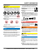
Safety Information general saFetY caution never operate this equipment without proper protective clothing, shatterproof glasses, respiratory protection, hearing protection, steel-toed boots and other protective devices required by the job or city and state regulations. never operate this equipment when not feeling well due to fatigue, illness or when under medication. never operate this equipment under the influence of drugs or alcohol.
Safety Information engine saFetY daNgeR The engine fuel exhaust gases contain poisonous carbon monoxide. This gas is colorless and odorless, and can cause death if inhaled. The engine of this equipment requires an adequate free flow of cooling air. never operate this equipment in any enclosed or narrow area where free flow of the air is restricted. If the air flow is restricted it will cause injury to people and property and serious damage to the equipment or engine.
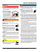
Safety Information Fuel saFetY daNgeR dO NOT start the engine near spilled fuel or combustible fluids. Diesel fuel is extremely flammable and its vapors can cause an explosion if ignited. Make sure the hitch and coupling of the towing vehicle are rated equal to, or greater than the trailer “gross vehicle weight rating.” alWaYs inspect the hitch and coupling for wear. never tow a trailer with defective hitches, couplings, chains, etc.
Safety Information electrical saFetY daNgeR dO NOT touch output terminals during operation. Contact with output terminals during operation can cause electrocution, electrical shock or burn. The electrical voltage required to operate the generator can cause severe injury or even death through physical contact with live circuits. Turn generator and all circuit breakers OFF before performing maintenance on the generator or making contact with output terminals.
Safety Information If the battery liquid (dilute sulfuric acid) comes into contact with clothing or skin, rinse skin or clothing immediately with plenty of water. emissions inFormation If the battery liquid (dilute sulfuric acid) comes into contact with eyes, rinse eyes immediately with plenty of water and contact the nearest doctor or hospital to seek medical attention.
Specifications Model Type Table 1. Generator Specifications DCA300SSCU2/ DCA300SSCU4i Revolving field, self ventilated, open protected type synchronous generator Star with Neutral 3 264 kW (330 kVA) 240 kW (300 kVA) Armature Connection Phase Standby Output Prime Output 3Ø Voltage (L-L/L-N) 208Y/120, 220Y/127, 240Y/139 Voltage Change-Over Bd. at 3Ø 240/139 3Ø Voltage (L-L/L-N) 416Y/240, 440Y/254, 480Y/277 Voltage Change-Over Bd. at 3Ø 480/277 1Ø Voltage (L-L/L-N) 240/120 Voltage Change-Over Bd.
Dimensions C B D MAXIMUM LIFTING POINT 16,500 lbs. (7,484 kg) TOP VIEW E A F 300 SIDE VIEW G Figure 1. Dimensions FRONT VIEW Table 3. Dimensions H Reference Letter Dimension in. (mm) Reference Letter Dimension in. (mm) A 39.76 (1,010) F 43.89. (1,115) B 39.76 (1,010) G 149.60 (3,800) C 43.89. (1,115) H 70.86 (1,800) D 23.03 (585) I 59.05 (1,500) E 25.19 (640) I 60 hz generator• operation manual — rev.
Installation Figure 2. Typical Generator Grounding Application page 14 — dca300sscu2/4i 60 hz generator • operation and Parts manual — rev.
Installation Outdoor Installation Generator Grounding Install the generator in a area that is free of debris, bystanders, and overhead obstructions. Make sure the generator is on secure level ground so that it cannot slide or shift around. Also install the generator in a manner so that the exhaust will not be discharged in the direction of nearby homes. To guard against electrical shock and possible damage to the equipment, it is important to provide a good EARTH ground (Figure 2).
General Information Generator Open Delta Excitation System This generator (Figure 3) is designed as a high quality portable (requires a trailer for transport) power source for telecom sites, lighting facilities, power tools, submersible pumps and other industrial and construction machinery. Each generator is equipped with the state of the art “OpenDelta” excitation system. The open delta system consist of an electrically independent winding wound among stationary windings of the AC output section.
Major Components 3 2 300 1 4 6 5 300 V U W O GND 7 12 11 25 0 50 75 PSI 140 100 180 260 18 12 220 °F 100 OIL PRESS 24 VOLTS 6 WATER TEMP 30 INCREASE DECREASE BATTERY ½ 120 150 180 60 E F FUEL 0 RPMX10 V 210 SPEED U W OFF ECU V-W Series 800 Controller Engine Started Shutdown W-U U-V OFF 8 Pre-Alarm Screen Alarm Acknowledge Change Option Program/ Exit 9 10 Denyo Table 4. Generator Major Components ITEM NO.
engine control unit (ecu) 1 ECU Series 800 Controller Engine Started Shutdown A Pre-Alarm 25 B C D 0 50 75 PSI 140 100 180 260 18 12 220 °F 100 OIL PRESS 24 VOLTS 6 WATER TEMP INCREASE 30 ½ 120 150 180 60 °F E F FUEL DECREASE BATTERY 0 RPMX10 V 210 SPEED U W OFF ECU V-W Series 800 Controller Engine Started W-U U-V Shutdown OFF Pre-Alarm Alarm Screen Acknowledge Change E Option F G Alarm Screen Acknowledge Change Program Exit Option Program Exit H 2
ENGINE/Generator Control Panel 1 25 0 50 75 PSI A 140 100 100 180 °F B 18 12 220 25 0 24 VOLTS 6 260 C 50 75 PSI 140 100 OIL PRESS 180 260 120 150 F INCREASE DECREASE 9 180 60 FUEL WATER TEMP 30 BATTERY ½ °F 8 4 24 VOLTS 6 WATER TEMP 30 18 12 220 °F 100 E OIL PRESS 3 2 0 RPMX10 210 5 15 V SPEED U BATTERY W OFF D 120 150 V-W 180 ECU Series 800 Controller 60 E °F FUEL F 10 6 E ½ 0 U-V Engine Started RPMX10 OFF Shutdown 210
OUTPUT TERMINAL PANEL FAMILIARIZATION Output Terminal Panel Output Terminal Familiarization The Output Terminal Panel (Figure 6) shown below is located on the right-hand side (left from control panel) of the generator. Lift up on the cover to gain access to receptacles and terminal lugs.
OUTPUT TERMINAL PANEL FAMILIARIZATION 120 VAC GFCI Receptacles There are two 120 VAC, 20 amp GFCI (Duplex Nema 5-20R) receptacles provided on the output terminal panel. These receptacles can be accessed in any voltage change-over board configuration. Each receptacle is protected by a 20 amp circuit breaker. These breakers are located directly above the GFCI receptacles. Remember the load output (current) of both GFCI receptacles is dependent on the load requirements of the U, V, and W output terminal lugs.
OUTPUT TERMINAL PANEL FAMILIARIZATION Connecting Loads Over Current Relay Loads can be connected to the generator by the Output Terminal Lugs or the convenience receptacles (Figure 11). Make sure to read the operation manual before attempting to connect a load to the generator. An over current relay (Figure 12) is connected to the main circuit breaker. In the event of an overload, both the circuit breaker and the over current relay may trip.
Load Application Single Phase Load Three Phase Load Always be sure to check the nameplate on the generator and equipment to insure the wattage, amperage, frequency, and voltage requirements are satisfactorily supplied by the generator for operating the equipment. When calculating the power requirements for 3-phase power use the following equation: Generally, the wattage listed on the nameplate of the equipment is its rated output.
GENERATOR OUTPUTS Generator Output Voltages Maximum Amps A wide range of voltages are available to supply voltage for many different applications. Voltages are selected by applying jumpers (6) to the voltage change-over board (Figure 13). To obtain some of the voltages as listed in Table 7 (see below) will require a fine adjustment using the voltage regulator (VR) control knob located on the control panel. Table 8 shows the maximum amps the generator can provide. DO NOT exceed the maximum amps as listed.
GENERATOR OUTPUTS/gauge reading how to Read the ac ammeter and ac voltage gauges The AC ammeter and AC voltmeter gauges are controlled by the AC ammeter and AC voltmeter change-over switches. Both of these switches are located on the control panel and DO NOT effect the generator output. They are provided to help observe how much power is being supplied, produced at the UVWO terminals lugs.
OUTPUT TERMINAL PANEL CONNECTIONS UVWO Terminal Output Voltages Various output voltages can be obtained using the UVWO output terminal lugs. The voltages at the terminals are dependent on the placement of the jumpers plates (6) on the Voltage Change-Over Board and the adjustment of the Voltage Regulator Control Knob.
OUTPUT TERMINAL PANEL CONNECTIONS 3Ø-480V UVWO Terminal Output Voltages 1Ø-480V UVWO Terminal Output Voltages 1. Jumper the voltage change-over board for 480V operation as shown in Figure 24. This configuration uses 6 jumper plates in 3 different positions. Remember there are 2 jumper plates at every position. Every jumper plate must be used. 1. Make sure the voltage change-over board is jumpered for 480V operation as shown in Figure 24. Figure 24. Voltage Change-Over Board 480V Configuration 2.
inspection/SETUP Circuit Breakers To protect the generator from an overload, a 3-pole, 800 amp, main circuit breaker is provided to protect the U,V, and W Output Terminals from overload. In addition two single-pole, 20 amp GFCI circuit breakers are provided to protect the GFCI receptacles from overload. Three 50 amp load circuit breakers have also been provided to protect the auxiliary receptacles from overload. Make sure to switch ALL circuit breakers to the OFF position prior to starting the engine.
inspection/SETUP Refueling Procedure: 4. Remove fuel cap (internal fuel tank ) and fill tank as shown in (Figure 31). WARNING Diesel fuel and its vapors are dangerous to your health and the surrounding environment. Avoid skin contact and/or inhaling fumes. 3. Level Tanks — Make sure fuel cells are level with the ground. Failure to do so will cause fuel to spill from the tank before reaching full capacity (Figure 30).
inspection/SETUP Coolant (Antifreeze/Summer Coolant/ Water) Cummins recommends antifreeze/summer coolant for use in their engines, which can be purchased in concentrate (and mixed with 50% demineralized water) or pre-diluted. See the Cummins Engine Owner’s Manual for further details. Cleaning the Radiator The engine may overheat if the radiator fins become overloaded with dust or debris. Periodically clean the radiator fins with compressed air.
inspection/SETUP Battery When connecting battery do the following: This unit is of negative ground DO NOT connect in reverse. Always maintain battery fluid level between the specified marks. Battery life will be shortened, if the fluid level are not properly maintained. Add only distilled water when replenishment is necessary. 1. NEVER connect the battery cables to the battery terminals when the Auto-Off/Reset-Manual Switch is in either the AUTO or MANUAL position.
GENERATOR START-UP PROCEDURE (MANUAL) Before Starting Starting (Manual) CAUTION The engine’s exhaust contains harmful emissions. ALWAYS have adequate ventilation when operating. Direct exhaust away from nearby personnel. 1. Place the engine speed switch (Figure 38) in the LOW (down) position. Figure 38. Engine Speed Switch (Low) WARNING NEVER manually start the engine with the main, GFCI or auxiliary circuit breakers in the ON (closed) position. 1. Place the main, G.F.C.I., and aux.
GENERATOR START-UP PROCEDURE (MANUAL) 5. The generator’s AC-voltmeter (Figure 42) will display the generator’s output in VOLTS. If the voltage is not within the specified tolerance, 140 180 220 °F 100 260 WATER TEMP Figure 42. Voltmeter 6. Use the voltage adjustment control knob (Figure 43) to increase or decrease the desired voltage. Figure 46. Coolant Temperature Gauge 10. The tachometer gauge (Figure 47) will indicate the speed of the engine when the generator is operating.
GENERATOR START-UP PROCEDURE (AUTO MODE) Starting (Auto Mode) DANGER Before connecting this generator to any building’s electrical system, a licensed electrician must install an isolation (transfer) switch. Serious damage to the building’s electrical system may occur without this transfer switch. CAUTION When connecting the generator to a isolation (transfer) switch, ALWAYS have power applied to the generator’s internal battery charger. This will ensure that the engine will not fail due to a dead battery.
GENERATOR SHUT-DOWN PROCEDURES WARNING NEVER stop the engine suddenly except in an emergency. Normal Shutdown Procedure To shutdown the generator, use the following procedure: 1. Place both the MAIN, GFCI and LOAD circuit breakers as shown in Figure 52 to the OFF position. 6. Remove all loads from the generator. 7. Inspect entire generator for any damage or loosening of components that may have occurred during operation. Emergency Shutdown Procedure 1.
Maintenance 10 Hrs DAILY Table 12. Inspection/Maintenance Engine Check Engine Fluid Levels X Check Air Cleaner X Check Battery Acid Level X Check Fan Belt Condition X Check for Leaks X Check for Loosening of Parts X 250 Hrs Replace Engine Oil and Filter 1 X Clean Air Filter X Check Fuel Filter/Water Separator Bowl 1000 Hrs X Change Fuel Filter X Clean Radiator and Check Coolant Protection Level X 2 X 3 Check all Hoses and Clamps X 4 Clean Inside of Fuel Tank X 2000 HRS.
Maintenance Cleaning Inside the Fuel Tank Drain the fuel inside the fuel tank completely. Using a spray washer (Figure 57) wash out any deposits or debris that have accumulated inside the fuel tank. Figure 56. Air Cleaner/Indicator If the engine is operating in very dusty or dry grass conditions, a clogged air cleaner will result. This can lead to a loss of power, excessive carbon buildup in the combustion chamber and high fuel consumption. Change air cleaner more frequently if these conditions exists.
Maintenance Air Removal If air enters the fuel injection system of a diesel engine, starting becomes impossible. After running out of fuel, or after disassembling the fuel system, bleed the system according to the following procedure. See the Cummins Engine Manual for details. To restart after running out of fuel, turn the switch to the “ON” position for 15-30 seconds. Try again, if needed. This unit is equipped with an automatic air bleeding system.
Maintenance Jacket Water Heater and Internal Battery Charger 120 VAC Input Receptacles (OPTIONAL) This generator can be optionally equipped with two 120 VAC, 20 amp input receptacles located on the output terminal panel. The purpose of these receptacles is to provide power via commercial power to the jacket water heater and internal battery charger. If the generator will be used daily, the battery should normally not require charging.
Maintenance Emission control The emission control system employed with the Cummins QSB&-G6 diesel engine consist of a Diesel Oxidation Catalyst (DOC) and a Diesel Particulate Filter (DPF). The oxidation catalyst and particulate filter are housed in one unit. See Figure 62. These devices help in filtering out large amounts of harmful Nitrogen Oxides (NOx) and Particulate Matter (PM) which are emitted by diesel engines. These exhaust emissions pose serious environmental and health risks.
Maintenance ECU Forced regeneration procedure Follow the steps below to initiate a forced regeneration: Series 800 Controller Engine Started DPF STAT Shutdown Pre-Alarm 1. Verify that the AMBER pre-alarm LED is ON or FLASHING and the DPF symbol is shown on the ECU display. 2. Place all circuit breakers in the OFF position. 3. Place the engine speed switch in the LOW position. Alarm Screen Acknowledge Change Option Program Exit Figure 61.
trailer Maintenance The following trailer maintenance guidelines are intended to assist the operator in preventive maintenance. trailer BraKes 6. Replace the adjusting-hole cover. 7. Repeat the above procedure on all brakes. 8. Lower the trailer to the ground. Properly functioning brake shoes and drums are essential to ensure safety. The brakes should be inspected the first 200 miles of operation. This will allow the brake shoes and drums to seat properly.
trailer Maintenance Warning ADJUSTABLE CHANNEL Failure to maintain proper fluid level in the actuator may result in loss of braking action which could cause severe property damage, injury or death. Periodically check the actuator mounting fasteners for damage or loosening. Inspect the actuator for worn or damaged parts. As you are towing your trailer, be aware of any changes in braking quality. This could be an early warning of brake or actuator malfunction and requires immediate attention.
trailer Maintenance After removing the dust cap, cotter pin, spindle nut and spindle washer, remove the hub to inspect the bearings for wear and damage. Replace bearings that have flat spots on rollers, broken roller cages, rust or pitting. Always replace bearings and cups in sets. The inner and outer bearings are to be replaced at the same time. daNgeR Improper weld repair will lead to early failure of the trailer structure and can cause serious injury or death.
trailer guidelines The following guidelines are intended to assist the operator in the operation and handling of a trailer. Shift your automatic transmission into a lower gear for city driving. Safety precautions should be followed at all times when operating a trailer. Failure to read, understand and follow the safety guidelines could result in injury to yourself and others. Loss of control of the trailer or tow vehicle can result in death or serious injury.
trailer guidelines driving conditions When towing a trailer, you will have decreased acceleration, increased stopping distance, and increased turning radius (which means you must make wider turns to keep from hitting curbs, vehicles, and anything else that is on the inside corner). In addition, you will need a longer distance to pass, due to slower acceleration and increased length. Be alert for slippery conditions.
trailer guidelines inoperaBle BraKes, lights or mirrors Be sure that the brakes and all of the lights on your trailer are functioning properly before towing your trailer. Check the trailer taillights by turning on your tow vehicle headlights. Check the trailer brake lights by having someone step on the tow vehicle brake pedal while you look at trailer lights. Do the same thing to check the turn signal lights. See Trailer Wiring Diagram section in this manual.
trailer guidelines VI N TA G VIN TAG Figure B. VIN Tag Location To determine the “empty” or “net” weight of your trailer, weigh it on an axle scale. To find the weight of the trailer using an axle scale, you must know the axle weights of your tow vehicle without the trailer coupled. Some of the trailer weight will be transferred from the trailer to the tow vehicle axles, and an axle scale weighs all axles, including the tow vehicle axles.
trailer guidelines emergencY Flares and triangle reFlectors Ball hitch coupler It is wise to carry these warning devices even if you are not towing a trailer. It is particularly important to have these when towing a trailer because the hazard flashers of your towing vehicle will not operate for as long a period of time when the battery is running both the trailer lights and tow vehicle lights. A ball hitch coupler (Figure C) connects to a ball that is located on or under the rear bumper of tow vehicle.
trailer guidelines or is worn, the trailer can come loose from the tow vehicle and may cause death or serious injury. the trailer tongue. Wood or concrete blocks may also be used. THE TOW VEHICLE, HITCH AND BALL MUST HAVE A RATED TOWING CAPACITY EQUAL TO OR GREATER THAN THE TRAILER gross vehicle Weight rating (gvWr). IT IS ESSENTIAL THAT THE HITCH BALL BE OF THE SAME SIZE AS THE COUPLER.
trailer guidelines Breakaway Brake system NOTICE Overloading can damage the tongue jack. dO NOT use the tongue jack to raise the tow vehicle more than one inch. If the coupler cannot be secured to the hitch ball, do not tow the trailer. Call your dealer for assistance. Lower the trailer so that its entire tongue weight is held by the hitch and continue retracting the jack to its fully retracted position.
trailer guidelines connecting trailer lights pintle hitch coupler Connect the trailer lights to the tow vehicle’s electrical system using the electric connectors at the front of the trailer (tongue). Refer to the wiring diagram shown in the trailer wiring diagram section of this manual. Before towing the trailer check for the following: A pintle eye coupler (Figure G) connects to a pintle-hook hitch that is located on or under the rear bumper of the tow vehicle.
trailer guidelines the ball andcoupler system. All bent or broken coupler parts must be replaced before towing the trailer. THE TOW VEHICLE, PINTLE HITCH AND PINTLE COUPLER MUST HAVE A RATED TOWING CAPACITY EQUAL TO OR GREATER THAN THE TRAILER gross vehicle Weight rating (gvWr). IT IS ESSENTIAL THAT THE PINTLE HITCH BE OF THE SAME SIZE AS THE PINTLE COUPLER. The coupler size and load rating (capacity) are marked on the coupler. Hitch capacity is marked on the hitch.
trailer guidelines tire saFetY unsafe tires, lug nuts or Wheels Trailer tires and wheels are more likely to fail than car tires and wheels because they carry a heavier load. Therefore, it is essential to inspect the trailer tires before each tow. If a tire has a bald spot, bulge, cuts, is showing any cords, or is cracked, replace the tire before towing. If a tire has uneven tread wear, take the trailer to a dealer service center for diagnosis.
trailer guidelines There is a vehicle placard (Figure I) located in the same location as the certification label described above. This placard provides tire and loading information. In addition, this placard will show a statement regarding maximum cargo capacity. TIRE AND LOADING INFORMATION The weight of cargo should never exceed XXX kg. Or XXX lbs. TIRE FRONT REAR SPARE SIZE COLD TIRE PRESSURE SEE OWNER’S MANUAL FOR ADDITIONAL INFORMATION Figure I.
trailer guidelines Use the information contained in this section to make tire safety a regular part of your vehicle maintenance routine. Recognize that the time you spend is minimal compared with the inconvenience and safety consequences of a flat tire or other tire failure. tire Fundamentals Federal law requires tire manufacturers to place standardized information on the sidewall of all tires (Figure J).
trailer guidelines uniform tire quality grading standards (utqgs) Treadwear Number: This number indicates the tire’s wear rate. The higher the treadwear number is, the longer it should take for the tread to wear down. For example, a tire graded 400 should last twice as long as a tire graded 200. traction letter: This letter indicates a tire’s ability to stop on wet pavement. A higher graded tire should allow you to stop your car on wet roads in a shorter distance than a tire with a lower grade.
trailer guidelines Table B below will help pinpoint the causes and solutions of tire wear problems. table B. Tire Wear Troubleshooting Wear pattern cause solution Center Wear Over inflation. Adjust pressure to particular load per tire manufacturer. Edge Wear Under inflation. Adjust pressure to particular load per tire manufacturer. Side Wear Loss of camber or overloading. Make sure load does not exceed axle rating. Align wheels. Toe Wear Incorrect toe-in. Align wheels.
trailer guidelines table c. Tire Torque Requirements Wheel size First pass Ft-lBs second pass Ft-lBs Third pass Ft-lBs 12" 20-25 35-40 50-65 13" 20-25 35-40 50-65 14" 20-25 50-60 90-120 15" 20-25 50-60 90-120 16" 20-25 50-60 90-120 Replace any broken or burned-out lamps as necessary. Check the wire harness for cuts, fraying or other damage. If it needs replacing, contact your dealer. Warning Improper operating taillights, stoplights and turn signals can cause collisions.
Generator Wiring Diagram CONTROL BOX COT. B CONTROL PANEL COT. B X U2 U1 V2 V1 X U2 Y U1 Y V2 V1 Z Z W2 W2 W1 O Voltage Change-Over Board-240V Set 1 2 CN1 3 3 4 k P1 P2 1 2 CN3 3 CONTROL BOX SIDE 2 1 SYMBOL W1 V1 U1 1 U2 3 W2 3 2 1 T1 S1 R1 3 1 2 U V W 1 2 CN4 Figure 63.
Engine Wiring Diagram COLOR CODE WIRE COLOR WIRE COLOR B L BR G GR V P BLACK BLUE BROWN GREEN GRAY VIOLET PINK R W Y LB LG O RED WHITE YELLOW LIGHT BLUE LIGHT GREEN ORANGE Figure 64.
Troubleshooting (Generator) Practically all breakdowns can be prevented by proper handling and maintenance inspections, but in the event of a breakdown, use Table 13 shown below for diagnosis of the Generator. If the problem cannot be remedied, consult our company’s business office or service plant. Symptom No Voltage Output Low Voltage Output High Voltage Output Circuit Breaker Tripped Table 13.
Troubleshooting Diagnostics The engine controller of this generator diagnoses problems that arise from the engine control system and the engine itself. 1. With the engine stopped (OFF). Push and hold the Hour Check Button (Figure 65) located on the control panel. HOUR CHECK BUTTON 5. Push the Program/Exit Button on the ECU controller and select the Fault Diagnostics mode.
Explanation of Code in Remarks Column The following section explains the different symbols and remarks used in the Parts section of this manual. Use the help numbers found on the back page of the manual if there are any questions. NOTICE The contents and part numbers listed in the parts section are subject to change without notice. Multiquip does not guarantee the availability of the parts listed. sample parts list no. 1 2% 2% 3 4 part no. part name qtY. remarKs 12345 BOLT .....................1 .....
Suggested Spare Parts dca300ssCU2/DCA300SSCU4 i WHISPERWATT GENERATOR with cummings qsl9-g8 DIESEL ENGINE 1 to 3 units Qty. P/N Description 4............0602015160...........HOSE, RADIATOR, HUMP 4............Y0602015128........HOSE, RADIATOR 3............Y0602015247........BELT, fan 1............4921744.................SENSOR, oil pressure 1............Y0602211320........SWITCH, COOLANT LEVEL 6............0602042588...........FUEL FILTER cartridge 6............0602041224...........FILTER, OIL CARTRIDGE 6...
GENERATOR ASSY. 5A 5 6-6 1-4B 1-4A 6-6A 17A 17 22 22A 9B 9A 9 24 24A 22B 20A 20 13B 13A 13 page 66 — dca300sscu2/4i 60 hz generator • operation and Parts manual — rev.
GENERATOR ASSY. NO. PART NO.
GENERATOR ASSY. (continued) 5A 5 6-6 1-4B 1-4A 6-6A 17A 17 22 22A 9B 9A 9 24 24A 22B 20A 20 13B 13A 13 page 68 — dca300sscu2/4i 60 hz generator • operation and Parts manual — rev.
GENERATOR ASSY. (continued) NO. 14 15 16 17 17A 18 19 20 20A 21 22 22A 22B 23 24 24A PART NO. C3154400003 011106015 M5163600303 0343205150 0043605000 M5163700004 0070506208 0012112040 0042512000 C3132300014 0010006030 952404470 020106050 0605000012 0030020000 030220510 PART NAME SUCTION COVER HEX. HEAD BOLT COUPLING ADAPTER HEX. HEAD BOLT WASHER, LOCK SPACER, BEARING BEARING HEX. HEAD BOLT WASHER, LOCK COVER, FAN HEX. HEAD BOLT WASHER, FLAT NUT RUBBER SUSPENSION HEX. NUT WASHER, LOCK QTY.
CONTROL BOX ASSY. 70 71 24B 24A 24C 25 21 21A 66A 66B 63A 11 65A 65B 66 63 67A 49 31A 69 69A 49A 45A 31B 65 31 55A 55 page 70 — dca300sscu2/4i 60 hz generator • operation and Parts manual — rev.
CONTROL BOX ASSY. NO. 1 2 3 4 4-1 5 6 7 8 9 10 11 12 13 14 15 16 17 18 19 20 21 21A 22 23 24 24A 24B 24C 25 26 27 28 29 30 31 31A 31B 32 33 34 35 36 37 38 39 PART NO.
CONTROL BOX ASSY. (continued) 70 71 24B 24A 24C 25 21 21A 66A 66B 63A 11 65A 65B 66 63 67A 49 31A 69 69A 49A 45A 31B 65 31 55A 55 page 72 — dca300sscu2/4i 60 hz generator • operation and Parts manual — rev.
CONTROL BOX ASSY. (continued) NO. 40 41 42 43 44 45 45A 46 46-1 47 48 49 49A 50 51 52 53 54 55 55A 56 57 58 59 60 61 62 63 63A 64 65 65A 65B 66 66A 66B 67 67A 68 69 69A 70 71 PART NO.
engine AND Radiator ASSY. 32A 29A 22 22A 31A 1A 27 26 26 27 26 27 27 26 3 3C 3B 3A 1-1A 27 26 4 4B 4A page 74 — dca300sscu2/4i 60 hz generator • operation and Parts manual — rev.
engine AND Radiator ASSY. NO. 1 1A 1-1 1-1A 1-2 1-3 1-4 2 3 3A 3B 3C 4 4A 4B 5 6 7 8 9 10 11 12 13 14 15 16 17 18 19 20 21 22 22A 23 24 25 PART NO.
engine AND Radiator ASSY. (continued) 32A 29A 22 22A 31A 1A 27 26 26 27 26 27 27 26 3 3C 3B 3A 1-1A 27 26 4 4B 4A page 76 — dca300sscu2/4i 60 hz generator • operation and Parts manual — rev.
engine AND Radiator ASSY. (continued) NO. 26 27 28 29 29A 30 31 31A 32 32A 33 34 35 36 37 38 39 40 41 42 43 44 PART NO.
engine operating panel ASSY. 2 2 2 4C 4A 6 4 4B 6A 7 page 78 — dca300sscu2/4i 60 hz generator • operation and Parts manual — rev.
engine operating panel ASSY. NO. 1 2 3 4 4A 4B 4C 5 6 6A 7 PART NO. M5351100204 0016906016 1823200010 0021008080 020108060 0040008000 0401450080 M5483000203 0016910030 021112140 0016910030 PART NAME OPERATING PANEL HEX. HEAD BOLT BATTERY SWITCH MACHINE SCREW HEX. NUT SPRING WASHER WASHER, FLAT SET FRAME HEX. HEAD BOLT HEX. NUT HEX. HEAD BOLT QTY. 1 6 1 2 2 2 2 1 2 2 3 REMARKS DCA300ssCU2/4i 60 hz generator• operation manual — rev.
output terminal ASSY. 5 6 4 13 15A 15 15A 15 ADD THE FOLLOWING DIGITS AFTER THE PART NUMBER WHEN ORDERING ANY PAINTED PANEL TO INDICATE COLOR OF UNIT: 1-ORANGE 6-CATERPILLAR YELLOW 2-WHITE 7-CATO GOLD 3-SPECTRUM GREY 8-RED 4-SUNBELT GREEN 9-DESERT TAN 5-BLACK THE SERIAL NUMBER MAY BE REQUIRED. page 80 — dca300sscu2/4i 60 hz generator • operation and Parts manual — rev.
output terminal ASSY. NO. 1 2 3 4 5 6 7 8 9 10 11 11-1 12 13 14 15 15A 16 17 18 19 20 21 22 23 24 25 26 27 28 29 30 31 32 33 34 35 36 37 PART NO.
battery ASSY. 10 12 page 82 — dca300sscu2/4i 60 hz generator • operation and Parts manual — rev.
battery ASSY. NO. 1 2 3 4 5 6 7 8 9 10 11 12 13 PART NO. 0602220196 M9310500404 M9104000004 0602220921 M5346900604 M5346900704 M4346400314 M5346900804 M5346200304 0017116030 0040516000 0017112025 0040512000 PART NAME BATTERY BATTERY SHEET BATTERY BAND BATTERY BOLT SET BATTERY CABLE BATTERY CABLE BATTERY CABLE BATTERY CABLE EARTH CABLE HEX. HEAD BOLT TOOTHED WASHER HEX. HEAD BOLT TOOTHED WASHER QTY. 2 2 1 2 1 1 1 1 1 1 1 1 1 REMARKS DCA300ssCU2/4i 60 hz generator• operation manual — rev.
muffler ASSY. 8A 9A page 84 — dca300sscu2/4i 60 hz generator • operation and Parts manual — rev.
muffler ASSY. NO. 1 2 3 4 5 6 7 8 8A 9 9A 10 11 12 13 14 15 16 17 18 19 PART NO. Y0602300241 M5330400003 0016910025 M5330400104 011008020 0207308000 M5333000203 Y0602325039 Y0602320129 Y0602325038 Y0602320128 M5330300204 M5330300304 011008020 0602326062 M4333100004 M5357300204 011206020 0601851736 Y0602311140 0605515225 PART NAME DEVICE, AFTER TREATMENT BRACKET HEX. HEAD BOLT BAND HEX.
fuel tank ASSY. page 86 — dca300sscu2/4i 60 hz generator • operation and Parts manual — rev.
fuel tank ASSY. NO. 1 1-1 2 3 4 5 6 7 8 9 10 11 12 13 14 15 16 17 18 19 PART NO. M5360100203 0605505070 0605501069 0605516090 7538070 M5364200004 M9310500104 011008020 0207308000 0605515198 1502025103C 0802011104 0150000018 011206020 Y0191500270 0605515198 Y0602042682 Y0602042683 0191503400 0191503700 PART NAME FUEL TANK CAP, FUEL TANK FUEL SENSOR UNIT GASKET MACHINE SCREW TANK BAND SUPPORTER SHEET HEX. HEAD BOLT SUPER LOCK NUT HOSE BAND DRAIN JOINT DRAIN BOLT O-RING HEX.
ENCLOSURE ASSY. 33 60A 31 31A 63A 33A 58A 42A 44 38 62A 56B 41A 56A 52A 56 62A 75 49A 8A 22A 24A 5A 7A 25A 25 5 13A 16 16B 16C 17A 17C 16A 64A 16A 64 17 68A 70A 63A 17B 68 61 61A 69A 59A 57A page 88 — dca300sscu2/4i 60 hz generator • operation and Parts manual — rev.
ENCLOSURE ASSY. NO. 1 2 3 4 5 5A 6 7 7A 8 8A 9 10 11 12 13 13A 14 15 16 16A 16B 16C 17 17A 17B 17C 18 19 20 21 22 22A 23 24 24A 25 25A PART NO.
ENCLOSURE ASSY. (cont.) 33 60A 31 31A 63A 33A 58A 42A 44 38 62A 56B 41A 56A 52A 56 62A 75 49A 8A 22A 24A 5A 7A 25A 25 5 13A 16 16B 16C 17A 17C 16A 64A 16A 64 17 68A 70A 63A 17B 68 61 61A 69A 59A 57A page 90 — dca300sscu2/4i 60 hz generator • operation and Parts manual — rev.
ENCLOSURE ASSY. (cont.) NO. 26 27 28 29 30 31 31A 32 33 33A 34 35 36 37 38 39 40 41 41A 42 42A 43 44 45 46 47 48 49 49A 50 51 52 52A 53 54 55 PART NO.
ENCLOSURE ASSY. (cont.) 33 60A 31 31A 63A 33A 58A 42A 44 38 62A 56B 41A 56A 52A 56 62A 75 49A 8A 22A 24A 5A 7A 25A 25 5 13A 16 16B 16C 17A 17C 16A 64A 16A 64 17 68A 70A 63A 17B 68 61 61A 69A 59A 57A page 92 — dca300sscu2/4i 60 hz generator • operation and Parts manual — rev.
ENCLOSURE ASSY. (cont.) NO. 56 56A 56B 57 57A 58 58A 59 59A 60 60A 61 61A 62 62A 63 63A 64 64A 65 66 67 68 68A 69 69A 70 70A 71 72 73 74 75 76 77 78 PART NO.
rubber seals ASSY. page 94 — dca300sscu2/4i 60 hz generator • operation and Parts manual — rev.
rubber seals ASSY. NO. 1 2 3 4 5 6 7 8 9 10 11 12 13 14 15 PART NO. Y0229201500 0229201400 0228901310 0228900710 0228901015 0228901120 0228901250 0228900650 Y0229400705 0228801210 0229200470 0229201130 0228100560 0228100370 0222100300 PART NAME SEAL RUBBER SEAL RUBBER SEAL RUBBER SEAL RUBBER SEAL RUBBER SEAL RUBBER SEAL RUBBER SEAL RUBBER SEAL RUBBER SEAL RUBBER SEAL RUBBER SEAL RUBBER SEAL RUBBER SEAL RUBBER RUBBER SHEET QTY.
nameplate and decals ASSY. 8-2A page 96 — dca300sscu2/4i 60 hz generator • operation and Parts manual — rev.
nameplate and decals ASSY. NO. 1-1 1-2 1-3 1-4 PART NO. M4550000603 M4550000713 M9520100304 M9520100603 PART NAME QTY. REMARKS DECAL: OPERATING PROCEDURES...............1................M45000060 DECAL: DPF REGEN. PROCEDURES..............1................M45000071 DECAL: SAFETY INSTRUCTIONS....................1................M92010030 DECAL: CAUTION..............................................2................
nameplate and decals ASSY. (cont.) 8-2A page 98 — dca300sscu2/4i 60 hz generator • operation and Parts manual — rev.
nameplate and decals ASSY. (cont.) NO. PART NO. 8-1 M9510200002 8-2 0600500090 8-2A 0021106016 8-3 M5560101004 8-4 M5560101604 8-5 M5560101704 8-6 M5560101804 8-7 M5560101903 8-8 M5560102003 8-9 M5560102103 8-10 M5550000004 8-11 M9512000004 8-12 M9510000104 PART NAME QTY. REMARKS ENCLOSURE GROUP DECAL: MQ........................................................1................M91020000 EMBLEM 2 MACHINE SCREW 4 STRIPE...............................................................2................
Terms and Conditions of Sale — Parts PAYMENT TERMS 5. Parts must be in new and resalable condition, in the original Multiquip package (if any), and with Multiquip part numbers clearly marked. 6. The following items are not returnable: Multiquip reserves the right to quote and sell direct to Government agencies, and to Original Equipment Manufacturer accounts who use our products as integral parts of their own products. a. SPECIAL EXPEDITING SERVICE Terms of payment for parts are net 30 days.
notes DCA300ssCU2/4i 60 hz generator• operation manual — rev.
Operation Manual HERE’S HOW TO GET HELP PLEASE HAVE THE MODEL AND SERIAL NUMBER ON-HAND WHEN CALLING United StateS Multiquip Corporate Office 18910 Wilmington Ave. Carson, CA 90746 Contact: mq@multiquip.com MQ Parts Department Tel.