Operation and Parts Manual SERIES MODEL MTr40sf Tamping Rammer (ROBIN EH092F GASOLINE ENGINE) Revision #0 (11/28/12) To find the latest revision of this publication, visit our website at: www.multiquip.com THIS MANUAL MUST ACCOMPANY THE EQUIPMENT AT ALL TIMES.
proposition 65 warning page 2 — MTX40sf RAMMER • operation and parts manual — rev.
notes MTX40sf RAMMER • operation and parts manual — rev.
Table of Contents MTR40SF Rammer Proposition 65 Warning............................................ 2 Table Of Contents..................................................... 4 Parts Ordering Procedures....................................... 5 Safety Information................................................. 6-9 Specifications......................................................... 10 General Information................................................ 11 Components........................................
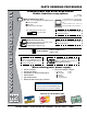
www.multiquip.com Parts Ordering Procedures Ordering parts has never been easier! Choose from three easy options: order via internet (dealers only): best deal! Effective: January 1st, 2006 If you have an MQ Account, to obtain a Username and Password, E-mail us at: parts@multiquip. com. Order parts on-line using Multiquip’s SmartEquip website! ■ View Parts Diagrams ■ Order Parts ■ Print Specification Information To obtain an MQ Account, contact your District Sales Manager for more information.
Safety Information Do not operate or service the equipment before reading the entire manual. Safety precautions should be followed at all times when operating this equipment. Failure to read and understand the safety messages and operating instructions could result in injury to yourself and others. Potential hazards associated with the operation of this equipment will be referenced with hazard symbols which may appear throughout this manual in conjunction with safety messages.
Safety Information geneRal safeTy CauTion neveR operate this equipment without proper protective clothing, shatterproof glasses, respiratory protection, hearing protection, steel-toed boots and other protective devices required by the job or city and state regulations. alWays know the location of the nearest phone or keep a phone on the job site. Also, know the phone numbers of the nearest ambulance, doctor and fire department. This information will be invaluable in the case of an emergency.
Safety Information engine safeTy dangeR The engine fuel exhaust gases contain poisonous carbon monoxide. This gas is colorless and odorless, and can cause death if inhaled. fuel safeTy dangeR DO NOT add fuel to equipment if it is placed inside truck bed with plastic liner. Possibility exists of explosion or fire due to static electricity. The engine of this equipment requires an adequate free flow of cooling air.
Safety Information TRanspoRTing safeTy CauTion NEVER allow any person or animal to stand underneath the equipment while lifting. NOTICE Before lifting, make sure that the equipment parts (hook and vibration insulator) are not damaged and screws are not loose or missing. Always make sure crane or lifting device has been properly secured to the lifting bail (hook) of the equipment. alWays shutdown engine before transporting. neveR lift the equipment while the engine is running.
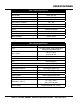
specifications Overall Height Overall Width Over Length Shoe Size (W x L) No. of Impacts Per Minute Tamping Area Impact Force Clutch Travel Speed Stroke (Jump Height) Operating Weight Model Type Bore x Stroke Table 1. Rammer Specifications 43.7 in. (1,110 mm)) 13.8 in. (351 mm) 24.5 in. (622 mm) 5.9 x 10.6 in. (150 x 270 mm) 650 ~ 699 1,453 sq. ft. per hr (135 sq.m per hr) 1,215 lbs./blow ( 550 kg/blow) Automatic Centrifugal 30 fpm (9 mpm)) 2.2 in. (55 mm) 101 lbs. (46 kg) Table 2.
general Information The Multiquip MTR40SF tamping rammer is a powerful compacting tool capable of applying a tremendous force in consecutive impacts to a soil surface. Its applications include soil compacting for r backfilling for gas pipelines, water pipelines and cable installation work. The impact force of the MTR40SF levels and uniformly compacts voids between soil particles to increase dry density. Circular motion is converted to create impact force.
components 8 7 1 3 2 9 6 11 5 11 10 4 Figure 1. MTR40SF Rammer Figure 1 shows the location of the controls and components for the MTR40SF Tamping Rammer. The functions of each control is described below: 1. Throttle Lever — Used to adjust engine speed (rpm). Move lever forward (SLOW) to reduce engine speed, move lever back toward operator (FAST) to increase speed. 2. Fuel Shut-Off Valve — Supplies fuel from the fuel tank to the engine. To begin fuel flow, move the fuel shut-off valve downward. 3.
basic engine Figure 2. Robin Engine The engine (Figure 2) must be checked for proper lubrication and filled with fuel prior to operation. Refer to the manufacturer's engine manual for instructions and details of operation and servicing. 1. Secondary Air Cleaner — Prevents dirt and other debris from entering the fuel system. Remove wingnut on top of air filter cannister to gain access to filter element. 2. Choke Lever — Used when starting the engine. Normally used in cold weather conditions.
inspection This section is intended to assist the operator with the Fuel INSPECTION inspection of the rammer. It is extremely important that 1. This rammer is equipped with a two-cycled gasoline this section be read carefully before attempting to operate This section is intended to assist the operator with the inspection Fuel engine. Use only unleaded gasoline. High test ethyl theoframmer. the MTR40SF Tamping Rammer. It is extremely important that 1. This INSPECTION gasoline isisnot recommended.
inspection 4. If the oil level is low (Figure 6), fill to the edge of the oil fillerhole with the recommended oil type (Table 3). Maximum oil capacity is .079 gallons (0.3 liters). Figure 6. Oil Level . Table 3. Motor Oil Grade Season or Temperature Grade of motor oil (higher than MS class) Spring, Summer or Autumn +120° F to +15° F SAE 30 Winter +40° F to +15° F SAE 30 Below +15° F SAE 10W-30 general Inspection 1. Check all nuts, bolts fasteners for tightness. Retighten as necessary. 2.
OPERATION operation OPERATION cold weather, thewith unit withlever choke lever "Fully 4.4. InIncold weather, startstart the unit choke "Fully Closed" Operation CAUTION 4. In cold weather, start the unit with choke lever "Fully Closed" Operation Closed" 10). In warm weather or when the (Figure 10).Figure In warm weather or when the engine is warm, The following steps outline the procedure for starting the engine: (Figure 10).
operation OPERATION 1. To start the rammer tamping action, move the throttle Operation lever (Figure 12) quickly from IDLE (close) to the FULL OPEN DOtamping NOT move themove throttle slowly 1. To startposition. the rammer action, thelever throttle lever as this may cause damage the clutch spring. from IDLEto(close) to theorFULL OPEN (Figure 12) quickly position. DO NOT move the throttle lever slowly as this may cause damage to the clutch or spring. 3.
maintenance Daily Thoroughly remove dirt and oil from the engine compartment and rammer. Clean or replace the air cleaner elements as necessary. Check and retighten all fasteners as necessary. Check the bellows for oil leaks. Repair or replace as needed. 200 - 300 HOURS (Pre-Cleaner) Remove the element from the pre-cleaner (Figure 16) at the top of the crankcase (body side) and clean it with cleaning oil (kerosene). Figure 17.
maintenance Crankcase Lubrication Spark Plug The rammer crankcase bearings (Figure 19) should be lubricated with five shots of grease with a hand grease gun after each eight (8) hours of use. Remove and clean the spark plug (Figure 20), then adjust the spark gap to 0.024 ~0.028 inch (0.6~0.7 mm). This unit has electronic ignition, which requires no adjustments. Figure 20. Spark PLug Gap Long Term Storage Figure 19.
maintenance Table 4. Engine Maintenance Schedule DESCRIPTION (3) Engine Oil Air Cleaner All Nuts & Bolts OPERATION CHECK CHANGE CHECK FIRST MONTH BEFORE OR 10 HRS. Cooling Fins Spark Arrester Fuel Tank Fuel Filter Idle Speed Valve Clearance Fuel lines EVERY EVERY YEAR 2 YEARS OR OR 100 HRS. 200 HRS.. X X X (1) X CHECK-CLEAN Spark Plug EVERY 6 MONTHS OR 50 HRS. X CHANGE Re-tighten If Necessary EVERY 3 MONTHS OR 25 HRS.
troubleshooting Troubleshooting (engine) symptom possible problem Combo lever in incorrect position? Make sure combo lever is in start position. Spark plug bridging? Check gap, insulation or replace spark plug. Carbon deposit on spark plug? Clean or replace spark plug. Short circuit due to deficient spark plug insulation? Check spark plug insulation, replace if worn. Improper spark plug gap? Set to proper gap. Fuel reaching carburetor? Check fuel line.
troubleshooting Troubleshooting (engine) - continued symptom Weak in power, compression is proper and does not misfire. Weak in power, compression is proper but misfires. Engine overheats. Rotational speed fluctuates. Recoil starter malfunctions. (if applicable) Starter malfunctions. possible problem Air cleaner dirty? Clean or replace air cleaner. Improper level in carburetor? Check float adjustment, rebuild carburetor. Defective spark plug? Clean or replace spark plug.
troubleshooting symptom Engine runs but rammer jumps erratically or not at all. Troubleshooting (Rammer) possible problem Operating speed of throttle lever is incorrectly set? Oil in excess? Clutch slips? Spring Failure? Speed of engine improper? Soil over-compacted? solution Set throttle lever to correct position. Drain excess oil. Bring to correct level. Replace or adjust clutch. Replace spiral spring. Adjust engine speed to correct operating RPM setting. Shut down machine and test soil.
Explanation of Code in Remarks Column The following section explains the different symbols and remarks used in the Parts section of this manual. Use the help numbers found on the back page of the manual if there are any questions. NOTICE The contents and part numbers listed in the parts section are subject to change without notice. Multiquip does not guarantee the availability of the parts listed. saMple paRTs lisT no. 1 2% 2% 3 4 paRT no. paRT naMe QTy. ReMaRks 12345 BOLT .....................1 .....
Suggested Spare Parts MTR40SF TAMPING RAMMER with ROBIN robin EH09-2F engine 1 to 3 units Qty. P/N Description 1............956100040.............THROTTLE WIRE 3............362030030.............ELEMENT, AIR CLEANER 1............361910070.............CAP, FUEL TANK W/STRAP 3............301419750.............FILTER, IN-LINE FUEL 3............0650140380...........SPARK PLUG 1............2745011208...........ROPE, RECOIL STARTER 3............20F3260608..........
nameplates and decals NAMEPLATE AND DECALS 1 16 2 *$62/,1( 21/< NPA 1017 J %HIRUH 2SHUDWLRQ To start, switch must be in the “21 ” position Check all nuts and bolts for tightness Keep machine at the upright operating position to check NPA 293 J 1. Give each grease fitting five (5) shots of grease with a hand grease gun. 2. Check the engine oil level and if the level is low, it should be refilled from the filler hole.
nameplates and decals NO. PART NO. 1 920210170 2 920211000 3 920203990 4 920209570 5 920208960 6 920210160 7 920203290 8 920209630 9 10 920100120 11 920210180 12 920209100 13 920209610 14 920208310 15 920100240 16 920202930 17 920206910 18 920207690 19 920211690 20 920214100 PART NAME QTY.
CRANKCASE AND ENGINE ASSY. crankcase and engine assy page 28 28 — MTX40sf RAMMER • operation andAND parts manual — rev. #0 (11/28/12) PAGE — MTR40SF RAMMER — OPERATION PARTS MANUAL — REV.
crankcase and engine assy NO. 1 2 3 4 5 6 7 9 10 11 13 14 15 16 17 18 20 21 22 23 24 25 26 27 27-1* 27-3* 27-4* 27-5* 28 29* 30 32 33 34 35 37 38 39 40 PART NO.
CRANKCASE AND ENGINE ASSY. crankcase and engine assy page 30 28 — MTX40sf RAMMER • operation andAND parts manual — rev. #0 (11/28/12) PAGE — MTR40SF RAMMER — OPERATION PARTS MANUAL — REV.
crankcase and engine assy NO. 41 42 63 64 65 66 67 68 69 71 71-1# 71-2# 71-3# 71-4# 72 73 74 75 81 86 PART NO. 0031008000 0310060020 959006120 362341620 362341630 3013820 2741600113 0011408250 0011408300 362116871 362030011 362030020 362030030 362030040 362341210 507010110 050300070 0401450080 306010020 911210918 PART NAME QTY. REMARKS WASHER............................................................4................
GUIDE CYLINDER AND FOOT ASSY. guide cylinder assy page 32 — MTX40sf RAMMER • operation and parts manual — rev. #0 (11/28/12) PAGE 32 — MTR40SF RAMMER — OPERATION AND PARTS MANUAL — REV.
guide cylinder assy NO. 1 2 3 4 6 7 8 9 11 12 13 14 15 16 18 19 20 21 22 23 25 26 PART NO. 305464130 368459920 305337980 305451550 305446400 305446410 305446420 305212710 305112730 065105010 080510680 351010050 305446430 001220816 305446440 001520815 305446450 305446460 011208035 020308060 050100800 012210025 PART NAME QTY.
TANK AND HANDLE ASSY. fuel tank and handle assy page 34 — MTX40sf RAMMER • operation and parts manual — rev. #0 (11/28/12) PAGE 34 — MTR40SF RAMMER — OPERATION AND PARTS MANUAL — REV.
fuel tank and handle assy NO. 1 2 3A 3B 4 5 6 7 9# 10 11# 17# 18# 19 20# 21 22 23 24 31# 32 33 34 41# 43 44* 45* 47* 48* 49* 50* 51* 52* 53* 54 55 56* 57* 58* 59 60 61 PART NO.
FOOT ASSY. foot(OPTION) assy page 36 — MTX40sf RAMMER • operation and parts manual — rev.
foot assy NO. 30 31* 32* 33* 34* 35* 36* 37* 38* 39* PART NO. 305910050 306347930 306347960 306461630 009110033 021110120 030210250 009110034 021112140 030212300 PART NAME QTY. REMARKS FOOT ASSY. 150B..............................................1................INCLUDES ITEMS W/ * FOOT 150B 1 METAL SHEET 150B 1 FOOT COVER 1 SUNK HEAD BOLT 10X50 H 2 NYLON NUT M10...............................................2................REPLACES 022711012 WASHER, LOCK M10 2 SUNK HEAD BOLT 12X65 H 4 NYLON NUT M12.....
NARROW FOOT ASSY. (OPTION) NARROW FOOT ASSY. (OPTION) page 38 — MTX40sf RAMMER • operation and parts manual — rev. #0 (11/28/12) PAGE 38 — MTR40SF RAMMER — OPERATION AND PARTS MANUAL — REV.
NARROW FOOT ASSY. (OPTION) NO. A A 1* 1# 2* 2# 3* 3# 4*# 5*# 6*# 7*# 8*# 9*# PART NO. 305910060 305910070 306347940 306347920 306347970 306347950 306461630 306461620 015110050 021110120 030210250 015112060 021112140 030212300 PART NAME QTY. REMARKS FOOT ASSY. 200B..............................................1................INCLUDES ITEMS W/ * FOOT ASSY. 100B..............................................1................INCLUDES ITEMS W/ # FOOT 200B........................................................
TRENCH SHOEassy ASSY. trench shoe PAGE MTR40SF RAMMER — OPERATION AND PARTS MANUAL — REV. #5 (11/01/11) page 4040 —— MTX40sf RAMMER • operation and parts manual — rev.
trench shoe assy NO. 11 11 11 12 13 14 PART NO. 305333160 305333170 305334390 012212035 020312100 0039312000 PART NAME QTY. REMARKS TRENCH SHOE 500H-120B 1 TRENCH SHOE 800H-120B 1 TRENCH SHOE 305H-100B 1 BOLT 12X35 T....................................................4................REPLACES 001221235 NUT M12 4 WASHER, LOCK M12........................................4................REPLACES 030212300 MTX40sf RAMMER • operation and parts manual — rev.
ROBIN —CRANKCASE CRANKCASEassy. ASSY. ROBINEH09-2F EH09-2F ENGINE engine — page4242——MTR40SF MTX40sfRAMMER RAMMER—• operation PAGE OPERATION and AND parts PARTS manual MANUAL — — rev. REV.
ROBIN EH09-2F engine — CRANKCASE assy. NO. 10 20& 26& 30# 40# 50# 70 75# 80 90 150 160 161 205 210 220* 230* 250 260 265* 268* 270 280% 300 430 437 438 439 610 620 630 631 680 685 690 700 710 721 722 723 724 725 726 810 830 860 960 PART NO.
ROBIN EH09-2F —— CRANKSHAFT AND PISTON ASSY. robin EH09-2FENGINE engine CRANKSHAFT, piston assy. PISTON RING SET (STD) 370 (O/S 0.25) 371 (O/S 0.50) 372 PISTON KIT 390 (STD) (O/S 0.25) 391 (O/S 0.50) 392 PISTON (STD) 360 (O/S 0.25) 361 (O/S 0.50) 362 350 380 380 310 320 60 40 41 42 50 70 105 10 80 PAGE 44 — MTR40SF RAMMER — OPERATION AND PARTS MANUAL — REV. #5 (11/01/11) page 44 — MTX40sf RAMMER • operation and parts manual — rev.
robin EH09-2F engine — CRANKSHAFT, piston assy. NO. 10 40 41 42 50 60 70 80 105 310 320% 350 360 361 362 370 371 372 380 390 391 392 PART NO. 2842030101 0230200100 0230200110 0230200120 0021814000 0032014000 0053203101 0053204201 0173120010 2842250130 2842300103 2302330103 28423401H3 28423402H3 28423403H3 2842351107 2842351207 2842351307 0565110010 28427011H7 28427012H7 28427013H7 PART NAME QTY. REMARKS CRANKSHAFT CP 1 SPACER T=0.8 1 SPACER T=1.0 1 SPACER T=1.2 1 NUT 1 SPRING WASHER.......................
ROBIN EH09-2F ENGINE — INTAKE AND EXHAUST ASSY. robin EH09-2F engine — intake, exhaust assy. page 46 — MTX40sf RAMMER • operation and parts manual — rev. #0 (11/28/12) PAGE 46 — MTR40F RAMMER — OPERATION AND PARTS MANUAL — REV.
robin EH09-2F engine — intake, exhaust assy. NO. 10 34% 35% 36% 37% 38% 50 60 70 80 90 95 210 220 230 240 260 310 340 351 357 365 366 370 540 550 560 PART NO. 2843170121 2273860123 2843640103 0051904100 0031517000 2743870123 2743330103 2743360103 2743370203 2743340103 2743350103 13210KA031 2743530103 2843600113 2693580103 0170060090 2743650103 20F3010501 2843520103 0023808000 0200080170 0110060460 0011408160 0130080240 1063292103 2843590213 1573500103 PART NAME QTY. REMARKS CAMSHAFT CP....................
ROBIN EH09-2F ENGINE — CARBURETOR ASSY. robin EH09-2F engine — CARBURETOR assy. PAGE OPERATION and AND parts PARTS manual MANUAL — page48 48——MTR40SF MTX40sfRAMMER RAMMER—• operation — REV. rev.
robin EH09-2F engine — CARBURETOR assy. NO. 210 2# 3# 4# 5# 6# 9# 10# 11# 12# 13# 14# 17# 18# 19# 20# 21# 22# 25# 26# 27# 29# 30# 31# 33# 34# 35# 36# PART NO. 2846237200 2306253608 2776258008 2366252808 2796235608 2306244608 2466243508 2796242108 1066238408 2936235008 2796235108 2936253008 2366254008 2366250508 2936250508 2366245008 2376245008 2936252008 1616235208 2366244508 2146251508 2766240008 2106231808 2246245008 2846236008 2936244018 2356242508 2844550103 PART NAME QTY. REMARKS CARBURETOR ASSY.....
ROBIN EH09-2F ENGINE — AIR CLEANER ASSY. robin EH09-2F engine — AIR CLEANER assy. C 500 900 520(40mm) 510 570 PAGE 50 — MTR40SF RAMMER — OPERATION AND PARTS MANUAL —REV. #5 (11/01/11) page 50 — MTX40sf RAMMER • operation and parts manual — rev.
robin EH09-2F engine — AIR CLEANER assy. NO. C 500# 510# 520# 570 850 900# PART NO. 20F3260300 20F3265108 20F3264108 20F3260608 0176060030 2841610403 0732004430 PART NAME QTY. REMARKS AIR CLEANER ASSY. ........................................1................INCLUDES ITEMS W/# PACKING, CLEANER/09-2F 1 CLEANER COVER/EH09-2F/MT 1 ELEMENT ASSY/09-2F/MT 1 SELF LOCK NUT 2 RUBBER PIPE 1 LABEL, CHOKE 1 MTX40sf RAMMER • operation and parts manual — rev.
ROBIN EH09-2F ENGINE —— GOVERNOR, OPERATION ASSY. robin EH09-2F engine governor, operation assy. PAGE 52 — MTR40SF RAMMER — OPERATION AND PARTS MANUAL — REV. #5 (11/01/11) page 52 — MTX40sf RAMMER • operation and parts manual — rev.
robin EH09-2F engine — governor, operation assy. NO. 10 20 30 35 40 50 60 70 80 200 201 207 210 213 215 230 240 255 260 265 280 PART NO. 2844230403 2304220113 2844270201 2844560103 2844280403 0031305000 0011406300 2844900201 2524250323 2304330210 2744510101 957010600800 0043104140 0230100040 2264500313 0043106300 020106050 0217100020 0140040070 2684500113 2264310301 PART NAME QTY. REMARKS GOVERNOR LEVER 1 GOVERNOR SHAFT..........................................1................
ROBIN EH09-2F ENGINE — BLOWER HOUSING ASSY. robin EH09-2F engine — BLOWER HOUSING assy. 20 60 40 216 Separate sale 80 41 220 Separate sale 10 110 PAGE 54 — MTR40SF RAMMER — OPERATION AND PARTS MANUAL — REV. #5 (11/01/11) page 54 — MTX40sf RAMMER • operation and parts manual — rev.
robin EH09-2F engine — BLOWER HOUSING assy. NO. 10 20 40 41 60 80 110 216 220 PART NO. 20F5110213 2849510203 0010408350 0010408200 2845260123 957010600800 2845410103 920100240 957010600800 PART NAME QTY. REMARKS BLOWER HOUSING CP 1 LABEL 1 FLANGE BOLT 1 FLANGE BOLT 1 CYLINDER BAFFLE 1 FLANGE BOLT....................................................2................REPLACES 0110060010 COOLING BLOWER 1 DECAL, M-MARK 1 FLANGE BOLT....................................................3................
ROBIN EH09-2F ENGINE — RECOIL STARTER ASSY. robin EH09-2F engine — RECOIL STARTER assy. 230 Separate sale 11 49 8 6 5 7 2 3 4 25 1 24 A PAGE 56 — MTR40SF RAMMER — OPERATION AND PARTS MANUAL — REV. #5 (11/01/11) page 56 — MTX40sf RAMMER • operation and parts manual — rev.
robin EH09-2F engine — RECOIL STARTER assy. NO. A 1* 2* 3* 4* 5* 6* 7* 8* 11* 24* 25* 49* 230* PART NO. 2845021130 2745011508 2745012018 2745011208 2615010008 2705012508 2745013108 2275013508 2705026108 2845014508 2745015208 1315015008 2275015208 0110060020 PART NAME QTY. REMARKS RECOIL STARTER ASSY...................................1................
robin EH09-2F engine — electric device assy. ROBIN EH09-2F ENGINE — ELECTRIC DEVICE ASSY. 11 60 110 70 75 100 30 10 PAGE 58 — MTR40SF RAMMER — OPERATION AND PARTS MANUAL — REV. #5 (11/01/11) page 58 — MTX40sf RAMMER • operation and parts manual — rev.
robin EH09-2F engine — electric device assy. NO. 10 11 30 60 70 75 100 110 PART NO. 2847933021 2847943021 0011706250 0660000471 0043504120 0566030010 0650140380 2847510203 PART NAME FLYWHEEL CP IGNITION COIL CP BOLT & WASHER ASSY. SWITCH ASSY. SCREW & WASHER ASSY. CLAMP SPARK PLUG SPARK PLUG CAP QTY. 1 1 2 1 2 1 1 1 REMARKS MTX40sf RAMMER • operation and parts manual — rev.
ROBIN EH09-2F ENGINE — ACCESSORIES ASSY. robin EH09-2F engine — ACCESSORIES PAGE 60 — MTR40SF RAMMER — OPERATION AND PARTS MANUAL — REV. #5 (11/01/11) page 60 — MTX40sf RAMMER • operation and parts manual — rev.
robin EH09-2F engine — ACCESSORIES NO. 10 PART NO. 2269030710 PART NAME ACCESSORY TOOL KIT QTY. 1 REMARKS MTX40sf RAMMER • operation and parts manual — rev.
Terms and Conditions of Sale — Parts payMenT TeRMs 5. Parts must be in new and resalable condition, in the original Multiquip package (if any), and with Multiquip part numbers clearly marked. 6. The following items are not returnable: Multiquip reserves the right to quote and sell direct to Government agencies, and to Original Equipment Manufacturer accounts who use our products as integral parts of their own products. a. speCial eXpediTing seRviCe Terms of payment for parts are net 30 days.
notes MTX40sf RAMMER • operation and parts manual — rev.
Operation and Parts Manual HERE’S HOW TO GET HELP PLEASE HAVE THE MODEL AND SERIAL NUMBER ON-HAND WHEN CALLING United StateS Multiquip Corporate Office 18910 Wilmington Ave. Carson, CA 90746 Contact: mq@multiquip.com MQ Parts Department Tel.