
User Guide


PAGE 20 — MULTIQUIP EM-900SDCE — OPERATION AND PARTS MANUAL — REV. #2 (09/14/07)
EM-900SDCE MIXER — MAINTENANCE
Clutch Adjustment Mechanical 9 CF Mixer
If the rotating mixing paddles appear to be losing rotational speed,
it may be necessary to adjust the clutch. For optimum
performance Multiquip recommends 47.45-74.57 N-m (35-55 ft-
lbs). applied pressure to the hand clutch lever. After the first initial
operating hours (8) check the clutch for proper ensasment
pressure.
Clutch Adjustment Procedure
1. To gain access to the " Gear Reduction Compartment"
remove the four 14 mm (9/16-inch) hex head bolts that
secure the hood to the engine and remove engine hood.
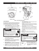
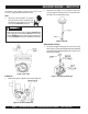
2. Drain the clutch compartment oil (Figure 8) by removing
the magnetic 9 mm (3/8-inch) plug located at the bottom of
the Gear Reduction Assembly.
The Gear Reduction Compartment
consist of two compartments, a lower
and upper. The
lower
compartment
houses the clutch, the
uppe
r
compartment contains the actual gear
reduction. Remember each compartment requires a different
type of lubricating oil.
If the clutch cannot be adjusted, it may
be necessary to inspect or replace the
clutch.
C. When the clutch has been satisfactorily adjusted reinstall
the
adjustment lock
P/N EM 934040 and tighten lock
bolt.
D. Reinstall the
clutch Inspection door
using the six 12 mm
(1/2-inch) cap screws and lock washers, and also check
that the gasket is not worn or broken.
E. Remove the 9 mm (3/8-inch) square head pipe plug located
on the lower clutch compartment. Refill the clutch
compartment with 2.12 liters (2-1/4 quarts) of SAE 30 motor
oil to the level of the plug. When done reinstall plug.
F. Start engine, check for proper clutch engagement and
inspect for any oil leaks.
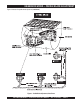
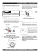
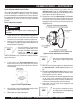
Figure 13. Clutch Adjustment Lock Location
Any questions regarding the above
procedure please contact the Multiquip
Service Department.
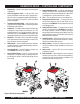
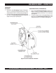
3. To gain access to the "
clutch Inspection door
" remove
the six 12 mm (1/2-inch) cap screws (Figure 12 ) and lock
washers that secure the clutch inspection door. Remove
door and gasket.
Figure 12. Clutch Inspection Door
4. Check that the clutch is disengaged by pulling the shifter
lever towards the engine end of the mixer.
5. Refer to Figure 13 for steps 5A through 5F:
A. Rotate the clutch using the recoil starter until the
adjustment
lock
(Figure 13) P/N EM934040 is visible.
Using a flat blade screwdriver loosen the adjustment bolt
just enough to release the adjustment lock.
B. Using a punch, rotate the
adjusting ring
P/N EM 934045
one notch at a time in the counter-clockwise direction until
a firm 47.45-74.57 N-m (35- 55 lbs.) pressure is felt when
engaging the clutch lever (the lever should snap into the
engaged position).
NOTE
NOTE
NOTE
ALWAYS stop the engine before attempting this
procedure.
CAUTICAUTI
CAUTICAUTI
CAUTION