Operation and Parts Manual MODEL ga6HB/ga6HEB portable generatorS (HONDA GX340R2EDN2/GX340R2EDE2 GASOLINE ENGINES) Revision #0 (03/13/14) To find the latest revision of this publication, visit our website at: www.multiquip.com THIS MANUAL MUST ACCOMPANY THE EQUIPMENT AT ALL TIMES.
Table of Contents GA6HB/GA6HEB Portable 60 Hz Generator Table Of Contents..................................................... 3 Safety Information................................................. 4-8 Specifications (Generator)...................................... 12 Specifications (Engine)........................................... 11 Dimensions............................................................. 12 Installation......................................................... 14-15 General Information.
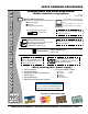
www.multiquip.com parts ordering procedures ordering parts has never been easier! Choose from three easy options: Order via internet (dealers Only): Best deal! Effective: January 1st, 2006 If you have an MQ Account, to obtain a Username and Password, E-mail us at: parts@multiquip. com. Order parts on-line using Multiquip’s SmartEquip website! ■ View Parts Diagrams ■ Order Parts ■ Print Specification Information To obtain an MQ Account, contact your District Sales Manager for more information.
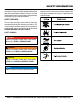
Safety Information Do not operate or service the equipment before reading the entire manual. Safety precautions should be followed at all times when operating this equipment. Failure to read and understand the safety messages and operating instructions could result in injury to yourself and others. Potential hazards associated with the operation of this equipment will be referenced with hazard symbols which may appear throughout this manual in conjunction with safety messages.
Safety Information gENERAl sAFETY CAuTiON NEvER operate this equipment without proper protective clothing, shatterproof glasses, respiratory protection, hearing protection, steel-toed boots and other protective devices required by the job or city and state regulations. AlWAYs know the location of the nearest phone or keep a phone on the job site. Also, know the phone numbers of the nearest ambulance, doctor and fire department. This information will be invaluable in the case of an emergency.
Safety Information ENgiNE sAFETY dANgER The engine fuel exhaust gases contain poisonous carbon monoxide. This gas is colorless and odorless, and can cause death if inhaled. The engine of this equipment requires an adequate free flow of cooling air. NEvER operate this equipment in any enclosed or narrow area where free flow of the air is restricted. If the air flow is restricted it will cause injury to people and property and serious damage to the equipment or engine.
Safety Information NEvER use fuel as a cleaning agent. dO NOT smoke around or near the equipment. Fire or explosion could result from fuel vapors or if fuel is spilled on a hot engine. ElECTRiCAl sAFETY dANgER Make sure power cables are securely connected to the generator’s output receptacles. Incorrect connections may cause electrical shock and damage to the generator. NOTICE AlWAYs make certain that proper power or extension cord has been selected for the job.
Safety Information If the battery liquid (dilute sulfuric acid) comes into contact with clothing or skin, rinse skin or clothing immediately with plenty of water. ENviRONmENTAl sAFETY/dECOmmissiONiNg If the battery liquid (dilute sulfuric acid) comes into contact with eyes, rinse eyes immediately with plenty of water and contact the nearest doctor or hospital to seek medical attention. Decommissioning is a controlled process used to safely retire a piece of equipment that is no longer serviceable.
Safety Information EmissiONs iNFORmATiON NOTICE The gasoline engine used in this equipment has been designed to reduce harmful levels of carbon monoxide (CO), hydrocarbons (HC) and nitrogen oxides (NOx) contained in gasoline exhaust emissions. This engine has been certified to meet US EPA Evaporative emissions requirements in the installed configuration.
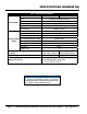
SPECIFICATIONS (gENERATOR) Table 1. Specifications (Generator) Model GA6HB GA6HEB Type Brushless Revolving Field Type Excitation Solid State, Statically Excited System AC Generator Speed 3,600 RPM Cooling System Self-Ventilation Fuel Capacity 5 gallons (19 liters) Continuous Power Output 5.0 kW Max Power Output 6.0 kW Rated Voltage 120/240V 50.0/41.6 amps 60 Hz AC Power Current Max/Continuous (120V) Source Current Max/Continuous (240V) 25.0/20.
SPECIFICATIONS (engine) Table 2. Specifications (Engine) Model HONDA GX340R2EDN2 HONDA GX340R2EDE2 Air-cooled 4 stroke, Single Cylinder, OHV, Horizontal Shaft Type Gasoline Engine 3.46 in. X 2.52 in. Bore X Stroke (88 mm x 64 mm.) Displacement 23.70 cu-in (389 cm3) Engine Max Output 11.0 H.P./3600 R.P.M. Fuel Unleaded Automobile Gasoline Lube Oil Capacity 1.16 quarts (1.1 liters) Oil Alert System Yes Speed Control Method Centrifugal Fly-weight Type Starting Method Recoil Start Electric Start Dimensions 15.
dimensions GA-6HB ON 0N V 120 OFF 120 P O W E R F A U L T IDLE CONTROL AC VOLTMETER OFF OPERATION SWITCH 120V 120/240V A 30A 120 120 30A MANUAL RESET 20A AC CIRCUIT BREAKER GFCI PROTECTED 120V/240V 120V FULL POWER SWITCH 120 V 120 V B 20A 20A IN SIMULTANEOUS USE 30 AMP MAX C D Figure 1. Dimensions Table 3. Generator Dimensions REFERENCE LETTER DESCRIPTION DIMENSIONS: IN. (MM) A HEIGHT (LIFTING BALE) 26.75 (679) B HEIGHT (FRAME) 22.00(560) C LENGTH 27.
note GA6HB/6HEB 60 hz GENERATOR • operation and parts manual — rev.
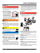
installation Connecting the Ground The nut and ground terminal on the generator should always be used to connect the generator to a suitable ground. The ground cable should be #8 size wire (aluminum) minimum. If copper wire is used, #10 size wire minimum should be used At the generator, connect the terminal of the ground cable between the lock washer and the nut (Figure 2) and tighten the nut fully. Connect the other end of the ground cable to a suitable earth ground (ground rod).
installation Outdoor Installation Generator Grounding If possible install the generator in a area that is free of debris, bystanders, and overhead obstructions. Make sure the generator is on secure level ground so that it cannot slide or shift around. To guard against electrical shock and possible damage to the equipment, it is important to provide a good EARTH ground. The installation site must be relatively free from moisture and dust.
general information FAMILIARIZATION Generator The Multiquip GA6HB/GA6HEB generator is designed as a portable dual purpose power source for 60 Hz (single phase) lighting facilities, power tools, submersible pumps and other industrial and construction machinery. DANGER Before connecting this generator to any building’s electrical system, a licensed electrician must install an isolation (transfer) switch. Serious injury or death may result without this transfer switch.
components (generator) 4 2 3 8 5 6 9 9 7 GA-6HB GA-6HEB ON 0N 0N V 120 F A U L T V 120 ELECTRIC START OFF 120 P O W E R IDLE CONTROL AC VOLTMETER F A U L T 30A 1 120 120 120 MANUAL RESET 30A 20A AC CIRCUIT BREAKER GFCI PROTECTED 30A FULL POWER SWITCH 20A 120 V 120 V 20A 20A IN SIMULTANEOUS USE 30 AMP MAX 13 MANUAL RESET 20A AC CIRCUIT BREAKER GFCI PROTECTED 120V/240V 120V 120 V 12 OPERATION SWITCH 120V 120/240V 120 30A IDLE CONTROL AC VOLTMETER 120V 120/24
components (generator) 15 15 GA-6HB GA-6HEB ON 0N 0N V 120 V 120 F A U L T ELECTRIC START OFF 120 P O W E R IDLE CONTROL AC VOLTMETER 120/240V 30A 120 F A U L T 30A 120 120 MANUAL RESET 30A 20A AC CIRCUIT BREAKER GFCI PROTECTED IDLE CONTROL AC VOLTMETER OPERATION SWITCH 120V 120/240V 120 OFF 120 P O W E R OFF OPERATION SWITCH 120V 30A MANUAL RESET 20A AC CIRCUIT BREAKER GFCI PROTECTED 120V/240V 120V FULL POWER SWITCH 120V/240V 120V START SWITCH FULL POWER SWITCH 120 V
components (generator) 24 25 26 16 17 GA-6H GA-6H 18 20 19 23 21 22 Figure 7. Generator Components (Continued) 16. Fuel Gauge – This gauge is located on top of the fuel tank. Read this gauge to determine when fuel is low. 17. Fuel Tank Cap – Remove this cap to add unleaded gasoline to the fuel tank. Replenish with clean unleaded gasoline. Make sure cap is tightened securely. DO NOT over fill. 18. Fuel Tank – Capacity is 5 gallons (19 liters). Fill with unleaded gasoline. 19.
INSPECTION/SETUP General Inspection Prior to Operation Ground Power Tools When using power tools or electrical equipment requiring AC power from the generator, make sure power tool cord has a ground pin or is double insulated as shown in Figure 8. NOTICE Double-insulated power tools and small appliances have specially insulated housings that eliminate the need for a ground pin.
INSPECTION/setup Before Starting NOTICE ALWAYS place the main circuit breaker in the OFF position prior to starting the engine. 3. Insert and remove the dipstick without screwing it into the filler neck. Check the oil level shown on the dipstick. 4. If the oil level is low (Figure 10), fill to the edge of the oil filler hole with the recommended oil type (Figure 10). Maximum oil capacity is 1.16 quarts (1.1 liters). 1. Read safety instructions at the beginning of manual. 2.
operation This section is intended to assist the operator with the initial start-up of the portable generator. It is extremely important that this section be read carefully before attempting to use the generator in the field. Before Starting the Engine NOTICE Both model generators are equipped with a GFCI sensing module. The purpose of this module is to sense a ground fault during operation of the generator and shut down the generator once the ground fault has been detected.
operation 6. Press the generator's pushbutton start switch (Figure 17) and listen for the engine to start. GA-6HB ON ON OFF Figure 17. Start Switch (GA6HEB Only) 7. If the engine has started, slowly return the choke lever (Figure 14) to the OPEN position. If the engine has not started repeat steps 1 through 6. Figure 19. Idle Control switch (ON) 10. Place main circuit breaker (Figure 20) in the ON position. ON 8. Before the generator is placed into operation, run the engine for 3-5 minutes.
operation/shutdown 12. Read voltmeter on front panel of generator (Figure 22) and verify that 240 VAC is displayed. Using an external voltmeter as shown in Figure 22, verify that 240 VAC is present at the 120/240V, L14-30R twist-lock receptacle. 240VAC 120VAC L14-30R GA-6HEB ON OFF X X 2. Place idle control switch (Figure 24) in the OFF position. L14-30R 120VAC W 120VAC G G W OFF GA-6HB Y Y Figure 24. Idle Control switch (OFF) 3. Let engine run at idle with no load for 2-3 minutes.
preparation for long term storage Generator Storage For storage of the generating set for over 30 days, the following is required: Drain the fuel tank completely, or add STA-BIL to the fuel. Run the engine until the gasoline in the carburetor is completely consumed. Completely drain the oil from the crankcase and refill with fresh oil. Remove the spark plug, pour 2 or 3 cc of SAE 30 oil into the cylinder and crank slowly to distribute the oil.
maintenance Use Table 6 as a general maintenance guideline when servicing your engine. For more detail engine maintenance information, refer to the engine owner's manual supplied with your engine. Table 6. Engine Maintenance Schedule DESCRIPTION (3) Engine Oil Air Cleaner Charcoal Canister (4) All Nuts & Bolts Spark Plug Cooling Fins Spark Arrester Fuel Tank Fuel Strainer Idle Speed Valve Clearance Fuel lines OPERATION CHECK CHANGE CHECK CHANGE EVERY 3 FIRST BEFORE MONTH OR MONTHS 10 HRS. OR 25 HRS.
maintenance Maintenance Spark Plug Perform the scheduled maintenance procedures as defined by Table 5 and below: 1. Remove and clean the spark plug (Figure 28), then adjust the spark gap to 0.024 ~0.028 inch (0.6~0.7 mm). This unit has electronic ignition, which requires no adjustments. Daily Thoroughly remove dirt and oil from the engine and control area. Clean or replace the air cleaner elements as necessary. Check and retighten all fasteners as necessary.
maintenance Engine Air Cleaner spark arrester cleaning DANGER Clean the spark arrester every 6 months or 100 hours. DO NOT use gasoline as a cleaning solvent, the possibility exists of fire or explosion which can cause damage to the equipment and severe bodily harm or even DEATH! 1. Remove the muffler protector retaining bolts (Figure 32), then remove muffler protector. 2. Next, remove tapping screw that secures spark arrestor to muffler, then remove spark arrester. 1.
maintenance battery (ga6HEB) This unit is of negative ground DO NOT connect in reverse. Always maintain battery fluid level between the specified marks. Battery life will be shortened, if the fluid levels are not properly maintained. Add only distilled water when replenishment is necessary. Check to see whether the battery cables are loose. Poor contact may result in poor starting or malfunctions. Always keep the terminals firmly tightened.
maintenance 3. On the GFCI module (Figure 36), verify that the green POWER LED is ON. 240 V 120 F A U L T P O W E R Figure 39. AC Voltmeter (Zero Volts) 8. To restore power, press the RESET button (Figure 40) on the GFCI module and verify that the red FAULT LED turns OFF and the green POWER LED should turn ON GREEN POWER LED MANUAL RESET Figure 36. GFCI Module (Green LED ON) 4. Also verify that the AC voltmeter is registering a voltage reading as indicated by Figure 41. P O W E R 5.
notes GA6HB/6HEB 60 hz GENERATOR • operation and parts manual — rev.
generator wiring diagram (ga6hb) GENERATOR ENGINE SYMBOL Ar Fg-P, N Ex W1 Ex W2 V ~ 4 3 2 1 COLOR CODE WIRE COLOR B BLACK L BLUE BR BROWN G GREEN GR GRAY V VIOLET P PINK WIRE COLOR R RED W WHITE Y YELLOW LB LIGHT BLUE LG LIGHT GREEN O ORANGE CN1 4 3 2 1 CN4 W R 1 2 CN2 CN3 1 2 3 4 CN5 CONNECTOR ARRANGEMENT (VIEW FROM INSERTING WIRE SIDE) DESIGNATION ARMATURE WINDING ROTOR ASSEMBLY EXCITATION WINDING EXCITATION WINDING AC VOLTMETER 120/240V RE 1~2 RECTIFER CB CON 1 CON 2 CON 3 CON 4,5 S
generator wiring digram (ga6heb) GENERATOR ENGINE SYMBOL Ar Fg-P, N Ex W1 Ex W2 V ~ COLOR CODE WIRE COLOR WIRE COLOR B L BR G GR V P BLACK BLUE BROWN GREEN GRAY VIOLET PINK R W Y LB LG O RED WHITE YELLOW LIGHT BLUE LIGHT GREEN ORANGE 4 3 2 1 W R CN1 CN2 1 2 4 5 6 1 2 3 CN4 CN5 A J B C K CN3 6 5 4 3 2 1 CN6 J A K C B CN7 CONNECTOR ARRANGEMENT (VIEW FROM INSERTING WIRE SIDE) DESIGNATION ARMATURE WINDING ROTOR ASSEMBLY EXCITATION WINDING EXCITATION WINDING AC VOLTMETER 120/240V RE 1~
troubleshooting (ENGINE) Troubleshooting (Engine) symptom possible problem Spark plug bridging? Check gap, insulation or replace spark plug. Carbon deposit on spark plug? Clean or replace spark plug. Short circuit due to deficient spark plug insulation? Check spark plug insulation, replace if worn. Improper spark plug gap? Set to proper gap. Fuel reaching carburetor? Check fuel line. Water in fuel tank? Flush or replace fuel tank. Fuel filter clogged? Replace fuel filter.
troubleshooting (ENGINE) Troubleshooting (Engine) - continued symptom Weak in power, compression is proper and does not misfire. Weak in power, compression is proper but misfires. Engine overheats. Rotational speed fluctuates. Recoil starter malfunctions. (if applicable) Starter malfunctions. possible problem Clean or replace air cleaner. Improper level in carburetor? Check float adjustment, rebuild carburetor. Defective spark plug? Clean or replace spark plug.
troubleshooting (GENERATOR) Troubleshooting (generator ) symptom Low voltage Low voltage. Engine speed normal 3650 RPM (unloaded), 2500 RPM (idle) possible problem Engine speed too low? AC voltmeter not working? Control box internal wiring malfunction? Defective ignition coil? Rotor winding malfunction? Stator winding malfunction? Leakage breaker malfunction? Full power switch malfunction? Voltage output too high. Voltage output too high.
notes GA6HB/6HEB 60 hz GENERATOR • operation and parts manual — rev.
Explanation of Code in Remarks Column The following section explains the different symbols and remarks used in the Parts section of this manual. Use the help numbers found on the back page of the manual if there are any questions. NOTICE The contents and part numbers listed in the parts section are subject to change without notice. Multiquip does not guarantee the availability of the parts listed. sAmplE pARTs lisT NO. 1 2% 2% 3 4 pART NO. pART NAmE QTY. REmARks 12345 BOLT .....................1 .....
Suggested Spare Parts GA6HB/GA6HEB portable 60 hZ generator with HONDAGX340R2EDN2/GX340R2EDE2 gasoline engines 1 to 3 units Qty. P/N Description 1............0430430120...........CAP FUEL TANK 1............0605505162...........FILTER FUEL 2............3015419604...........rubber suspension 2............1725419214...........rubber suspension 3............9807955846...........SPARK PLUG 1............35480ZF6003........SWITCH ASSY., OIL ALERT 2............28462ZV7003........ROPE, RECOIL 3............
GA6HB/GA6HEB— nameplate and decalS ASSY. GA6HB GA6HEB DANGER Using a generator indoors CAN KILL YOU IN MINUTES. Utilser un générateur à l’ intérieur VOUS TUERA EN QUELQÙES MINUTES. OPERATING INSTRUCTIONS OPERATING INSTRUCTIONS Before starting check the oil and fuel level. Switch the circuit breaker to the “OFF” position. Open the fuel valve. Pull the choke knob. Turn the operation switch to the “ON” position and push the start button to start the engine. 6.
GA6HB/GA6HEB— nameplate and decals ASSY. NO. 1 2 3 4 5 6 7 8 9 10 11 12 13 14 15 16 PART NO. A5551000004 A9521200104 A9504000014 920214100 D9531100104 0800628504 A9511100103 1980680004 0800696804 87533ZC0630 A5561000603 0800689404 0800689504 87528898620 A5511202002 A5511202302 PART NAME QTY. REMARKS DECAL; OPERATING INSTRUCTIONS (HEB)...1................A55100000 DECAL; OPERATING INSTRUCTIONS (HB).....1................A92120010 DECAL; DANGER, DANGEROUS GASES........1................
GA6HB/GA6HEB — GENERATOR ASSY. page 42 — GA6HB/GA6HEB 60 hz gENERATOR• operation and parts manual — rev.
GA6HB/GA6HEB — GENERATOR ASSY. NO. PART NO. 1 7901002403 1-1# 1-2# 0601823213 0601822638 1-3# 0071706304 2 7901017004 3 0801086104 4 A5135000103 5 7901315502 6 0013608020 6A 0040008000 7 7871315022D 8 7875021523 9 7871331003 10 7901316004 11 7871329514 12 0601851760 PART NAME QTY. REMARKS ROTOR ASSY.....................................................1................INCLUDES ITEMS W/# FIELD ASSY ......................................................1................
GA6HB/GAGHEB — CONTROL BOX ASSY. page 44 — GA6HB/GA6HEB 60 hz gENERATOR• operation and parts manual — rev.
GA6HBGA6HEB — CONTROL BOX ASSY. NO. 1 2 3 4 5 6 6A 7 8 9 10 11 12 13 13A 14 15 16 16A 17 18 19 20 21 22 23 24 24A 25 25A 25B 25C 26 27 PART NO.
GA6HB/GA6HEB — PIPE FRAME ASSY. page 46 — GA6HB/GA6HEB 60 hz gENERATOR• operation and parts manual — rev.
GA6HBGA6HEB — PIPE FRAME ASSY. NO. 1 1A 2 3 4 5 6 7 8 9 9A 10 11 12 13 14 14-1 15 16 17 18 19 20 21 22 23 23A 24 25 25A 25B 26 27 28 29 30 31 32 33 34 35 36 37 38 39 40 41 PART NO.
GA6HEB — BATTERY ASSY. page 48 — GA6HB/GA6HEB 60 hz gENERATOR• operation and parts manual — rev.
GA6HEB — BATTERY ASSY. NO. PART NO. 32 33 7905458103 34 A5344200004 35 0037806000 36 0040006000 37 0041206000 38 A5347000504 38A D1343200604 39 A5347000004 38B Y0602220643 PART NAME QTY. REMARKS BATTERY............................................................1................
GA6HB/GA6HEB — MUFFLER ASSY. page 50 — GA6HB/GA6HEB 60 hz gENERATOR• operation and parts manual — rev.
GA6HB/GA6HEB — MUFFLER ASSY. NO. 1 2 3 4 5 6 7 8 9 10 11 12 13 13A 14 15 16 16A 17 PART NO. W7912310003 18320ZC2000 18325ZB4000 18329ZB4000 18355ZB4630 Y0602322011 0105050616 18333ZB4801 Y0602322010 W7905461004 011008020 W7905460004 011208025 020108060 011008020 W7905469004 011206020 020108060 0105050616 PART NAME QTY. REMARKS MUFFLER 1 PROTECTOR 1 PROTECTOR 1 SEAL 2 ARRESTOR, SPAR 1 TAPPPING SCREW 1 HEX. HEAD BOLT ..............................................5................
HONDA GX340R2EDE2/EDN2 — AIR CLEANER ASSY. page 52 — GA6HB/GA6HEB 60 hz gENERATOR• operation and parts manual — rev.
HONDA GX340R2EDE2/EDN2 — AIR CLEANER ASSY. NO. 1 2 3 4 5 6 7 8 9 10 11 13 13 PART NO.
HONDA GX340R2EDE2/EDN2 — CAMSHAFT ASSY. page 54 — GA6HB/GA6HEB 60 hz gENERATOR• operation and parts manual — rev.
HONDA GX340R2EDE2/EDN2 — CAMSHAFT ASSY. NO. 1 2 3 4 5 6 7$ 8 9 10 11 12 13 14 15 16 17 PART NO. 12209ZE8003 14100Z5K810 14410ZE3013 14431ZE2010 14441ZE2000 14451ZE1013 14568ZE1000 14711Z5T000 14721Z5T000 14751ZE2003 14771ZE2000 14773ZE2000 14775ZE2010 14781ZE2000 14791ZE2010 90012ZE0010 90206ZE1000 PART NAME QTY. REMARKS SEAL VALVE STEM 1 CAMSHAFT ASSY..............................................1................
HONDA GX340R2EDE2/EDN2 — CARBURETOR ASSY. page 56 — GA6HB/GA6HEB 60 hz gENERATOR• operation and parts manual — rev.
HONDA GX340R2EDE2/EDN2 — CARBURETOR ASSY. NO. 1$+♦♣@ 2$ 3$ 4$% 5$ 6$%@ 7$% 8 9$ 10$ 11$ 12$ 14 15 17$ 18 19# 20# 21# 22# 23# 24# 25 26# 27# 28# 29# 30 31# 32 33# 34# 35# 36# 37 39# 40$ 41 42# 43# 44# 45# 47 49 50 51$ 51$ 52$ 54 PART NO.
HONDA GX340R2EDE2/EDN2 — CONTROL ASSY. page 58 — GA6HB/GA6HEB 60 hz gENERATOR• operation and parts manual — rev.
HONDA GX340R2EDE2/EDN2 — CONTROL ASSY. NO. 1 3 4 5 8 16$ 20 21 28$ 30 PART NO. 16550ZE3700 16555ZE3000 16561ZK6D70 16562ZE3700 16570Z5T880 16584883300 90013883000 90015ZE5010 93500050350A 9405006000 PART NAME QTY. REMARKS ARM, GOVERNOR 1 ROD, GOVERNOR 1 SPRING, GOVERNOR 1 SPRING, THROTTLE RETURN 1 CONTROL ASSY................................................1................
HONDA GX340R2EDE2/EDN2 — CRANKCASE COVER ASSY. page 60 — GA6HB/GA6HEB 60 hz gENERATOR• operation and parts manual — rev.
HONDA GX340R2EDE2/EDN2 — CRANKCASE COVER ASSY. NO. 1 2 3 4 5%@ 6$ 7#$ 8#$ 9#$ 10$ 11$ 12 13$ 14$ 15 16$ 17$ PART NO. 11300ZE3040 11381Z5T000 15600ZG4003 15600735003 15625ZE1003 16510ZE3000 16511ZE8000 16512ZE3000 16513ZE2000 16531ZOA000 90602ZE1000 90701HC4000 91201ZE3004 9410106800 957010804000 961006202000 961006207000 PART NAME QTY. REMARKS COVER ASSY., CRANKCASE............................1................INCLUDES ITEMS W/$ PACKING CRANKCASE COVER 1 CAP ASSY., OIL FILLER...............................
HONDA GX340R2EDE2/EDN2 — CRANKSHAFT ASSY. page 62 — GA6HB/GA6HEB 60 hz gENERATOR• operation and parts manual — rev.
HONDA GX340R2EDE2/EDN2 — CRANKSHAFT ASSY. NO. 8 13# 14 PART NO. 13351ZE3010 961001ZF6013 13310ZF6D42 PART NAME QTY. REMARKS WEIGHT, BALANCER 1 BEARING, RADIAL BALL (6207) 1 CRANKSHAFT COMP.........................................1................INCLUDES ITEM W/# GA6HB/6HEB 60 hz GENERATOR • operation and parts manual — rev.
HONDA GX340R2EDE2/EDN2 — CylINDER BARREL ASSY. page 64 — GA6HB/GA6HEB 60 hz gENERATOR• operation and parts manual — rev.
HONDA GX340R2EDE2/EDN2 — CylINDER BARREL ASSY. NO. 1 1 2 3 7 8 10$# 11$# 12 13 14 15 16 17$# PART NO. 12000Z5T405 12000Z5T407 35480ZF6003 16541ZE3010 90131896650 90446KE1000 91201Z1C003 91201ZE9003 91353671003 9405010000 031112230 9425110000 957010601200 961006202000 PART NAME QTY. REMARKS BARREL ASSY, ELECTRIC START....................1................INCLUDES ITEMS W/$ BARREL ASSY, RECOIL START........................1................INCLUDES ITEMS W/# SWITCH ASSY.
HONDA GX340R2EDE2/EDN2 — CylINDER HEAD ASSY. page 66 — GA6HB/GA6HEB 60 hz gENERATOR• operation and parts manual — rev.
HONDA GX340R2EDE2/EDN2 — CylINDER HEAD ASSY. NO. 1 2$ 3$ 4$ 5 6 8 10 11 12 13 14 15 16 16 PART NO. 12210Z5T406 12204ZE2306 12205ZE2305 12216ZE2300 12251Z5T003 12310Z5T000 12391ZE2020 90014ZE2000 90042ZK6D70 92900080320E 90441ZE2010 9430112200 957011008000 9807955846 9807955855 PART NAME QTY. REMARKS CYLINDER HEAD...............................................1................INCLUDES ITEMS W/$ GUIDE, VALVE (OS) (OPTIONAL) 1 GUIDE, EX.
HONDA GX340R2EDE2/EDN2 — FAN COVER ASSY. page 68 — GA6HB/GA6HEB 60 hz gENERATOR• operation and parts manual — rev.
HONDA GX340R2EDE2/EDN2 — FAN COVER ASSY. NO. 2 4 8 10 11 PART NO. 19610Z5T800ZC 19631Z5T000 81329567020 90013883000 90654SA4003 PART NAME COVER, FAN *NH1* (BLACK) SHROUD GROMMET, DRAIN HOLE BOLT, FLANGE (6X12) (CT200) CLIP, WIRE HARNESS (6MM) (WHITE) QTY. 1 1 1 6 2 REMARKS GA6HB/6HEB 60 hz GENERATOR • operation and parts manual — rev.
HONDA GX340R2EDE2/EDN2 — FLYWHEEL ASSY. page 70 — GA6HB/GA6HEB 60 hz gENERATOR• operation and parts manual — rev.
HONDA GX340R2EDE2/EDN2 — FLYWHEEL ASSY. NO. 1 4 8 8 10 11 PART NO. 19511ZE3000 28451ZE3W01 31100Z5T810 31100Z5T820 90201ZE3790 90741ZE2000 PART NAME FAN, COOLING PULLEY, STARTER FLYWHEEL COMP., (RECOIL STRART) FLYWHEEL COMP., ELECTRIC START NUT, SPECIAL 16MM KEY, SPECIAL WOODRUFF (25X18) QTY. 1 1 1 REMARKS 1 1 GA6HB/6HEB 60 hz GENERATOR • operation and parts manual — rev.
HONDA GX340R2EDE2/EDN2 — IGNITION COIL ASSY. page 72 — GA6HB/GA6HEB 60 hz gENERATOR• operation and parts manual — rev.
HONDA GX340R2EDE2/EDN2 — IGNITION COIL ASSY. NO. 2 3 4 5 10 11 13 14 15 16 25 PART NO. 30700ZE1013 31510ZE3003 31511ZE3000 31512ZE2000 90012888000 90013883000 90015883000 90684ZA0601 30500Z5R003 31510ZE1811 32110Z5K000 PART NAME CAP ASSY., NOISE SUPPRESSOR COIL ASSY., LAMP (12V/25W) CLAMP, WIRE GROMMET, WIRE BOLT, FLANGE (6X40) BOLT, FLANGE (6X12) (CT200) BOLT, FLANGE (6X28) CLIP, HARNESS, RECOIL START COIL ASSY., IGNITION COIL ASSY., LAMP (12V/25W) HARNESS ASSY., ENGINE WIRE QTY.
HONDA GX340R2EDE2/EDN2 — PISTON ASSY. page 74 — GA6HB/GA6HEB 60 hz gENERATOR• operation and parts manual — rev.
HONDA GX340R2EDE2/EDN2 — PISTON ASSY. NO. 1 1 1 1 2 2 2 2 3 4 5$ 6 PART NO. 13010Z5R004 13011Z5R004 13012Z5R004 13013Z5R004 13101Z5T800 13102Z5T800 13103Z5T800 13104Z5T800 13111Z5T000 13200ZE3020 90001ZE8000 90601ZE3000 PART NAME QTY. REMARKS RING SET, PISTON (STD) 1 RING SET, PISTON (OS 0.25) (OPTIONAL) 1 RING SET, PISTON (OS O.50) (OPTIONAL) 1 RING SET, PISTON (0.75) (OPTIONAL) 1 PISTON (STD) 1 PISTON (0.25) 1 PISTON (0.50) 1 PISTON (0.75) 1 PIN, PISTON 1 ROD ASSY., CONNECTING (STD)....................
HONDA GX340R2EDE2/EDN2 — recoil starter ASSY. page 76 — GA6HB/GA6HEB 60 hz gENERATOR• operation and parts manual — rev.
HONDA GX340R2EDE2/EDN2 — recoil starter ASSY. NO. PART NO. 1 28400Z5T305ZB 2$ 28410ZE3W01ZB 3$ 28421ZE3W01 4$ 28422ZE2W01 5$ 28441ZE2W01 6$ 28442ZE2W01 7$ 28443ZE2W01 8$ 28444ZE2W01 10$ 28462ZV7003 11$ 90004ZE2W01 12 90008ZE2003 13$ 28461Z5T003 14$ 28463Z5T003 PART NAME QTY. REMARKS STARTER ASSY., RECOIL *NH1* (BLACK).......1................INCLUDES ITEMS W/$ ..............................................................................................
HONDA GX340R2EDE2 — starter Motor ASSY. page 78 — GA6HB/GA6HEB 60 hz gENERATOR• operation and parts manual — rev.
HONDA GX340R2EDE2 — starter Motor ASSY. NO. 1$ 2$ 3$ 4 5$ 6$ 7$ 8$ 9$ 10$ 11$% 12$ 14$ 15$ 16$# 18$ 19$ 20$ 21$ 22 PART NO. 31204ZA0003 31206ZE3003 31207ZE3003 31210ZE3023 31211ZE2003 31212ZE3003 31213ZE2003 31215ZE2003 31218ZE3003 31219ZE2003 31222ZE3791 31231ZE2003 31232ZE3003 31233ZE2003 90110ZE2003 91601ZE2003 90007ZE2003 938920503218 9407006080 957010803508 PART NAME QTY. REMARKS CONTACTOR ASSY. 1 ARMATURE COMPLETE 1 CLUTCH, OVERRUNNING.................................1................
HONDA GX340R2EDE2/EDN2 — SOLENOID ASSY. page 80 — GA6HB/GA6HEB 60 hz gENERATOR• operation and parts manual — rev.
HONDA GX340R2EDE2/EDN2 — SOLENOID ASSY. NO. 1 2 3 4 5 PART NO. 16268893000 17850ZD1E30 36160ZB4013 90013883000 93500050080A PART NAME SPRING, CHOKE RETURN LEVER, THROTTLE SOLENOID ASSY. BOLT, FLANGE (6X12) SCREW, PAN (5X8) QTY. 1 1 1 1 2 REMARKS GA6HB/6HEB 60 hz GENERATOR • operation and parts manual — rev.
HONDA GX340R2EDE2/EDN2 — ENGINE DECALS ASSY. page 82 — GA6HB/GA6HEB 60 hz gENERATOR• operation and parts manual — rev.
HONDA GX340R2EDE2/EDN2 — ENGINE DECALS ASSY. NO. 1 2 3 4 PART NO. 87533ZC0630 87528898620 87594ZB4A00 87521Z8T000 PART NAME DECAL, AIR CLEANER DECAL, CHOKE MARK, OIL CAUTION EMBLEM (GX340) QTY. 1 1 1 1 REMARKS GA6HB/6HEB 60 hz GENERATOR • operation and parts manual — rev.
Terms and Conditions of Sale — Parts pAYmENT TERms 5. Parts must be in new and resalable condition, in the original Multiquip package (if any), and with Multiquip part numbers clearly marked. 6. The following items are not returnable: Multiquip reserves the right to quote and sell direct to Government agencies, and to Original Equipment Manufacturer accounts who use our products as integral parts of their own products. a. spECiAl EXpEdiTiNg sERviCE Terms of payment for parts are net 30 days.
notes GA6HB/6HEB 60 hz GENERATOR • operation and parts manual — rev.
Operation and Parts Manual HERE’S HOW TO GET HELP PLEASE HAVE THE MODEL AND SERIAL NUMBER ON-HAND WHEN CALLING UNITED STATES Multiquip Corporate Office 18910 Wilmington Ave. Carson, CA 90746 Contact: mq@multiquip.com MQ Parts Department Tel.