Operation and Parts Manual GloBug SERIES MODEL GBC/GBCE cart type lighting system Revision #1 (03/25/14) To find the latest revision of this publication, visit our website at: www.multiquip.com THIS MANUAL MUST ACCOMPANY THE EQUIPMENT AT ALL TIMES.
proposition 65 warning page 2 — GBC/GBCE lighting system • operation and parts manual — rev.
Table of Contents GBC/GBCE Lighting System Proposition 65 Warning............................................ 2 Table Of Contents..................................................... 3 Parts Ordering Procedures....................................... 4 Safety Information................................................. 5-9 Specifications......................................................... 10 Dimensions............................................................. 11 Footcandle Plot.....................
www.multiquip.com Parts Ordering Procedures ordering parts has never been easier! Choose from three easy options: order via internet (dealers only): Best deal! Effective: January 1st, 2006 If you have an MQ Account, to obtain a Username and Password, E-mail us at: parts@multiquip. com. Order parts on-line using Multiquip’s SmartEquip website! ■ View Parts Diagrams ■ Order Parts ■ Print Specification Information To obtain an MQ Account, contact your District Sales Manager for more information.
Safety Information Do not operate or service the equipment before reading the entire manual. Safety precautions should be followed at all times when operating this equipment. Failure to read and understand the safety messages and operating instructions could result in injury to yourself and others. Potential hazards associated with the operation of this equipment will be referenced with hazard symbols which may appear throughout this manual in conjunction with safety messages.
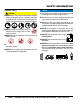
Safety Information general saFety Caution never operate this equipment without proper protective clothing, shatterproof glasses, respiratory protection, hearing protection, steel-toed boots and other protective devices required by the job or city and state regulations. never operate this equipment when not feeling well due to fatigue, illness or when under medication. never operate this equipment under the influence of drugs or alcohol.
Safety Information lighting system saFety Warning never disconnect any emergency or safety devices. These devices are intended for operator safety. Disconnection of these devices can cause severe injury, bodily harm or even death. Disconnection of any of these devices will void all warranties. Caution never attempt service on a running machine. NOTICE To prevent the lighting system from overturning, never use in winds that exceed 22 mph (10 m/s).
Safety Information Balloon saFety Warning To prevent serious burns, never touch or unzip the balloon envelope when the lamp is on. Caution ALWAYS keep the balloon away from sharp objects and excessive amounts of heat. NOTICE To prevent balloon deformation, never use lighting system in strong winds. do not place the balloon inside its protective cover until the lamp has had a sufficient amount of time to cool down.
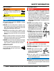
SAFETY INFORMATION LOADING AND UNLOADING Cart Type - No Lifiting Hook Cart Type - With Lifiting Hook If lighting system is not equipped with a transport lifting hook and the mast is removable, refer to the following safety information. If lighting system is equipped with a transport lifting hook, refer to the following safety information. CAUTION Before lifting, make sure that the mast and lamp are removed as described in the manual.
Specifications Table 1. Specifications Model Input Voltage Max.
dimensions G D C E A B F Figure 1. GBC/GBCE Dimensions Reference Letter A B Table 2. Dimensions Description Cart Width Cart Length C Total Max. Height (with Standard Balloon) D E F G Standard Balloon Height Mast Height (without Balloon) Cart Height Standard Balloon Diameter Dimension inches (mm) 27.6 (700) 40.5 (1,029) GBC -127.3 (3,233) GBCE - 180.7 (4,590) 28.3 (718.8) 99 (2,515) 12 (305) 47.2 (1,200) gbc/GBCE lighting system • operation and parts manual — rev.
footcandle plot .25 .5 1 2 5 10 VALUES LISTED AS FOOTCANDLES SCALE: 1 GRID = 50 FT. (15.24 METERS) Figure 2. Illumination Range page 12 — GBC/GBCE lighting system • operation and parts manual — rev.
general information The Multiquip GBC/GBCE Lighting System is a general purpose floodlight tower intended for emergency and remote lighting needs. It is universally adaptable to all AC power supplies and accepts 50/60 Hz, 100-240 V. The GBC/GBCE uses a single 1,000 watt lamp with pure white light for maximum illumination with a light coverage of up to 150 feet. The standard balloon (GBP) that comes with the GBC/GBCE provides 360° glarefree illumination.
components 19 1 2 25 20 18 3 24 4 17 23 16 5 22 15 21 14 6 7 8 26 13 12 10 9 11 GBCE ONLY Figure 3. GBC/GBCE Components page 14 — GBC/GBCE lighting system • operation and parts manual — rev.
components Figure 3 shows the location of the controls and components for the GBC/GBCE Lighting System. The functions of each control is described below: 13. Brake Pedal — Step on this pedal and pull back T-handle to apply the brakes. To release the brakes, press down and hold brake pedal again then release. 1. Balloon Cover — Stores balloon when GBC/GBCE is not in use. Allow a sufficient amount of time for the lamp to cool down before storing balloon. Possibility exists of balloon getting burned. 14.
setup 1. Set the GBC/GBCE cart on a firm level surface where there is enough space around the cart for the outriggers to be deployed. 5. Insert the balloon assembly into the mast. Tighten the T-bolt securely. See Figure 7. 2. Insert the T-handle into the handle holder on the cart. Tighten with the wing bolt. See Figure 4. BALLOON PROTECTIVE COVER T-HANDLE T-BOLT MAST Figure 7. Installing the Balloon 6. Unsnap the three buttons on the bottom of the balloon cover and unzip the cover. See Figure 8. 7.
setup 9. Connect the power cable to the lamp cable connector. See Figure 10. LAMP CABLE CONNECTOR POWER CABLE CONNECTOR Figure 10. Connecting the Power Cable 10. Secure the power cable by hooking it to the eyelet on the bottom of the balloon as shown in Figure 11. CABLE HOOK Figure 11. Securing Cable with Hook 11. Release the buckle on the belt holding the balloon together. See Figure 12. BUCKLE Figure 12. Releasing Buckle gbc/GBCE lighting system • operation and parts manual — rev.
operation APPLYING PARKING BRAKE deploying outrigger 1. Step on the brake pedal while pulling on the T-handle until the brake pedal is all the way down. See Figure 13. 1. Pull up the counterweight that holds the outrigger in place and pull the outrigger all the way out. See Figure 15. COUNTERWEIGHT OUTRIGGER BRAKE Figure 13. Applying Brake releasing PARKING BRAKE 1. Step on the brake pedal, hold then release. See Figure 14.
operation STOWING OUTRIGGER raising the mast 1. Pull up the counterweight to unlock the outrigger and pull up outrigger. See Figure 17. PULL UP COUNTERWEIGHT PULL UP OUTRIGGER DANGER ALWAYS make sure the area above the lighting system is open and clear of overhead power lines and other obstructions. Contact with overhead power lines or other obstructions could result in equipment damage, electrical shock, electrocution and even death.
operation LOWERING THE MAST NOTICE 1. Loosen the T-bolt holding the second mast and push mast all the way down. Tighten T-bolt securely. See Figure 21. SECOND MAST If the power cable is accidentally unplugged from the power source, wait three to five minutes before reconnecting the power. This will allow time for the fan to reset and ensure balloon will inflate properly when power is reconnected. SHUTDOWN 1. Turn off the power switch of the generator. 2. Disconnect the AC power cable from the generator.
operation NOTICE To turn lamp back on, unplug the power cable from the power source. Wait three to five minutes before reconnecting the power. Reconnect the power cable and the lamp should turn on and the balloon will inflate. STORAGE Before storing the GBC/GBCE Lighting System, perform the following steps. NOTICE Allow about 15 to 20 minutes for the lamp to cool down before storing the GBC/GBCE. The possibility exists of the balloon getting burned if it touches a hot lamp. 1.
maintenance REPLACING LAMP 3. Remove the lamp guard. DANGER Never attempt to replace lamp in a wet place. The possibility exists of electric shock. 4. Press the tabs on the lamp holder and push up lamp holder to release it from lamp. See Figure 28. WARNING Always allow sufficient time for the lamp to cool down before replacing. The possibility exists of severe burns if hot lamp is touched.
maintenance NOTICE Do not use excessive force when screwing the lamp to prevent lamp from breaking. 3. Slide in the new replacement balloon over the top of the lamp guard assembly. See Figure 33. 7. Secure lamp holder on top of the lamp. 8. Reinstall lamp guard. 9. Pull down balloon and zip the bottom zipper to cover lamp. INSTALL NEW BALLOON REPLACING BALLOON 1. Unzip the top and bottom of the balloon. See Figure 31. Figure 33. Replacing Balloon 4. Zip up the top and bottom of the new balloon.
maintenance filter replacement 5. Install a new filter and reinstall the air plate. 1. Remove the balloon as described in the STORAGE section. 6. Turn the three locking tabs inwards to lock the air plate in place. See Figure 37. 2. Turn the balloon/lamp assembly upsidedown to access the filter. See Figure 35. LOCK TAB AIR PLATE LOCKING TAB Figure 37. Locking Air Plate Figure 35. Accessing Filter 3. Turn the three locking tabs outwards to release the air plate. See Figure 35. 4.
maintenance SYMPTOM Lamp does not light. Lamp only lights for a short time. Balloon does not inflate. Table 4.
maintenance B2 B1 L3 L5 L4 L1 L2 L3 B4 B3 M1 E1 B5 M2 L2 C10 C5 C8 C1 C7 C4 C2 C3 C11 E2 C6 C9 C1 Figure 38. Maintenance Check Points page 26 — GBC/GBCE lighting system • operation and parts manual — rev.
maintenance Table 5.
wiring diagram POWER CABLE (120 VAC INPUT) GRN/YEL 10 AWG 1000 WATT METAL HALIDE LAMP G LINE NEUTRAL RED BLACK BLACK WHITE WHITE WHITE GRN/YEL BLACK WHITE ELECTRONIC BALLAST RED BLACK 3 GRN/YEL 1 2 BLK 1 BLK 2 CONNECTOR (FEMALE) FRONT VIEW CONNECTOR (MALE) TABLE 3 REFERENCE DESIGNATIONS BLACK WHITE BLACK GRN/YEL RED FAN MOTOR page 28 — GBC/GBCE lighting system • operation and parts manual — rev.
notes gbc/GBCE lighting system • operation and parts manual — rev.
Explanation of Code in Remarks Column The following section explains the different symbols and remarks used in the Parts section of this manual. Use the help numbers found on the back page of the manual if there are any questions. NOTICE The contents and part numbers listed in the parts section are subject to change without notice. Multiquip does not guarantee the availability of the parts listed. sample parts list no. 1 2% 2% 3 4 part no. part name Qty. remarKs 12345 BOLT .....................1 .....
Suggested Spare Parts GBC/GBCE lIGHTING SYSTEM 1 to 3 units Qty. P/N Description 2............E000080700..........LAMP 2............A300168900..........E BALLAST ASSY 2............GBB115DR............BALLOON CLOTH CP 3............2214500430...........FILTER NOTICE Part numbers on this Suggested Spare Parts list may supersede/replace the part numbers shown in the following parts lists. gbc/GBCE lighting system • operation and parts manual — rev.
nameplates and decals 1 To prevent breaking, NEVER use in strong winds that makes balloon deformed considerably. the lighting system. 9 GloBug Lighting System TM A-4001938-00 2 2 4 3 SETTING : Pull upward the lever. Grab hold of outrigger, pull outward until it stops. Pull downward until it touches the ground. Pull downward the lever. 8 ALWAYS apply the parking brake to prevent rolling. APPLYING : Step on the brake pedal and pull back on the T-handle. RELEASE : Pull upward the lever.
nameplates and decals NO. PART NO. PART NAME QTY. REMARKS 1 A400193800 DECAL; GLOBUG INFORMATION 1 2 A400193400 DECAL; RELEASE 3 3 A400193700 DECAL; WARNING, PARKING BRAKE 1 4 A400193500 DECAL; PULL 3 5 A400194000 DECAL; CAUTION, LAMP INFORMATION 1 6 A400193900 DECAL; LAMP OFF SWITCH 1 7 A400166800 DECAL; ELECTRIC SHOCK, HIGH VOLTAGE, BURN HAZ.....1........ DCL1261 8 A400193600 DECAL; WARNING, OUTRIGGER DEPLOYMENT 1 9 A400193300 DECAL; GLOBUG LIGHTING SYSTEM 1 10 NAMEPLATE.................................
balloon and lamp assy OPTIONAL BALLOONS AND MESSAGE STRIPS 47 42 17 45 48 49 16 19 15 20 19A 21 50 14 23 22 51 13 20 25 4 4 52 12 26 27 24 28 51 18 44 11 4 8 41 29 3 12 40 30 15 27 31 32 33 43 35 36 37 3 34 39 10 1 7 6 10 5 4 38 4 2 46 3 4 9 page 34 — GBC/GBCE lighting system • operation and parts manual — rev.
balloon and lamp assy NO. PART NO. PART NAME QTY.
MAST assy 1 26 2 25 4 22 12 16 3 7 27 7 8 17 15 12 13 12 14 13 11 13 12 13 12 24 23 17 21 20 13 18 19 9 10 6 5 page 36 — GBC/GBCE lighting system • operation and parts manual — rev.
MAST assy NO. 1 2 3 4 5 6 7 8 9 10 11 12 13 14 15 16 17 18 19 20 21 22 23 24 25 26 27 PART NO.
BASE assy 24 23 29 22 1 29 21 7 6 25 5 21 27 26 8 5 6 8 7 28 9 8 2 11 13 5 28 8 4 14 10 3 7 6 12 20 6 19 14 8 5 13 8 12 15 16 28 17 18 8 8 page 38 — GBC/GBCE lighting system • operation and parts manual — rev.
BASE assy NO. 1 2 3 4 5 6 7 8 9 10 11 12 13 14 15 16 17 18 19 20 21 22 23 24# 25 26 27 28 29 PART NO. A100054500 A300147201 A300147301 A300056800 0053512000 0043112000 1504120130 0040720000 A300137101 A300150900 1521120131 2071214010 A400189600 1503180130 0013212075 0010308030 2001200313 0043108000 0033108000 1041000131 1503300130 0040730000 A200023001 1102700130 A400176500 0014212025 0043112041 E000014500 1652000430 PART NAME QTY.
OUTRIGGER assy 15 14 5 4 15 14 10 6 7 16 3 9 17 2 1 8 12 12 11 11 7 3 6 1 10 5 13 7 8 4 9 12 9 11 1 6 4 10 5 3 2 8 page 40 — GBC/GBCE lighting system • operation and parts manual — rev.
OUTRIGGER assy NO. 1 2 3 4 5 6 7 8 9 10 11 12 13 14 15 16 17 PART NO.
Terms and Conditions of Sale — Parts The following section explains the different symbols and remarks used in the Parts section of this manual. Use the help numbers found on the back page of the manual if there are any questions. NOTICE The contents and part numbers listed in the parts section are subject to change without notice. Multiquip does not guarantee the availability of the parts listed. sample parts list no. 1 2% 2% 3 4 part no. part name Qty. remarKs 12345 BOLT .....................1 .....
notes gbc/GBCE lighting system • operation and parts manual — rev.
Operation and Parts Manual HERE’S HOW TO GET HELP PLEASE HAVE THE MODEL AND SERIAL NUMBER ON-HAND WHEN CALLING UNITED STATES Multiquip Corporate Office 18910 Wilmington Ave. Carson, CA 90746 Contact: mq@multiquip.com MQ Parts Department Tel.