
user manual


PAGE 14 — MLT25 SERIES LIGHT TOWER • OPERATION MANUAL — REV. #0 (11/28/12)
COMPONENTS
1
2
3
5
5
4
6
9
8
7
10
11
12
13
14
15
16
17
18
18
19
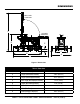
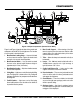
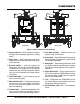
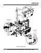
Figure 2 and Figure 3 show the location of the controls and
components for the MLT25 Series light tower. The function
of each control is described below.
1. Mast Rotation Locking Knob — Unscrew this knob
to release mast for rotation. Tighten this knob to lock
mast after it is set to the desired position.
2. Mast Extension Winch — Use this winch to extend
the mast to the desired height. Maximum height is
approximately 31.5 feet (9.6 meters).
3. Mast Rotation Handles — Grip these handles to rotate
mast to desired position.
4. Lifting Bale — Light tower can be lifted using this lifting
bale. The lifting bale is balanced for a fully configured
light tower. Removal of any components will unbalance
the lifting bale.
5. Forklift Pockets — Light tower can be lifted using
these forklift pockets. Insert the forks of the forklift as
far possible into the pockets.
6. Mast Cradle Support — When towing of the light
tower is required, place the tower mast into the cradle
support. Make sure cradle lock/release pin has been
inserted and mast is locked.
7. T-Bar — Allows the lamps to be mounted vertically or
horizontally.
8. Lamps — Six 1000-watt metal-halide bulbs with a
110,000 lumens capacity each. Light coverage is
typically between 5 to 7 acres.
9. Cradle Lock/Release Pin — Locks mast in cradle
support and releases mast when removed.
10. Rear Jackstands — There are two jackstands located
at the rear of the trailer. Use these jackstands to level
and support the light tower.
11. Chock Blocks — Place these blocks (not included
as part of the light tower package) under each trailer
wheel to prevent rolling.
12. Outrigger Jacks — Use these 2 outrigger jacks to
level and support the light tower. For more stability, the
outriggers can be deployed.
Figure 2. Major Components (Control Panel Side)