OPERATION AND PARTS MANUAL SERIES MODEL LS300 CONCRETE PUMP (DEUTZ TD2009L04 DIESEL ENGINE) Revision #4 (06/21/10) To find the latest revision of this publication, visit our website at: www.multiquip.com THIS MANUAL MUST ACCOMPANY THE EQUIPMENT AT ALL TIMES.
PROPOSITION 65 WARNING Diesel engine exhaust and some of PAGE 2 — MAYCO LS300 CONCRETE PUMP • OPERATION AND PARTS MANUAL — REV.
NOTES MAYCO LS300 CONCRETE PUMP • OPERATION AND PARTS MANUAL — REV.
TABLE OF CONTENTS Mayco LS300 Concrete Pump Proposition 65 Warning .............................................2 Table of Contents ......................................................4 Parts Ordering Procedures .......................................5 Safety Message Alert Symbols ............................. 6-7 Rules for Safe Operation .................................... 8-10 Specifications ..........................................................12 Dimensions ........................................
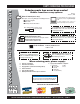
www.multiquip.com PARTS ORDERING PROCEDURES Ordering parts has never been easier! Choose from three easy options: Order via Internet (Dealers Only): Best Deal! Effective: January 1st, 2006 If you have an MQ Account, to obtain a Username and Password, E-mail us at: parts@multiquip. com. Order parts on-line using Multiquip’s SmartEquip website! N View Parts Diagrams N Order Parts N Print Specification Information To obtain an MQ Account, contact your District Sales Manager for more information.
SAFETY MESSAGE ALERT SYMBOLS FOR YOUR SAFETY AND THE SAFETY OF OTHERS! Safety precautions should be followed at all times when operating this equipment. Failure to read and understand the Safety Messages and Operating Instructions could result in injury to yourself and others. This Owner's Manual has been developed to provide complete instructions for the safe and efficient operation of the Multiquip Mayco LS300 Concrete pump.
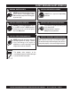
SAFETY MESSAGE ALERT SYMBOLS WARNING - ROTATING PARTS NEVER operate equipment with covers, or guards removed. Keep fingers, hands, hair and clothing away from all moving parts to prevent injury. CAUTION - ACCIDENTAL STARTING ALWAYS place the Engine ON/OFF switch in the OFF position. NEVER perform maintenance on the unit with the ignition key in the ON position. CAUTION - OVER-SPEED CONDITIONS NEVER tamper with the factory settings of the engine governor or settings.
RULES FOR SAFE OPERATION DANGER - READ OPERATION AND PARTS Failure to follow instructions in this manual may lead to serious injury or even death! This equipment is to be operated by trained and qualified personnel only! This equipment is for industrial use only. The following safety guidelines should always be used when operating the LS300 concrete pump: GENERAL SAFETY ■ DO NOT operate or service this equipment before reading this entire manual.
RULES FOR SAFE OPERATION ■ NEVER run engine without air filter. Severe engine damage may occur. ■ ALWAYS be sure the operator is familiar with proper safety precautions and operation techniques before using pump. ■ ALWAYS store equipment properly when it is not being used. Equipment should be stored in a clean, dry location out of the reach of children. ■ DO NOT operate this equipment unless the hopper grate, guards and safety devices are attached and in place.
RULES FOR SAFE OPERATION BATTERY EMERGENCIES The battery contains acids that can cause injury to the eyes and skin. To avoid eye irritation, always wear safety glasses. Use well insulated gloves when picking up the battery. Use the following guidelines when handling the battery: ■ ALWAYS know the location of the nearest fire extinguisher. ■ ALWAYS know the location of the nearest and first aid kit. ■ DO NOT drop the battery. There is the possibility of risk that the battery may explode.
NOTES MAYCO LS300 CONCRETE PUMP • OPERATION AND PARTS MANUAL — REV.
SPECIFICATIONS TABLE 1. PUMP SPECIFICATIONS Model LS300 Pumping Rate Up to 30 cu. yds. per hour* Pumping Method Reciprocating Piston Maximum Aggregate Size 1-1/2 in. minus (38mm) Ver tical Pumping Height Up to Excess of 200 ft. (60.9 m) Piston Face Pressure 800 PSI (55.16 bar) Horizontal Pumping Distance 800 ft. (243m)* Cylinder Lubrication Box Capacity 2 Gallons (7.
DIMENSIONS TABLE 3. DIMENSIONS REF. DIMENSIONS A 43 in. (109.2 cm.) B 158 in. (401 cm.) C 18.5 in. (46.9 cm.) D 66 in. (167.6 cm.) E 65 in. (165.1 cm.) Figure 1. Dimensions MAYCO LS300 CONCRETE PUMP • OPERATION AND PARTS MANUAL — REV.
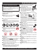
IMPORTANT HAND SIGNALS Figure 2 displays the basic hand signals commonly used in concrete pumping operations. Figure 2. Operation Hand Signals PAGE 14 — MAYCO LS300 CONCRETE PUMP • OPERATION AND PARTS MANUAL — REV.
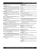
GENERAL INFORMATION CONCRETE MIX DESIGN Mix design is most important to achieve maximum pumpability. Pumpability is affected by, among other factors, the type and gradation of aggregate used. Natural aggregates make a more workable mix and pump more readily than crushed aggregates. A blend of natural and crushed aggregates will produce a workable mix. The type and gradation of aggregates is equally important for workability as the size and percentage of coarse aggregates in the mix.
GENERAL INFORMATION REGIONAL DIFFERENCES Concrete is made by mixing locally available rock and sand with cement and water. For this reason there are great differences in the pumpability of concrete from one region of the country to another. It is impossible to define a specific mix for each region that the concrete pump be will working in. Therefore, the mixes listed in Appendix - Concrete Mix Information will provide a basic guideline for establishing the proper mix design for your area.
HOW IT WORKS The following is a brief explanation of how the concrete cylinders, hydraulic cylinders, shuttle tube, valves and hopper work in sequence to pump concrete. The hydraulic pressure is generated by a variable volume, pressure compensated, axial piston pump that is driven by a diesel engine. The rod sides of the drive cylinders are hydraulically connected together creating a “slave circuit,” which allows hydraulic oil to transfer from one piston to the other.
PUMP COMPONENTS Figure 5. Major Pump Components PAGE 18 — MAYCO LS300 CONCRETE PUMP • OPERATION AND PARTS MANUAL — REV.
PUMP COMPONENTS Figure 5 illustrates the location of the major components for the LS300 Concrete Pump. The function of each component is described below: 1. Tow Hitch Coupler – Requires a 2-inch ball hitch or a 3-inch pintle. Capable of towing 6,000 lbs. 2. Documentation Box – Contains engine and pump operation, parts and maintenance information. 3. Manifold Access Door– Release latch and lift door to access the Hydraulic Manifold Block. 4.
DIGITAL CONTROL PANEL COMPONENTS Figure 6. Pump Digital Control Panel Components 1. 2. 3. 4. 5. 6. 7. Emergency Stop Button – Press emergency stop button to stop pump in an emergency. Turn knob counterclockwise to disengage the stop button. Ignition Switch – Insert the ignition key here to start the engine. Turn the key clockwise to the ON position, then continue turning clockwise to the START position and release. To stop the engine turn the key fully counterclockwise to the STOP position.
DIGITAL READOUT SCREEN PRIMARY SCREEN Screen 1 Indicates the various modes of the switch settings. Monitors engine RPM - Idle speed 900, High speed 2550. Battery charge indicator - Normal charge 13+ volts. Indicates electrical malfunction - Refer to Troubleshooting section. Screen 5 Displays the ON/OFF electrical signal status of the various 12 volt solenoids (Swing A circuit, Main A circuit, Main B circuit).
ENGINE COMPONENTS Figure 7. Deutz TD2009L04 Diesel Engine Components INITIAL SERVICING The engine (Figure 7) must be checked for proper lubrication and filled with fuel prior to operation. Refer to the manufacturer's engine manual for instructions and details of operation and servicing. 1. Fuel Filter – Service the fuel filter as recommended in the maintenance section of this manual. 2. Oil Filter – Prevents dirt and other debris from entering the engine.
INSPECTION CAUTION - GENERAL SAFETY GUIDELINES FUEL CHECK 1. NEVER operate the pump in a confined area or enclosed area structure that does not provide ample free flow of air. Check the fuel gauge built into the fuel tank cap (Figure 8) to determine if the pump's engine fuel is low. Refuel as needed. WARNING - EXPLOSIVE FUEL Diesel fuel is extremely flammable, and its vapors can cause an explosion if ignited. DO NOT start the engine near spilled fuel or combustible fluids.
INSPECTION ENGINE OIL CHECK 1. Remove the engine oil dipstick from its holder (Figure 10). 6. The oil listed in Table 4 is recommended to ensure better engine performance. Use class CD or higher grade motor oil. Figure 10. Engine Oil Dipstick 2. Make sure pump/engine is placed on level ground. HYDRAULIC OIL CHECK 3. Pull the engine oil dipstick (Figure 11) from its holder. 1. Determine if the hydraulic oil level is low by observing the level of the oil in the Hydraulic Oil Sight Glass (Figure 12).
INSPECTION 2. If the hydraulic oil level is low, remove the cap just above the oil level sight glass (Figure 13) and add the correct amount of hydraulic oil to bring the hydraulic oil level to a normal safe operating level. (Use Shell oil Tellus 68 or Mobil oil DFE26). Figure 13. Hydraulic Oil Filler Hole 3. Check the oil level in the lubrication box. If low, fill with up to 3 gallons of SAE #30 motor oil (Figure 14). The oil level must be checked daily.
SET-UP LOCATION OF PUMP 1. Place the pump in the best location on the site to pump concrete efficiently. 2. Lay down the hose in the shortest distance possible. REAR STABILIZER JACKS To reduce excessive vibration and rocking of the pump, set the rear stabilizers as follows: 1. Locate both the left and right rear stabilizer jacks (Figure 15). Figure 17. Rear Stabilizer Stand Deployment WARNING - REAR STABILIZER SAFETY NEVER place feet under jack while operating.
START-UP PROCEDURE 4. Place the Direction Control Switch to the FORWARD position (Figure 22). STARTING PROCEDURE WARNING - GENERAL SAFETY GUIDELINES DO NOT attempt to operate this concrete pump until the Safety, General Information and Inspection sections have been read and understood. REVERSE Figure 22. Direction Control Switch (FORWARD) 5. To start the engine, insert the key (Figure 23) into the ignition switch and turn the key to the ON position. e nc y S erg to p Em 1.
OPERATION HOSE LUBRICATION Before pumping, it is necessary to lubricate the hose. PUMPING WARNING - SAFETY GLASSES This procedure prevents separation and blockages in the hose. Inspect the lines at all times to prevent problems. Safety glasses MUST be worn at all times when operating the pump. Failure to follow safety guidelines can result in serious injury.
OPERATION 3. Scroll through the Digital Readout Screen with the scroll switch to go to Screen 7 (Figure 28). This screen will show the volume in strokes per minute. THROTTLE ON 7 STROKES: 100 STROKES/MIN 10.0 YDS/HR 0.0 Figure 28. Strokes Per Minute Display 4. Let the pump cycle until the hydraulic oil temperature (Figure 29) is approximately 50° to 60° F.
OPERATION REMOTE CONTROL (OPTIONAL) 4. Reinstall the control panel and tighten the 2 screws. The LS300 Concrete Pump has a remote control feature that allows the pump to be remotely controlled. If desired, the pump can be operated via a receiver/transmitter (radio) or a hardwire method, which utilizes a 25-ft. extension cable. Contact MQ Sales Department to order remote control. 5.
OPERATION Radio Remote Control Programming Before starting operation of the Radio Remote Control, go to Screen 9 of the Digital Readout Screen: RADIO ADDRESS 9 NO RADIO PRESS RESET TO LEARN A NEW ONE The cable remote control (Figure 38) has the following controls. 1. Press the ON/OFF button on the radio (wireless) remote control to turn on the power. Hold down the RESET switch. The display will now show: RADIO ADDRESS 9 NOW SCANNING FOR NEW TRANSMITTER 2.
PUMPING INFORMATION REMIXTURES Remixtures that are designed into the concrete mix by the redi-mix company or an architectural engineering company. This section lists common admixtures and a brief explanation of their functions: A. Pozzolith 300 – or the equivalent acts as a water retarder and a lubricant. On a lean mix, long pushes, stiff mixes, and vertical pushes, Pozzolith 300R helps pumpability. B. MBVR – air entraining, acts as a lubricant. C. Calcium Chloride – commonly referred to as C.C.
PUMPING INFORMATION The use of 2 -1/2” I.D. hose in these extreme cases reduces line pressures or the addition of slight amounts of water to the mix, if permissible, will permit easier pumping. The use of certain pumping admixtures may help.
PUMPING INFORMATION Using this procedure will make it easier to pump through the clean hose. Note: Once the concrete has reached the end of the hose, do not apply any more water in this manner as this procedure is used for starting only. 6. Hose sizing is very important: We strongly recommend on harsh mixes, vertical pushes, stiff concrete, shotcrete, long pushes, that a 2 -1/2” line be used as far as possible.
PUMPING INFORMATION CLEARING SHUTTLE TUBE BLOCKAGE The shuttle tube is plugged if volume at the discharge end of the hose stops and the hydraulic oil pressure gauge reads 3100 PSI or more. To clear a plug in the shuttle tube, great care must be taken as a dangerous condition will exist from pressure build-up inside the shuttle tube. (With the shuttle valve, the concrete can be pumped in reverse.) Use the following procedures to clear the shuttle tubes.
MAINTENANCE (PUMP) TABLE 5. MAINTENANCE CHECK SCHEDULE Daily Engine Oil Hourly Weekly Monthly X X Engine Air Filter X Fuel Filter X Hydraulic Oil Level erational 6-Months OpH ours X Lubrication Box X Replace Hydraulic Oil 500 hrs. Clean Hydraulic Filters Axle Crank X 2100 hrs. X Grease Shuttle Tube Zerk Points X 2 h rs Check System Pressure X 40 hrs. Check Hardware for Tightness X 40 hrs.
MAINTENANCE (PUMP) 5. Add water to the hopper. Pump and flush clean the entire hopper, shuttle tube and discharge elbow with water. 6. Scoop out 12 inches of concrete from the inboard end of the delivery hose. “Cork screw” a 6" x 6" x 8" sponge into the end of the first hose section. Reconnect the hose to the discharge elbow. 7. Fill hopper with water. Pump until sponge and clean water come out the discharge end of the hose and line system. 8.
MAINTENANCE (PUMP) BATTERY MAINTENANCE CAUTION - BATTERY MAINTENANCE SAFETY Wear safety glasses or face mask , protective clothes, and rubber gloves when working with battery. Mishandling of the battery shortens the service life of the battery and adds to maintenance cost. When handling the battery do the following: Be careful not to let the battery electrolyte come in contact with your body or clothing.
MAINTENANCE (PUMP) CYLINDER LUBRICATION BOX WARNING - FREEZING CONDITIONS When using the pump during freezing conditions, completely drain the water box and cover the hopper after pumping. Frozen liquid will restrict the piston travel and cause severe damage to the pump. CAUTION - SAFETY GUIDELINES Before checking lubrication level, stop the engine and remove the engine starter key. 1.
MAINTENANCE (PUMP) WEAR PLATE AND CUTTING RING Due to the abrasive nature of concrete, it is normal for the cutting ring to wear on its sides as it shears through the concrete inside the hopper. The metal-to-metal friction and the abrasiveness of the concrete will cause extreme wear and reduce sealing capability between the cutting ring and wear plate. If the two components do not properly seat against each other, slurry will pump into the hopper rather than out the discharge line. See Figure A.
MAINTENANCE (PUMP) CHANGING THE CONCRETE CYLINDER PISTON CUPS 6. The Rubber piston cups will occasionally require replacement depending on the following factors. Remove the three 3/8 – 16 x 3” bolts from the piston. Remove the front faceplate. 7. Install two the 3/8’ 16x3” bolts back into the piston – do not tighten. Use the two bolts as leverage to remove the rubber piston cup and rear components. 8.
MAINTENANCE (PUMP) CHANGING THE WEAR PLATE AND RING Wear Plate Installation Due to the swinging motion of the Nun-plate and the abrasive nature of concrete, it is normal for the cutting ring to wear on the side that shears through the concrete inside the hopper. If the wear ring and wear plate do not fully seat against each other the concrete slurry will pump into the hopper. This condition can be easily observed by the sudden change of the level of concrete inside the hopper during each stroke. 1.
MAINTENANCE (PUMP) WHEEL BEARINGS PRESSURE TEST After every 6 months of operation inspect the wheel bearings. Once a year, or when required, disassemble the wheel hubs remove the old grease and repack the bearings forcing grease between rollers, cone and cage with a good grade of high speed wheel bearing greases (never use grease heavier than 265 A.S.T.M. penetration “No. 2.”). 1. To determine the pressure of the Hydraulic System, set the Cylinder Stroke Control Switch (Figure 42) to the JOG position.
MAINTENANCE (TRAILER) The following trailer maintenance guidelines are intended to assist the operator in preventive maintenance. Trailer Brakes Properly functioning brake shoes and drums are essential to ensure safety. The brakes should be inspected the first 200 miles of operation. This will allow the brake shoes and drums to seat properly. After the first 200 mile interval, inspect the brakes every 3,000 miles. If driving over rough terrain, inspect the brakes more frequently.
MAINTENANCE (TRAILER) Periodically check the actuator mounting fasteners for damage or loosening. Inspect the actuator for worn or damaged parts. As you are towing your trailer, be aware of any changes in braking quality. This could be an early warning of brake or actuator malfunction and requires immediate attention. Consult a certified brake specialist to make necessary adjustment or repairs.
MAINTENANCE (TRAILER) Danger - Raising the Trailer NEVER crawl under the trailer unless it is on firm and level ground and resting on properly placed and secured jack stands. The possibility exists of the trailer falling thus causing equipment damage and severe bodily harm even death! Torsion Suspension The mounting bracket (Figure 49) of the torsion suspension assembly is bolted directly to the trailer frame.
TRAILER SAFETY GUIDELINES TRAILER SAFETY INFORMATION ■ ALWAYS use lower gears for climbing and descending grades. Safety precautions should be followed at all times when operating this equipment. Failure to read, understand and follow the Operating Instructions could result in injury to yourself and others. Loss of control of the trailer or tow vehicle can result in death or serious injury. ■ DO NOT ride the brakes while descending grades, they may get so hot that they stop working.
TRAILER SAFETY GUIDELINES CAUTION - Local Towing Regulations Check with your county or state safety towing regulations department before towing your trailer. Driving Conditions When towing a trailer, you will have decreased acceleration, increased stopping distance, and increased turning radius (which means you must make wider turns to keep from hitting curbs, vehicles, and anything else that is on the inside corner).
TRAILER SAFETY GUIDELINES Reporting Safety Defects If you believe that your vehicle has a defect that could cause a crash or could cause injury or death, you should immediately inform the National Highway Traffic Safety Administration (NHTSA) in addition to notifying us. Trailer Towing Tips Driving a vehicle with a trailer in tow is vastly different from driving the same vehicle without a trailer in tow. Acceleration, maneuverability and braking are all diminished with a trailer in tow.
TRAILER SAFETY GUIDELINES Some drivers place their hands at the bottom of the steering wheel, and while the tow vehicle is in reverse, “think” of the hands as being on the top of the wheel. When the hands move to the right (counterclockwise, as you would do to turn the tow vehicle to the left when moving forward), the rear of the trailer moves to the right.
TRAILER SAFETY GUIDELINES Tow Vehicle The towing hitch attached to your tow vehicle must have a capacity equal to or greater than the load rating of the trailer you intend to tow. The hitch capacity must also be matched to the tow vehicle capacity. Your vehicle dealer can provide and install the proper hitch on your tow vehicle. Suspension System Sway bars, shock absorbers, heavy duty springs, heavy duty tires and other suspension components may be required to sufficiently tow the trailer and pump.
TRAILER SAFETY GUIDELINES Coupler Types The trailer is shipped from the factory with a 2-inch ball coupler. Ball Hitch Coupler A ball hitch coupler (Figure 52) connects to a ball that is located on or under the rear bumper of tow vehicle. This system of coupling a trailer to a tow vehicle is sometimes referred to as “bumper pull.” A ball hitch trailer may be fitted with a tongue jack that can raise and lower the coupler. The tongue jack is mounted to the A-frame (front, or tongue) part of the trailer.
TRAILER SAFETY GUIDELINES WARNING - Defective Hitch Ball A worn, cracked or corroded hitch ball can fail while towing, and may result in death or serious injury. 2-INCH TRAILER COUPLER TOW VEHICLE Before coupling trailer, inspect the hitch ball for wear, corrosion and cracks. Replace worn or damaged hitch ball. WARNING - Uncoupled Hitch Ball A loose hitchball nut can result in uncoupling, leading to death or serious injury. Be sure the hitch ball is tight to the hitch before coupling the trailer.
TRAILER SAFETY GUIDELINES Attaching Safety Chain TOW VEHICLE TRAILER TONGUE IMPORTANT! SAFETY CHAIN MASTER LINK Breakaway Brake System If the coupler or hitch fails, a properly connected and working breakaway brake system (Figure 55) will apply the hydraulic brakes on the trailer. The safety chains will keep the tow vehicle attached and as the brakes are applied at the trailer’s axles, the trailer/tow vehicle combination will come to a controlled stop.
TRAILER SAFETY GUIDELINES Connecting Trailer Lights Connect the trailer lights to the tow vehicle’s electrical system using the electric connectors at the front of the trailer (tongue). Refer to the wiring diagram shown in the trailer wiring diagram section of this manual. Before towing the trailer check for the following: Running lights (turn on tow vehicle headlights). Brake Lights (step on tow vehicle brake pedal). Backup Lights (place tow vehicle gear shift in reverse).
TRAILER SAFETY GUIDELINES Lug nuts are also prone to loosen after first being assembled. When driving a new trailer (or after wheels have been remounted), check to make sure they are tight after the first 10, 25 and 50 miles of driving and before each tow thereafter. Failure to perform this check can result in a wheel parting from the trailer and a crash, leading to death or serious injury.
TRAILER SAFETY GUIDELINES Step 1. Locate the statement, “The weight of cargo should never exceed XXX kg or XXX lbs.,” on your vehicle’s Tire and Loading Information placard (Figure 56). This figure equals the available amount of equipment load capacity. Step 2. Determine the weight of the equipment being loaded on the tow vehicle. That weight may not safely exceed the available equipment load capacity.
TRAILER SAFETY GUIDELINES P: The “P” indicates the tire is for passenger vehicles. Next number: This three-digit number gives the width in millimeters of the tire from sidewall edge to sidewall edge. In general, the larger the number, the wider the tire. Next number: This two-digit number, known as the aspect ratio, gives the tire’s ratio of height to width. Numbers of 70 or lower indicate a short sidewall for improved steering response and better overall handling on dry pavement.
TRAILER SAFETY GUIDELINES Reference Figure 58 for additional tire information for light trucks. Make sure your tire valves have valve caps. ALWAYS check tire pressure on tow vehicle and trailer before towing. Check tire pressure at least once a month. DO NOT overload tow vehicle. Check the tire information and loading placard for safe allowable tire loading conditions.
TRAILER SAFETY GUIDELINES WARNING - Flying Objects ALWAYS wear safety glasses when removing or installing force fitted parts DO NOT attempt to repair or modify a wheel. DO NOT install an inner-tube to correct a leak through the rim. If the rim is cracked, the air pressure in the inner tube may cause pieces of the rim to explode (break off) with great force and cause serious eye or bodily injury.
TRAILER SAFETY GUIDELINES Figure 60. Trailer to Tow Vehicle Wiring Diagram Lights and Signals Before each tow, check the trailer taillights, stoplights, turn signals and any clearance lights for proper operation. Replace any broken or burned-out lamps as necessary. Check the wire harness for cuts, fraying or other damage. If it needs replacing, contact your dealer. WARNING - Trailer Lights Improper operating taillights, stoplights and turn signals can cause collisions. Check all lights before each tow.
TROUBLESHOOTING (PUMP) The hydraulic troubleshooting procedures listed below are intended for use by individuals equipped with the proper tools and equipment and are familiar with hydraulic systems and safe shop practices. Use the Pump Troubleshooting Table (Table 8) to identify possible causes for the pump’s malfunction. Contact the Multiquip Service department for the proper repair procedure.
TROUBLESHOOTING (PUMP) TABLE 9.
TROUBLESHOOTING (ENGINE) Practically all breakdowns can be prevented by proper handling and maintenance inspections, but in the event of a breakdown, please take a remedial action following the diagnosis based on the Engine Troubleshooting (Table 10) information shown below and on the proceeding page. If the problem cannot be remedied, please leave the unit just as it is and consult our company's business office or service plant. TABLE 10.
TROUBLESHOOTING (TRAILER BRAKE SYSTEM) Practically all breakdowns can be prevented by proper handling and maintenance inspections, but in the event of a breakdown, please take a remedial action following the diagnosis based on the Brake System Troubleshooting (Table 10) information shown below and on the proceeding page. If the problem cannot be remedied, please leave the unit just as it is and consult our company's business office or service plant. TABLE 11.
TROUBLESHOOTING (ELECTRICAL) Refer to Figure 61 for the location of components for troubleshooting. TABLE 12. ELECTRICAL TROUBLESHOOTING MALFUNCTION READING (Screen 1) PROBABLE CAUSE SOLUTION Burnt 12 V cycling solenoid. Measure solenoid coil resistance. It should read 6 ohms. Replace valve. Wire connection broken. Replace broken wire. The 12-volt cycling solenoid is shor ted directly to ground. Measure solenoid coil resistance. It should read 6 ohms. Replace valve.
TROUBLESHOOTING (ELECTRICAL) TABLE 12. ELECTRICAL TROUBLESHOOTING (continued) MALFUNCTION READING (Screen 1) PROXIMITY SWITCH C PROXIMITY SWITCH D PROBABLE CAUSE SOLUTION Digital Control Box not sending signal. Check screen #5 for operational status. Shuttle cylinder shor t stroking not energizing proximity sensor. ■ Mis-aligned hopper ■ Discharge nipple seizing ■ Hopper outlet requires lubrication Digital Control Box not sending signal. Check screen #5 for operational status.
TROUBLESHOOTING (ELECTRICAL) MAIN “A” SOLENOID MAIN “B” SOLENOID PROXIMITY SWITCH “A” E PROXIMITY SWITCH “D” F P 1 B 1 T 1 1 2 A P T 2 PROXIMITY SWITCH “C” V-BELT SWING “B” SOLENOID PROXIMITY SWITCH “B” SWING “A” SOLENOID ALTERNATOR INTERNAL FUEL SOLENOID Figure 61. Location of Components for Electrical Troubleshooting PAGE 68 — MAYCO LS300 CONCRETE PUMP • OPERATION AND PARTS MANUAL — REV.
WIRING DIAGRAM (CONTROL BOX) TBD Figure 62. Connections to Digital Control Box - J1 and J2 Connectors ( 1 of 2) MAYCO LS300 CONCRETE PUMP • OPERATION AND PARTS MANUAL — REV.
WIRING DIAGRAM (CONTROL BOX) TBD Figure 62. Connections to Digital Control Box - J1 and J2 Connectors ( 2 of 2) PAGE 70 — MAYCO LS300 CONCRETE PUMP • OPERATION AND PARTS MANUAL — REV.
WIRING DIAGRAM (CONTROL BOX) TBD Figure 63. Connections to Digital Control Box - J3 and J4 Connectors ( 1 of 2) MAYCO LS300 CONCRETE PUMP • OPERATION AND PARTS MANUAL — REV.
WIRING DIAGRAM (CONTROL BOX) TBD Figure 63. Connections to Digital Control Box - J3 and J4 Connectors ( 2 of 2) PAGE 72 — MAYCO LS300 CONCRETE PUMP • OPERATION AND PARTS MANUAL — REV.
WIRING DIAGRAM (DIGITAL READOUT SCREEN) BROWN (DECREASE) GREEN (INCREASE) RED (IGNITION +12VDC) BLUE (UNLOADER SOLENOID) RED (FUEL SOLENOID) RED/BLACK J1 DIGITAL READOUT MODULE BLACK RED WHITE BLUE 4 5 YELLOW GREEN 6 +12VDC IN CONTROLLER BLACK POTTED BOX BROWN ORANGE 7 RED 8 1 2 3 4 RADIO REMOTE CONTROL CONNECTOR +12VDC OUT E-STOP 5 6 7 8 1 2 3 4 5 6 7 8 J3 BLACK J4 1 2 3 WHITE GND J2 BROWN BLACK PURPLE T0 J1-7 (RED) T0 J4-7 (BLK) RED 1 1 3 3 2 2 ORANGE NC 1 NC 1 NC 1 SCR
WIRING DIAGRAM (HOPPER VIBRATOR) Figure 65. Optional Hopper Vibrator Wiring Diagram PAGE 74 — MAYCO LS300 CONCRETE PUMP • OPERATION AND PARTS MANUAL — REV.
HYDRAULIC SYSTEM DIAGRAM Figure 66. Hydraulic System Diagram MAYCO LS300 CONCRETE PUMP • OPERATION AND PARTS MANUAL — REV.
MANIFOLD BLOCK PORTS MANIFOLD BLOCK PORTS A1 Connect to Hydraulic Cylinder A2 Connect to Shuttle Cylinder B1 Connect to Hydraulic Cylinder B2 Connect to Shuttle Cylinder P1 Connect to Flow Control Valve P2 Connect to Hydraulic Pump T1 Connect to Heat Exchanger T2 Connect to Hydraulic Tank 1 Connect to Accumulator Tank P ACC B 1 T 1 1 2 A P B2 T 2 A2 ACC P P1 1 B 1 T 1 P 1 2 A T T1 2 B1 A1 T2 P2 Figure 67.
APPENDIX — CONCRETE MIX INFORMATION The following information has been extracted from actual testing laboratory reports. The purpose of this printing is only to help create a better understanding of the importance of uniform gradation and proportioning of materials which affect pumpability of concrete mixes. These weights and proportions illustrate that when the sieve analysis is ideal, the sand/rock ratio can be adjusted (65% sand 35% rock) and pumpability should be excellent.
APPENDIX — CONCRETE MIX INFORMATION A.S.T.M. STANDARD SPECIFICATION FOR GRADING AGGREGATE PAGE 78 — MAYCO LS300 CONCRETE PUMP • OPERATION AND PARTS MANUAL — REV.
APPENDIX — SLUMP TEST PROCEDURE 1. To obtain a representative sample (concrete), take several samples at three or more regular intervals throughout the discharge of the mixer or truck. DO NOT take samples at the beginning or end of the discharge. 2. Dampen the inside of the cone and place it on a smooth, moist, nonabsorbent, level surface large enough to accommodate both the slumped concrete and the slump cone. Stand on the “foot pieces” throughout the test procedure to hold the cone firmly in place. 3.
APPENDIX — RECOMMENDED SHOTCRETE SYSTEM Figure 69. Recommended Shotcrete System PAGE 80 — MAYCO LS300 CONCRETE PUMP • OPERATION AND PARTS MANUAL — REV.
APPENDIX — RECOMMENDED SHOTCRETE SYSTEM RECOMMENDED SHOTCRETE SYSTEM NO. 1 PART NO. EM28906 PART NAME COUPLING, 5” H-D “CF” 2 EM25837 ELBOW, 5"x4”x90° 3 EM28905 COUPLING, 4” H-D w/GASKET & PIN 4 EM402552 REDUCER, 4”x2.5”x53” H-D ENDS 5 EM28061 PIPE, 2.5”x120w x 10’ H-D 6 EM289035 COUPLING, 2.5” H-D w/GASKET & PIN 7 EM28001DD REDUCER, 2.5”x2”x36” H-D 8 EM23815D REDUCER, 2.5”x2” w/AIR VIBRATOR 9 EM28902 COUPLING, 2” H-D w/GASKET & PIN 10 EM23101 AIR VIBRATOR ASSY.
APPENDIX — RECOMMENDED SHOTCRETE ACCESSORIES RECOMMENDED SHOTCRETE ACCESSORIES Figure 70. Shotcrete System Accessories Use a 1-3/8" rubber nozzle tip for a wide spray pattern. Use a 1-1/4" rubber nozzle tip for a narrow spray pattern. DO NOT INSTALL THE NOZZLE AT THE END OF THE HOSE UNTIL THE FIRST MATERIAL HAS PASSED THROUGH THE ENTIRE HOSE LENGTH. Disassemble and clean the nozzle assembly thoroughly after each job. Grease all threads before reassembly.
APPENDIX — RECOMMENDED SHOTCRETE ACCESSORIES RECOMMENDED SHOTCRETE ACCESSORIES NO. 1 2 3 4 5 6 7 8 9 10 11 11 12 * 13 * 14 * 15 * 16 * 17 * 18 * 19 * 20 21 PART NO. EM26107 EM23101 EM132 EM23407 EM23408 EM23411 EM912073 EM23409 EM923346 EM406 EM24841 EM24844 EM23802 EM23803 EM20816 EM23804 EM23805 EM23806 EM23807 EM911076 EM23808 PART NAME QTY. REMARKS HOPPER SCREEN ......................... 1 ..........
EXPLANATION OF CODE IN REMARKS COLUMN The following section explains the different symbols and remarks used in the Parts section of this manual. Use the help numbers found on the back page of the manual if there are any questions. NOTICE The contents and part numbers listed in the parts section are subject to change without notice. Multiquip does not guarantee the availability of the parts listed. SAMPLE PARTS LIST NO. 1 2% 2% 3 4 PART NO. PART NAME QTY. REMARKS 12345 BOLT......................1 .....
SUGGESTED SPARE PARTS LS300 CONCRETE PUMP 1 Unit Qty. P/N 1 .......... EM16462 .............. 4 .......... EM98050 .............. 4 .......... EM16493 .............. 1 .......... EM98033 .............. 2 .......... EM14408 .............. 2 .......... EM16145 .............. 1 .......... EM98021 .............. 2 .......... EM16816-1A ........ 1 .......... EM16816-2 ........... 2 .......... EM98065 .............. 1 .......... EM98022 .............. 1 .......... EM98065 .............. 2 .......... EM14407 .....
NAMEPLATE AND DECALS PAGE 86 — MAYCO LS300 CONCRETE PUMP • OPERATION AND PARTS MANUAL — REV.
NAMEPLATE AND DECALS NO. 1 2 3 4 5 6 7 8 9 10 11 12 13 PART NO. DCL301 35137 EM97070 DCL300 EM97084 49002 EM511091 EM97072 EM98000 511709 TBD EM516936 517907 PART NAME DECAL, SHUTTLE TUBE DANGER DECAL, CAUTION READ MANUAL DECAL, PUMPING PRESSURE DECAL DECAL, DANGER LUBRICATION BOX DECAL, MAINTENANCE DECAL, WARNING COUPLER DECAL, MINIMUM OIL LEVEL DECAL, CAUTION - OP. INSTRUCTIONS DECAL, CAUTION - GREASE 2 HOURS DECAL, 800-30-MAYCO DECAL, VIN IDENTIFICATION DECAL, LS300 DIGITAL CONTROL PANEL LOGO QTY.
NAMEPLATE AND DECALS PAGE 88 — MAYCO LS300 CONCRETE PUMP • OPERATION AND PARTS MANUAL — REV.
NAMEPLATE AND DECALS NO. 1 2 3 4 5 6 7 8 9 PART NO. DCL301 EM995 DCL304 EM955 DCL302 EM696 EM985 EM516937 PART NAME QTY. REMARKS DECAL, SHUTTLE TUBE DANGER 1 DECAL, CAUTION DIESEL FUEL 1 DECAL, DANGER IMPROPER CHARGING 1 DECAL, DANGER CHARGING ACCUM. 1 DECAL, WARNING BURN HAZARD 1 DECAL, CAUTION - TOWING DECAL 1 SERIAL PLATE ...................................................... 1 .......... CONTACT MQ PARTS DEPT.
FRAME ASSY. PAGE 90 — MAYCO LS300 CONCRETE PUMP • OPERATION AND PARTS MANUAL — REV.
FRAME ASSY. NO. 1 2 3 4 5 6 7 10 11 12 13 14 15 PART NO. 516758 516581 EM25610 EM744 EM491686 EM963055 0166 A 518025 518026 504456 6109180 EM70186 EM491744 PART NAME FRAME, MAIN CHAIN, TRAILER HITCH JACK STAND, FRONT CLEVIS PIN PIN HHB 3/8 NC X 3/4 G5 WASHER, LOCK 3/8" MED FENDER, BOLT ON, RIGHT FENDER, BOLT ON, LEFT BOLT 1/2"NC X 3/4" G5 WASHER, LOCK 1/2" STABILIZER STAND RIVET, POP AM-44 QTY. 1 2 1 2 2 5 5 1 1 10 10 2 2 REMARKS MAYCO LS300 CONCRETE PUMP • OPERATION AND PARTS MANUAL — REV.
AXLE ASSY. PAGE 92 — MAYCO LS300 CONCRETE PUMP • OPERATION AND PARTS MANUAL — REV.
AXLE ASSY. AXLE ASSY. (RIGHT/LEFT) NO. PART NO. PART NAME QTY. REMARKS 1 516931 AXLE, TORSION BAR ASSY. 1 2 EM092305 BRAKE ASSY COMPLETE, RIGHT ................ 1.............. INCLUDES ITEMS W/# 2 EM092306 BRAKE ASSY COMPLETE, LEFT .................. 1.............. INCLUDES ITEMS W/% .......................................................................................... SEE NOTE BELOW 3 363198 OIL SEAL 1 4 363196 INNER BEARING CONE 2 IN. 1 5 383911 INNER BEARING CUP 2 IN.
BRAKE LINE ASSY. PAGE 94 — MAYCO LS300 CONCRETE PUMP • OPERATION AND PARTS MANUAL — REV.
BRAKE LINE ASSY. NO. 1 2 3 4 PART NO. 34566 EM512877 EM512876 34565 PART NAME KIT, MAIN BRAKE LINE ADAPTOR, STRAIGHT ADAPTOR, ELBOW KIT, WHEEL BRAKE LINE QTY. 1 2 2 1 REMARKS MAYCO LS300 CONCRETE PUMP • OPERATION AND PARTS MANUAL — REV.
BRAKE LIGHT ASSY. PAGE 96 — MAYCO LS300 CONCRETE PUMP • OPERATION AND PARTS MANUAL — REV.
BRAKE LIGHT ASSY. NO. 1 2 PART NO. 26536 515419 PART NAME BRAKE LIGHT ASSY. HARNESS ASSY. W/RECEPTACLES QTY. 2 1 REMARKS MAYCO LS300 CONCRETE PUMP • OPERATION AND PARTS MANUAL — REV.
TRAILER HITCH ASSY. PAGE 98 — MAYCO LS300 CONCRETE PUMP • OPERATION AND PARTS MANUAL — REV.
TRAILER HITCH ASSY. NO. 1 2 3 4 5 6 7 8 PART NO. EM29228 EM19067 EM503111 EM492600 EM492584 EM507658 EM492586 16137 PART NAME QTY. COUPLING, TRAILER 2 IN.BALL, 6000 LBS 1 ACTUATOR, BRAKE 1 BOLT, HEX HEAD 1/2 NC X 4-1/2 IN. 3 WASHER, FLAT 1/2 IN. 3 3 NUT, LOCK 1/2 IN. BOLT, HEX HEAD 5/8 NC X 4-1/2 IN. G5 2 NUT, LOCK 5/8 IN. 2 TOW RING, 3 IN. LUNETTE EYE 1 REMARKS MAYCO LS300 CONCRETE PUMP • OPERATION AND PARTS MANUAL — REV.
BATTERY ASSY. PAGE 100 — MAYCO LS300 CONCRETE PUMP • OPERATION AND PARTS MANUAL — REV.
BATTERY ASSY. NO. 1 2 3 4 PART NO. 10318 491344 515177 515133 PART NAME BATTERY BOX W/ BELT BATTERY 12V BATTERY CABLE POSITIVE BATTERY CABLE NEGATIVE QTY. 1 1 1 1 REMARKS MAYCO LS300 CONCRETE PUMP • OPERATION AND PARTS MANUAL — REV.
HOPPER ASSY. PAGE 102 — MAYCO LS300 CONCRETE PUMP • OPERATION AND PARTS MANUAL — REV.
HOPPER ASSY. NO. 1 2 3 4 5 6 7 8 PART NO. EM517753 EM16184 EM70860-1 EM50417 EM508830 492378 0166 A EM70860 PART NAME HOPPER ASSY HOPPER SEAL PISTON CUP HOLDER PISTON CUP SEAL HANDLE BOLT 3/8 X 1-3/4 IN. WASHER, LOCK 3/8 IN. HANDLE ASSY. QTY. 1 1 1 1 1 4 4 1 REMARKS MAYCO LS300 CONCRETE PUMP • OPERATION AND PARTS MANUAL — REV.
HOPPER ATTACHMENT ASSY. PAGE 104 — MAYCO LS300 CONCRETE PUMP • OPERATION AND PARTS MANUAL — REV.
HOPPER ATTACHMENT ASSY. HOPPER ATTACHMENT ASSY. NO. 1 2 3 4 5 6 7 8 9 10 11 12 13 14 15 16 17 18 19 20 PART NO. EM514204 EM514620 EM491686 EM70134-2 EM505723 EM16166 505728 EM14165 EM619 EM968446 505121 EM968446 505123 492491 6109160 492379 3019092 515395 492584 EM969013 PART NAME SPLASH PLATE HINGE PIN COTTER PIN 1/8 X 1-1/2 IN. PIN, SPLASH PLATE COTTER PIN 5/32 X 1-1/2 IN. TIE ROD NUT, HEX 1 IN. NC EYE BOLT 3/4 IN. O-RING 3/4 IN. NUT, HEX 3/4 IN. BOLT 3/4 IN. X 3 IN. HEX NUT 3/4 IN.
HOPPER INTERIOR ASSY. PAGE 106 — MAYCO LS300 CONCRETE PUMP • OPERATION AND PARTS MANUAL — REV.
HOPPER INTERIOR ASSY. HOPPER INTERIOR ASSY. NO. 1 2 3 4 5 6 6A 7 8 9 10 11 12 13 14 15 17 18 19 20 21 25 26 27 28 29 30 31 32 PART NO. EM16145A EM284 EM16175 EM16170 EM16176 EM98022 EM16816-1A EM16816-2 EM16804A EM104 EM923348 EM25803 EM98065 EM512212 491701 EM210 EM16811 EM25843 EM104 491719 EM923348 EM514357 EM98021 EM969023 EM265 EM923350 EM151 EM264 EM517700 PART NAME QTY. SWING AXLE BUSHING 2 STUD 1 IN.
SHUTTLE CYLINDER ASSY. PAGE 108 — MAYCO LS300 CONCRETE PUMP • OPERATION AND PARTS MANUAL — REV.
SHUTTLE CYLINDER ASSY. NO. 1 2 3 4 5 6 7 7A 8 9 9A 10 * 11 12 13 14 15 * 16 * 18 * 19 * 20 21 22 23 24 25 26 27 28 29 * PART NO. EM16145A EM510684 EM16169 EM510514 EM505490 EM16814 EM509221 EM491690 EM417 EM98205 EM98106SK EM254549 492397 EM621 6109180 492584 0820270000 0820270000 515249 0509440000 3322 EM518013 EM518012 516965 0202 EM923023 2105164 518016 TBD 518044 PART NAME QTY.
LUBRICATION PISTONS ASSY. PAGE 110 — MAYCO LS300 CONCRETE PUMP • OPERATION AND PARTS MANUAL — REV.
LUBRICATION PISTONS ASSY. NO. 1 2 3 4 5 6 7 8 9 10 11 12 13 14 16 17 18 19 20 21 22 23 24 25 26 27 28 29 30 31 32 33 PART NO. EM510265 EM16464 EM16465 EM98050 EM14408 EM16493 EM16462 EM16461 EM14407 EM80801 EM25110 EM963610 0166 A 3019092 EM514197 EM507895 EM515796 EM514610 491754 492378 0166 A EM274351 EM50425 492451 EM50443 514208 EM98163 EM98135 EM98134 EM98138 514611 504505 PART NAME QTY. BOLT, HEX HEAD 3/8 NC X 3-1/2 IN.
LUBRICATION PISTONS ASSY. PAGE 112 — MAYCO LS300 CONCRETE PUMP • OPERATION AND PARTS MANUAL — REV.
LUBRICATION PISTONS ASSY. LUBRICATION PISTONS ASSY. NO. PART NO. PART NAME QTY. 34 492364 BOLT, HEX HEAD 5/16 NC X 1 IN. G5 6 35 EM492623 WASHER, LOCK 5/16 IN. 4 36 EM514216 ADJUSTMENT ROD, PROXIMITY SWITCH 2 37 EM492556 NUT, HEX 1/2 IN. 4 38 EM514207 BRACKET, ADJUSTMENT ROD 2 39 EM492597 WASHER, FLAT 5/16 IN. 6 40 EM492582 NUT, HEX HEAD 5/16 IN 2 41 EM80423A CYLINDER, MAIN 2 42 518001 HOSE, MAIN HYD. CYLINDER 2 43 EM514202 EXTENSION, SPACER 2 6 44 EM185 BOLT, SOCKET HEAD 3/8 NC X 3 IN.
FUEL TANK/WATER SEPARATOR ASSY. PAGE 114 — MAYCO LS300 CONCRETE PUMP • OPERATION AND PARTS MANUAL — REV.
FUEL TANK/WATER SEPARATOR ASSY. NO. 1 2 3 4 5 6 7 8 9 10 11 12 13 14 15 16 17 18 19 20 21 PART NO. EM516869 516880 492362 EM923343 2108 EM514559 506208 EM514536 EM20426 EM514536 EM20763 509369 491237 506094 492356 2101402 EM923057 516878 EM20426 518067 TBD PART NAME COVER, DIESEL TANK GASKET BOLT 5/16 X 5/8 IN. WASHER, LOCK 5/16 IN. CAP, FUEL ADAPTOR CLAMP HOSE, FUEL RETURN 5/16 IN. ADAPTER HOSE, FUEL FILTER 5/16 IN.
HEAT EXCHANGER ASSY. PAGE 116 — MAYCO LS300 CONCRETE PUMP • OPERATION AND PARTS MANUAL — REV.
HEAT EXCHANGER ASSY. NO. 1 2 3 4 5 6 7 8 9 10 11 12 PART NO. EM98118 EM516812 EM963610 EM923343 EM923023 0202 2105164 EM25497 518001 EM25497 518000 EM98264 PART NAME HEAT EXCHANGER COVER, HEAT EXCHANGER BOLT 5/16 IN. X 3/4 IN. WASHER, LOCK 5/16 IN. WASHER, FLAT 5/16 IN. BOLT 5/16 X 1 IN. NUT 5/16 IN. FITTING, 90° HOSE 4000 PSI FITTING, 90° HOSE 4000 PSI MOTOR AND FAN ASSY QTY. 1 1 4 6 8 2 4 1 1 1 1 1 REMARKS MAYCO LS300 CONCRETE PUMP • OPERATION AND PARTS MANUAL — REV.
ACCUMULATOR ASSY. 1 2 3 AC C 4 6 TEST/ CHARGE KIT PAGE 118 — MAYCO LS300 CONCRETE PUMP • OPERATION AND PARTS MANUAL — REV.
ACCUMULATOR ASSY. NO. 1 2 3 4 6 PART NO. EM513126 EM98265 TBD TBD EM98052 PART NAME CLAMP ACCUMULATOR, 1 PINT FITTING, STRAIGHT 3/8" HOSE TEST/CHARGE KIT, ACCUMULATOR QTY. 1 1 1 1 1 REMARKS MAYCO LS300 CONCRETE PUMP • OPERATION AND PARTS MANUAL — REV.
LUBRICATION PANEL ASSY. Grease daily, two or three shots of #2 multipurpose automotive grease. Over greasing any bearing will not damage the machine. ALWAYS grease before and after pump operation. POSITION LOCATION LENGTH OF LINES A ................................................. CLEVIS GREASE POINT ................................................ 34 in. (1.1 m) B ................................................. SWING AXLE BUSHING GREASE POINT ...................... 26 in. (.85 m) C.....................
LUBRICATION PANEL ASSY. NO. 1 2 3 4 PART NO. EM491701 EM508812 EM510684 EM505516 PART NAME GREASE FITTING CONNECTOR CONNECTOR HOSE, PLASTIC QTY. 3 2 1 A/R REMARKS MAYCO LS300 CONCRETE PUMP • OPERATION AND PARTS MANUAL — REV.
ENGINE COVER ASSY. PAGE 122 — MAYCO LS300 CONCRETE PUMP • OPERATION AND PARTS MANUAL — REV.
ENGINE COVER ASSY. NO. 1 2 3 4 5 6 7 8 PART NO. EM516904 492356 2101402 EM923057 492363 EM516910 2105164 TK6737260 PART NAME COVER, TOP BOLT 1/4" NC X 3/4" G5 WASHER, SPRING 1/4 IN. WASHER 1/4 IN. BOLT, 5/16" NC 3/4" G5 COVER, FRONT ENGINE NUT 5/16" DOCUMENT BOX QTY. 1 19 19 19 2 1 2 1 REMARKS MAYCO LS300 CONCRETE PUMP • OPERATION AND PARTS MANUAL — REV.
HYDRAULIC TANK ASSY. PAGE 124 — MAYCO LS300 CONCRETE PUMP • OPERATION AND PARTS MANUAL — REV.
HYDRAULIC TANK ASSY. NO. 1 2 3 4 5 6 7 8 9 10 11 12 13 14 15 16 17 18 19 20 21 22 PART NO. 516756 517295 516870 516879 492362 EM923343 EM98263 492267 516917 518010 518014 518190 518191 518005 518011 518189 EM98245 TBD EM97067 EM25523 518008 EM98188 PART NAME HYDRAULIC/FUEL TANK LATCH TANK COVER PLATE RESERVOIR GASKET NUT, 5/16" X 5/8" WASHER, LOCK 5/16’ CAP ASSY.
ENGINE ASSY. 15 20 PART OF ENGINE COVER 16 17 12 10 11 13 1 13 14 21 22 23 2 7 5 8 4 6 3 9 PAGE 126 — MAYCO LS300 CONCRETE PUMP • OPERATION AND PARTS MANUAL — REV.
ENGINE ASSY. NO. 1 2 3 4 5 6 7 8 9 10 11 12 13 14 15 16$ 17$ 20 21 22 23 PART NO. EM98241 TBD 518021 518022 TBD TBD EM963692 6109180 6109160 EM492263 0166 A 517777 TBD EM517549 04112427 04115210 EM517552 EM510731 1456 4114220 2931095 PART NAME QTY.
THROTTLE ASSY. PAGE 128 — MAYCO LS300 CONCRETE PUMP • OPERATION AND PARTS MANUAL — REV.
THROTTLE ASSY. NO. 1 2 3 PART NO. 517795 EM517548 517796 PART NAME THROTTLE LEVER ROD HAND CONTROL BRACKET, THROTTLE QTY. 1 1 1 REMARKS MAYCO LS300 CONCRETE PUMP • OPERATION AND PARTS MANUAL — REV.
HYDRAULIC PUMP ASSY. PAGE 130 — MAYCO LS300 CONCRETE PUMP • OPERATION AND PARTS MANUAL — REV.
HYDRAULIC PUMP ASSY. NO. 1 2 3 4 5 6 7 8 9 10 11 12 13 14 15 16 19 20 21 22 23 PART NO.
MANIFOLD ASSY. 1 P 1 B E F 1 T 2 P 1 A 2 T 2 1 1 1 P P B B 1 1 1 T A 1 1 T P 1 2 A 9 P 2 T 2 2 16 T 3 17 6 17 17 17 4 16 4 10 6 1 P 1 B T 1 11 P B2 2 1 A AC C T 15 A2 2 12 15 13 14 PAGE 132 — MAYCO LS300 CONCRETE PUMP • OPERATION AND PARTS MANUAL — REV.
MANIFOLD ASSY. NO. 1 2 3 4% 6 7 9 10 11 12 13 14 15 16 17 PART NO. TBD TBD EM98243 EM98221 EM98222 TBD TBD TBD CVH161P65 EM98226 TBD CVH081P 512201 516916 EM491372 PART NAME QTY. REMARKS BOLT 4 WASHER, LOCK 4 MANIFOLD ASSY. ................................................1 ...........
CONTROL BOX ASSY. 20 21 12 8A 8 5 13 14 15 6 18 4 3 1 7 2 PAGE 134 — MAYCO LS300 CONCRETE PUMP • OPERATION AND PARTS MANUAL — REV.
CONTROL BOX ASSY. CONTROL BOX ASSY. NO. 1 2 3 4 5 6 7 8 8A 12 13 14 15 18 20 21 PART NO. EM517648 0202 EM923023 2105164 TBD EM98206 EM98206K EM517177 EM517186 EM98120 EM98119 EM98121 EM98122 EM97068 EM98122 EM98122 PART NAME QTY. CONTROL BOX ASSY 1 BOLT 5/16 X 1 IN. 4 WASHER, FLAT 5/16 IN. 4 NUT 5/16 IN. 4 OVERLAY, CONTROL PANEL 1 IGNITION SWITCH ASSY. 1 KEY, IGNITION 1 EMERGENCY STOP SWITCH ASSY. 1 CONTACT BLOCKS, EMERGENCY SWITCH 3 FLOW DIRECTION SWITCH ASSY. 1 MAIN CONTROL SWITCH ASSY.
CONTROL BOX HARNESS ASSY. PAGE 136 — MAYCO LS300 CONCRETE PUMP • OPERATION AND PARTS MANUAL — REV.
CONTROL BOX HARNESS ASSY. NO. 1 2 3 4 5 6 7 8 PART NO. EM517992 344102000 EM517993 EM517994 EM518023 EM518024 509588 16716 PART NAME WIRE HARNESS 1 FUSE, 30 AMP WIRE HARNESS 2 WIRE HARNESS 3 WIRE HARNESS 4 WIRE HARNESS 5 POLY FLEX TUBE 1/2 IN. BLACK CONDUCTIVE DIVIDER 3/8 IN. QTY. 1 1 1 1 1 1 AR AR REMARKS MAYCO LS300 CONCRETE PUMP • OPERATION AND PARTS MANUAL — REV.
TERMS AND CONDITIONS OF SALE — PARTS PAYMENT TERMS 5. Parts must be in new and resalable condition, in the original Multiquip package (if any), and with Multiquip part numbers clearly marked. 6. The following items are not returnable: Multiquip reserves the right to quote and sell direct to Government agencies, and to Original Equipment Manufacturer accounts who use our products as integral parts of their own products. a. SPECIAL EXPEDITING SERVICE Terms of payment for parts are net 30 days.
MAYCO PUMP WARRANTY MECHANICAL DRIVE MODELS HYDRAULIC DRIVE MODELS MAYCO PUMP, hereinafter referred to as “Manufacturer’, warrants each new Mayco Pump sold by the manufacturer to be free from defects in material and workmanship, under normal use and service, for a period of one year after the date of delivery to the original retail purchaser.
OPERATION AND PARTS MANUAL HERE’S HOW TO GET HELP PLEASE HAVE THE MODEL AND SERIAL NUMBER ON-HAND WHEN CALLING UNITED STATES Multiquip Corporate Office 18910 Wilmington Ave. Carson, CA 90746 Contact: mq@multiquip.com MQ Parts Department Tel. (800) 421-1244 Fax (800) 537-3927 Mayco Parts 800-427-1244 310-537-3700 Fax: 800-672-7877 Fax: 310-637-3284 Warranty Department 800-306-2926 310-537-3700 Fax: 800-672-7877 Fax: 310-637-3284 Service Department 800-421-1244, Ext. 279 310-537-3700, Ext.