OPERATION AND PARTS MANUAL SERIES MODEL C30HDZ BALL VALVE CONCRETE PUMP (DEUTZ F2L1011F DIESEL ENGINE) Revision #12 (04/03/12) To find the latest revision of this publication, visit our website at: www.multiquip.com THIS MANUAL MUST ACCOMPANY THE EQUIPMENT AT ALL TIMES.
PROPOSITION 65 WARNING Diesel engine exhaust and some of PAGE 2 — MAYCO C30HDZ PUMP — OPERATION AND PARTS MANUAL — REV.
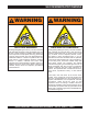
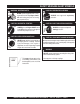
SILICOSIS/RESPIRATORY WARNING WARNING WARNING SILICOSIS WARNING RESPIRATORY HAZARDS Grinding/cutting/drilling of masonry, concrete, metal and other materials with silica in their composition may give off dust or mists containing crystalline silica. Silica is a basic component of sand, quartz, brick clay, granite and numerous other minerals and rocks. Repeated and/or substantial inhalation of airborne crystalline silica can cause serious or fatal respiratory diseases, including silicosis.
TABLE OF CONTENTS MAYCO C30HDZ CONCRETE PUMP COMPONENT DRAWINGS Nameplate and Decals....................................... 62-63 Compensator Piston Rod Assembly .................. 64-65 Connecting Rod - Drive Side Assembly ............. 66-67 Rocker Assembly ............................................... 68-69 Countershaft Assembly ...................................... 70-71 Crankshaft Assembly ......................................... 72-73 Manifold Assembly ............................................
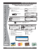
www.multiquip.com PARTS ORDERING PROCEDURES Ordering parts has never been easier! Choose from three easy options: Order via Internet (Dealers Only): Best Deal! Effective: January 1st, 2006 If you have an MQ Account, to obtain a Username and Password, E-mail us at: parts@multiquip. com. Order parts on-line using Multiquip’s SmartEquip website! N View Parts Diagrams N Order Parts N Print Specification Information To obtain an MQ Account, contact your District Sales Manager for more information.
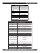
PUMP SPECIFICATIONS Table 1. C-30HDZ Pump Specifications Pump Type Reciprocating Piston Pumping Rate Up to 25 cu. yds. per hour* Vertical Pumping Height Up to 150 ft. (45.73 m) Horizontal Pumping Distance 400 - 500 ft. (122 - 152 m)* Max. Concrete Piston Face 500 PSI Pressure Maximum Aggregate Size 1/2 in. minus (12.7 mm) Hopper Capacity 6 cu. ft. etc. 2" or 2-1/2" Material Hose (50.8 or 63.5 mm) Weight 2,950 lbs. (1,338 Kg) Lube oil Box 7 Gallons (26.5 Liters) Remote Control 125 ft. cable Standard 7.
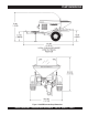
PUMP DIMENSIONS Figure 1. C30HDZ Concrete Pump Dimensions MAYCO C30HDZ PUMP — OPERATION AND PARTS MANUAL — REV.
SAFETY MESSAGE ALERT SYMBOLS FOR YOUR SAFETY AND THE SAFETY OF OTHERS! Safety precautions should be followed at all times when operating this equipment. Failure to read and understand the Safety Messages and Operating Instructions could result in injury to yourself and others. This Owner's Manual has been developed to provide complete instructions for the safe and efficient operation of the Mayco Model C30HDZ Concrete Pump.
SAFETY MESSAGE ALERT SYMBOLS WARNING - ROTATING PARTS NEVER operate equipment with covers, or guards removed. Keep fingers, hands, hair and clothing away from all moving parts to prevent injury. CAUTION - ACCIDENTAL STARTING CAUTION - RESPIRATORY HAZARDS ALWAYS wear approved respiratory protection. CAUTION - SIGHT AND HEARING HAZARDS ALWAYS place the Engine ON/OFF switch in the OFF position and remove the ignition key when the pump is not in use.
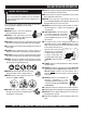
RULES FOR SAFE OPERATION DANGER - Read This Manual! Failure to follow instructions in this manual may lead to serious injury or even death! This equipment is to be operated by trained and qualified personnel only! This equipment is for industrial use only. The following safety guidelines should always be used when operating the Mayco C30HDZ Concrete Pump: General Safety ■ DO NOT operate or service this equipment before reading this entire manual.
RULES FOR SAFE OPERATION ■ CAUTION must always be observed while servicing this pump. Rotating parts can cause injury if contacted. ■ A copy of this manual shall accompany the pump at all times. ■ ALWAYS stored the pump in a clean, dry location out of the reach of children. ■ ALWAYS use extreme care when operating near obstructions, on slippery surfaces, grades and side slopes. ■ DO NOT disconnect the hose couplings or nozzle while they are under pressure.
RULES FOR SAFE OPERATION Maintenance Safety Emergencies ■ NEVER lubricate components or attempt service on a running machine. ■ ALWAYS know the location of the nearest fire extinguisher and first aid kit. Know the location of the nearest telephone. Also know the phone numbers of the nearest ambulance, doctor and fire department. This information will be invaluable in the case of an emergency. ■ ALWAYS allow the machine a proper amount of time to cool before servicing.
NOTES MAYCO C30HDZ PUMP — OPERATION AND PARTS MANUAL — REV.
TOWING GUIDELINES Towing Safety Precautions CAUTION - Local Towing Regulations Check with your county or state safety towing regulations department before towing your concrete pump. To reduce the possibility of an accident while transporting the pump on public roads, always make sure that the trailer and the towing vehicle are in good operating condition and both units are mechanically sound.
TOWING GUIDELINES Figure 2 shown below illustrates the typical towing application that should be used when towing the pump. Figure 2. Towing Applications MAYCO C30HDZ PUMP — OPERATION AND PARTS MANUAL — REV.
TRAILER SAFETY GUIDELINES Trailer Safety Precautions CAUTION - General Trailer Safety ALWAYS make sure that the trailer is in good operating condition. Check the tires for proper inflation and wear. Also check the wheel lug nuts for proper tightness. The following list defines the major trailer components: 1. Fuel Cell – Provides an adequate amount of fuel for the equipment in use. Fuel cells must be empty when transporting equipment. 2.
TRAILER SAFETY GUIDELINES Tires/Wheels/Lug Nuts Tires and wheels are a very important and critical components of the trailer. When specifying or replacing the trailer wheels it is important the wheels, tires, and axle are properly matched. CAUTION - General Trailer Safety DO NOT attempt to repair or modify a wheel. DO NOT install an inter-tube to correct a leak through the rim.
TRAILER SAFETY GUIDELINES Lug Nut Torque Requirements It is extremely important to apply and maintain proper wheel mounting torque on the trailer. Be sure to use only the fasteners matched to the cone angle of the wheel. Proper procedure for attachment of the wheels is as follows: 1. Start all wheel lug nuts by hand. 2. Torque all lug nuts in sequence (Figure 4). DO NOT torque the wheel lug nuts all the way down. Tighten each lug nut in 3 separate passes as defined by Table 4. 3.
NOTES MAYCO C30HDZ PUMP — OPERATION AND PARTS MANUAL — REV.
OPERATION AND SAFETY DECALS Figure 5 display's the operation and safety decals as they appear on the concrete pump, should any of these decals become damaged or unreadable, contact the Multiquip Parts Department for a replacement set. CAUTION CAUTION ! When the pump, manifold or delivery system plugs, do not disconnect the delivery system clamps or open the manifold.
IMPORTANT HAND SIGNALS Figure 6 display's the basic hand signals commonly used in concrete pumping operations. Figure 6. Operation Hand Signals MAYCO C30HDZ PUMP — OPERATION AND PARTS MANUAL — REV.
PUMP COMPONENTS 0 C Y A M Z HD 30 C- 7 8 24 9 10 13 12 6 5 16 4 11 3 15 17 1 19 2 18 25 22 20 21 23 Figure 7. Major Pump Components PAGE 22 — MAYCO C30HDZ PUMP — OPERATION AND PARTS MANUAL — REV.
PUMP COMPONENTS Figure 4 illustrates the location of the major components for the C30HDZ Concrete Pump. The function of each component is described below: 11. Fuel Tank/Cap – Fill with unleaded fuel. Fuel tank (cell) holds approximately 11 gallons (41 liters). DO NOT top off fuel. Wipe up any spilled fuel immediately 1. Discharge Cone – Connect 3" elbow to this discharge port, then connect 3" x 2" reducer to elbow. 12. Tow End Jack Stand – Use this jack stand to level and support the pump. 2.
CONTROL BOX COMPONENTS Figure 8 illustrates the location of the major components for the C30HDZ Control Box. The function of each component is described below: 4 2 3 6 5 quart z 7 8 1 Figure 8. Pump Control Box Components 1. Throttle Control Knob – This is a variable speed type control. Turning the throttle lock left (CCW) unlocks the throttle allowing the throttle control cable to be pulled out to the desired position.
ENGINE COMPONENTS REAR VIEW 12 FRONT VIEW 10 13 14 6 1 7 9 8 3 5 11 4 Figure 9. Deutz Model F2L01011F Basic Engine Components Figure 9 illustrates the location of the basic components for the Deutz Model F2L01011F Engine. The function of each component is described below: 7. Cooling Fan Blades – Make sure that the blades of the cooling fan are not bent or broken. A damaged fan blade can cause the engine to run hot and overheat. 1.
GENERAL INFORMATION The following operating principles and operating suggestions should prove helpful in the successful operation of your concrete pump. Your new “small line” concrete pump has been designed to give you many years of service when operated properly. A study of the following paragraphs is important to the successful operation of your new Direct-flow Concrete Placer.
HOW IT WORKS The C30HDZ concrete pump has one main pumping piston which is valved by means of two ball checks. (A inlet, and B outlet.) The secondary piston is used as a compensator piston to smooth out the pulsations of a single piston action. Note: The compensator will not start operating until material is pumped into the line and back pressure develops. The compensator spring, which is installed on the compensator piston rod, deflects with each piston stroke.
HOW IT WORKS The pumping piston (Figure 11) is forcing the material past ball (B) and out to the nozzle, also seating ball A so that the material will not flow back to the hopper. This action also fills the compensating piston for the next stroke. Figure 11. Pumping Pistons Figure 12 shows the relationship between the return spring, the compensator spring and the rocker arm to maintain a smooth performance. DO NOT tighten the bolt (Item 1) completely, the rod end must be able to move.
OPERATING INFORMATION C. If it is necessary to wait 10 minutes or more for another load of concrete, it is wise to start the pump and pump 6 or 8 strokes every 5 minutes to prevent setting of the mix in the system. If waiting time is excessive, it would be wise to wash out the pump and hoses and start over when the new truck arrives. OPERATING SUGGESTIONS 1. A well-planned location of the pump and routing of the hose before starting a pour may save subsequent moves throughout the job. 2.
OPERATING INFORMATION WARNING - Hose Blockage Hazard If you repeatedly pull the throttle all the way out and try to force your pump to push through blockages due to separation of material in the hose or manifold, you will soon have breakdowns and costly repairs which are not covered under warranty. If a blockage occurs, find where it is and clear it before further pumping. DO NOT increase the engine speed to clear the blockage. Increasing the engine speed will only compound the problem.
OPERATING INFORMATION 6. If a blockage occurs in a hose, “walk the hose” until you find the point of trouble.The hose will be soft immediately past the blockage. If this happens at the start, disconnect the hose at the first coupling past the blockage. Elevate the hose at that point with the blockage area hanging down.
OPERATING INFORMATION Down-Hill Pumping Valve Seats Downhill pumping can be difficult on some jobs. It is suggested that a sponge 2”x 4”x 6” be placed in the hose before the start of pumping.Wet the sponge before placing it in the hose. Reference the Operating Suggestions at the start of this section for slurry procedures. If the volume at the end of hose starts to decrease gradually and eventually almost stops, it is quite likely that the valve seats have had excessive wear and need replacement.
OPERATING INFORMATION Cam Roller If the cam roller does not ride on the cam profile smoothly, it may be caused by insufficient line back-pressure; e.g., a wet mix with only 50 feet of hose. Add more hose as necessary. It can also be caused by cavitation or the passing of over-sized aggregates through the valving, causing it to skip. Snap-Joint When using Snap-Joint couplings with gaskets to join hose, see that they are washed clean after each job.
INSPECTION CAUTION - General Saftey Guidelines NEVER operate the pump in a confined area or enclosed area structure that does not provide ample free flow of air. Engine Oil Check 1. To check the engine oil level, place the pump on secure level ground with the engine stopped. 2. Remove the dipstick from its holder (Figure 13) and wipe it clean. OIL FILLER HOLE ALWAYS wear approved eye and hearing protection before operating the pump . NEVER operate the pumps's engine with the engine hood removed.
INSPECTION Gasoline Check Lubrication Box 1. Remove the gasoline cap located on top of fuel tank. The C30HDZ model features a fully enclosed lubrication box, which utilizes the "splash" method of lubrication. 2. Handle Fuel in a safety container. If the container does not have a spout use a funnel. 3. Visually inspect to see if fuel level is low. If fuel is low, replenish with unleaded fuel.When refueling, be sure to use a strainer for filtration. DO NOT top-off fuel. Wipe up any spilled fuel. 4.
STARTUP/SHUTDOWN PROCEDURES Starting CAUTION - General Saftey DO NOT attempt to operate this concrete pump until the Safety, General Information and Inspection sections have been read and understood. 3. Insert the ignition key into the ignition switch (Figure 22), turn the key to the ON position, then to the START position, release the key when the engine starts. Figure 22. Ignition Switch 1. Turn the throttle control knob fully counter-clockwise to set the engine speed to IDLE. (Figure 17.) 6.
MAINTENANCE (PUMP) Preventive Maintenance General Clean-up Procedure It is extremely important to maintain this pump due to the highly abrasive nature of concrete material. 1. Ensure that there is no blockage in the hose and line (Pumping Tips, step 8) or in the manifold (Pumping Tips, step 7). If a blockage exists, clear it to ensure proper operation the next time it is used.
MAINTENANCE (PUMP) Sponge Clean-out Procedure Lubrication Box This section will explain the recommended procedure for using a sponge to clean out the hose lines. The C30HDZ model features a fully enclosed lubrication box, which utilizes the "SPLASH" method of lubrication. CAUTION - Clearing The Pump NEVER use muriatic acid to clear the pump. Acid will dissolve the chrome finish on the pumping cylinder.
MAINTENANCE (PUMP) Crankshaft and Cam Assembly Procedure Ball and Seat Replacement Procedure 1. Set bearing block (P/N EM14303) into hydraulic press. Place bearing cup into bearing block and press in evenly. Bearing cup should be aligned equally on both sides of bearing block. 1. Remove 3”x 2” reducer and 3” elbow from the pump outlet. Remove exhaust gate andY-manifold (secondary manifold). Check ball seat and ball stop pin for wear. If any wear is detected, the part should be replaced.
MAINTENANCE (PUMP) Clutch Lining Replacement (For P/N EM14320 Clutch Assembly Only) The normal lining thickness measures 3/16 of an inch. If the clutch starts to slip or make an usual noise, it may be necessary to replace the lining. Please note that the lining retaining rivets should not be exposed to the rotating weight. The following procedure will assist you in replacing the lining. 1. Remove worn out lining and rivets. Check clutch springs and flyweights for wear. 2. Cut 1/8 in.
MAINTENANCE (PUMP) Bearing Installation 1. Install the bearing components on the crankshaft making full contact with the back side of the crank disc as indicated the symbol #. See Figure 25 below. 2. Install the bushing in the cam weldment and slide it onto the crankshaft until contact is made with the bearing spacer. NOTE It is important that the Bearing Assembly is installed properly. 3. Tighten the 3 allen head bolts “A” while exerting pressure on the bushing towards the bearing spacer. Figure 25.
MAINTENANCE (PUMP) 3. 1. After the bearing assembly has been is installed , remove the three “dog type” allen head set screws (B) to allow detents to be drilled. See Figure 26 below. If this procedure is not followed closely the heavy loading of the bearing during pumping operation causes the Timken™ cone bearings to create lateral forces which will move the taper bushing and allow the Timken™ cone bearings to separate from the race and subsequently fail.
MAINTENANCE (PUMP) Figure 27. V-Belt and Drive Chain Adjustment V-Belt And Drive Chain Adjustment 1. Loosen the pillow bearing bolts (Figure 27) only to the point where the bolts will remain snug. 2 Unlock the two pusher bolt lock nuts. 3. Turn each pusher bolt clockwise an equal amount until the chain is to proper adjustment of approximately 3/8 to 1/2 in. slack in the chain. It is very important that the pulley side and the chain side (pillow block bearings) are within 1/16” of an equal distance. 4.
MAINTENANCE (PUMP) Roller Chain Application Installation and Drive Alignment A properly selected, installed and maintained drive chain (Figure 28) is an extremely versatile means of power transmission. It is possible, however, to greatly reduce a chain’s life and even induce failure if the chain is abused through improper installation, operating or maintenance procedures. In certain applications, failure can lead to personal injury or property damage.
MAINTENANCE (PUMP) Drive Chain Lubrication As a chain articulates in entering and leaving a sprocket, there is relative movement between pin and bushing surfaces. These surfaces wear causing chain elongation. If a lubricant film can be maintained between the pin and bushing, the wear rate is very slow and the chain wear life very long. Maintaining the oil film is relatively simple at low speeds but becomes increasingly difficult as the speed increases.
MAINTENANCE (PUMP) Assembling and Disassembling Drive Chain CAUTION - DRIVE CHAIN SAFETY You may be seriously injured if you attempt to install the drive chain while the pump is running. Turn OFF the engine and lock out gears and sprockets before attempting installation. Once installed, the drive chain must be guarded to prevent personal injury or properly damage in the event the chain separates during operation. NEVER run pump with drive chain guard removed.
ENGINE TROUBLESHOOTING Practically all breakdowns can be prevented by proper handling and maintenance inspections, but in the event of a breakdown, please take a remedial action following the diagnosis based on the Engine Troubleshooting (Table 6) information shown below and on the proceeding page. If the problem cannot be remedied, please leave the unit just as it is and consult our company's business office or service plant. TABLE 6.
ENGINE TROUBLESHOOTING TABLE 6. ENGINE TROUBLESHOOTING (CONTINUED) SYMPTON Low engine power, output and speed. Low engine power output and low speed, black exhaust smoke. POSSIBLE PROBLEM SOLUTION Fuel tank empty? Replace fuel filter. Fuel filter clogged? Replace fuel filter. Fuel tank venting is inadequate? Ensure that tank is adequately vented. Leaks at pipe unions? Check threaded pipe unions tape and tighten unions a required.
NOTES MAYCO C30HDZ PUMP — OPERATION AND PARTS MANUAL — REV.
WIRING DIAGRAM Figure 32. Wiring Diagram PAGE 50 — MAYCO C30HDZ PUMP — OPERATION AND PARTS MANUAL — REV.
WIRING DIAGRAM (TAIL LIGHTS) Figure 33. Trailer Tail Lights Wiring Diagram MAYCO C30HDZ PUMP — OPERATION AND PARTS MANUAL — REV.
APPENDIX — SLUMP TEST PROCEDURE 1. To obtain a representative sample (concrete), take several samples at three or more regular intervals throughout the discharge of the mixer or truck. DO NOT take samples at the beginning or end of the discharge. 2. Dampen the inside of the cone and place it on a smooth, moist, nonabsorbent, level surface large enough to accommodate both the slumped concrete and the slump cone. Stand on the “foot pieces” throughout the test procedure to hold the cone firmly in place. 3.
APPENDIX — CONCRETE MIX INFORMATION The following information has been extracted from actual testing laboratory reports. The purpose of this printing is only to help create a better understanding of the importance of uniform gradation and proportioning of materials which affect pumpability of concrete mixes. These weights and proportions illustrate that when the sieve analysis is ideal, the sand/rock ratio can be adjusted (65% sand 35% rock) and pumpability should be excellent.
APPENDIX — CONCRETE MIX INFORMATION A.S.T.M. STANDARD SPECIFICATION FOR GRADING AGGREGATE PAGE 54 — MAYCO C30HDZ PUMP — OPERATION AND PARTS MANUAL — REV.
APPENDIX — CONCRETE MIX INFORMATION Consolidated Rock Products Co., Division of Tests 3/8” Pea Gravel STANDARD PUMP MIXES (one-half inch minus) NOTE: All weights shown are one cubic yard with S.S.D. aggregates. CRP Mix Number 6004 .......................... 6005 .............................6006 .......................... 6007 Design Slump (in.) 6” (15 cm) .................6” Cement, SACK. 7.0 ................................ 7.0 ......................................7.0 .............................
APPENDIX — RECOMMENDED SHOTCRETE SYSTEM RECOMMENDED SHOTCRETE SYSTEM 1-800 -30-M 10 AYCO 0 C Y A M N HD 30 C- 1 3 2 3 1/2 STANDARD AIR HOSE 7 8 11 9 13 14 15 AIR COMPRESSOR (125 TO 250 CFM) 10 3/4 STANDARD AIR HOSE Figure 35. Shotcrete System PAGE 56 — MAYCO C30HDZ PUMP — OPERATION AND PARTS MANUAL — REV.
APPENDIX — RECOMMENDED SHOTCRETE SYSTEM RECOMMENDED SHOTCRETE SYSTEM NO. 1 PART NO. PART NAME EM28904 ........... 3" “B” COUPLING 2 EM23946 ........... 3"-90° ELBOW 3 EM28903 ........... 2 1/2" S/J COUPLING 4 EM28005DD ...... 3"X 2 1/2 REDUCER 5 EM28061 ........... 2 1/2"X 10FT. PIPE 6 EM24849 ........... 2 1/2"X 50FT. HOSE 7 EM28001DD ...... 2 1/2"X 2" REDUCER 8 EM23815D ........ 2 1/2"X 2" REDUCER QTY. REMARKS W/AIR VIBRATOR 9 EM28902 ........... 2" S/J COUPLING 10 EM23101 ...........
APPENDIX — RECOMMENDED SHOTCRETE ACCESSORIES RECOMMENDED SHOTCRETE ACCESSORIES Figure 36. Shotcrete System Accessories NOTE Use a 1-3/8" rubber nozzle tip for a wide spray pattern. Use a 1-1/4" rubber nozzle tip for a narrow spray pattern. DO NOT INSTALL THE NOZZLE AT THE END OF THE HOSE UNTIL THE FIRST MATERIAL HAS PASSED THROUGH THE ENTIRE HOSE LENGTH. Disassemble and clean the nozzle assembly thoroughly after each job. Grease all threads before reassembly.
APPENDIX — RECOMMENDED SHOTCRETE ACCESSORIES RECOMMENDED SHOTCRETE ACCESSORIES NO. 1 2 3 4 5 6 7 8 9 10 11 12 * 13 * 14 * 15 * 16 * 17 * 18 * 19 * 20 21 PART NO. EM26107 EM231011 EM132 EM23407 EM23408 EM23411 EM912073 EM23409 EM923346 EM406 EM23818 EM24841 EM23845 EM23802 EM23803 EM20816 EM23804 EM23805 EM23806 EM23807 EM911076 EM23808 PART NAME QTY.
EXPLANATION OF CODE IN REMARKS COLUMN The following section explains the different symbols and remarks used in the Parts section of this manual. Use the help numbers found on the back page of the manual if there are any questions. NOTICE The contents and part numbers listed in the parts section are subject to change without notice. Multiquip does not guarantee the availability of the parts listed. SAMPLE PARTS LIST NO. 1 2% 2% 3 4 PART NO. PART NAME QTY. REMARKS 12345 BOLT......................1 .....
SUGGESTED SPARE PARTS P/N EM14904 EM18804 EM14818 EM14903 EM18801 EM14308 EM26313 EM26314 EM14334 EM14408 EM903092 EM14315 EM14842 EM14843 EM26310 EM18409 EM20763 EM20328TKIT EM28004DD EM23946 EM28904 EM289041 EM14159 NOTE C30HDZ CONCRETE PUMP C30HDZ CONCRETE PUMP W/ SYSTEM W/ SYSTEM 1 Units 3 Units DESCRIPTION QTY.
NAMEPLATE AND DECALS NAME PLATE AND DECALS 4 3 0 4 C Y A 13 M 11 12 Z HD 30 C- 3 DECAL KIT 5 8 10 7 6 1 2 PAGE 62 — MAYCO C30HDZ PUMP — OPERATION AND PARTS MANUAL — REV.
NAMEPLATE AND DECALS NAME PLATE AND DECALS NO 1 * 2 * 3 * 4 * 5 6 * 7 8 * 9 * 10 * 11 12 13 PART NO DCL152 EM932 EM1028 508594 EM513119 EM513165 513163 34536 TBD DCLC30HDNIKIT EM514187 35137 PART NAME QTY. REMARKS DECAL, CAUTION OIL LEVEL 1 DECAL, CAUTION, MANIFOLD 1 DECAL, MULTIQUIP MAYCO 2 DECAL, CAUTION READ MANUAL 2 DECAL, C30HDZ 2 DECAL, MAINTENANCE 1 DECAL, NAME PLATE ............................. 1 ........... CONTACT PARTS DEPT.
COMPENSATOR PISTON ROD ASSY. COMPENSATOR PISTON ROD ASSY. PAGE 64 — MAYCO C30HDZ PUMP — OPERATION AND PARTS MANUAL — REV.
COMPENSATOR PISTON ROD ASSY. COMPENSATOR PISTON ROD ASSY. NO. 1 1A+ 2 3 4 5 6 7 8 * 9 * 10 * 11 * 12 * 13 14 15 16 17 18 19 20 21 22 23 24 25 26 26 27 28 29 30 31 32 33 34 35 PART NO. EM14805 EM148053 EM968446 EM14332 EM14331 EM14333 EM14806 EM505490 EM903163 EM20814 EM20813 EM903162 EM20816 EM916001 EM510266 EM621 492584 EM14335 EM14336 EM505489 EM14334 EM18409 EM98032 EM14407 EM14410 EM14408 EM14411 EM98051 EM14412 EM18409 EM14413 EM18800HD EM26525 EM968446 EM16493 EM148053 EM20328TKIT PART NAME QTY.
C-30HDN PUMP — CONNECTING ROD - DRIVE SIDE ASSY. CONNECTING ROD - DRIVE SIDE ASSY. PAGE 66 — MAYCO C30HDZ PUMP — OPERATION AND PARTS MANUAL — REV.
C-30HDN PUMP — CONNECTING ROD - DRIVE SIDE ASSY. CONNECTING ROD - DRIVE SIDE ASSY. NO. PART NO. PART NAME QTY.
ROCKER ASSY. ROCKER ASSY. 7 LUBRICATION POINT 1 6 31 27 7 25 35 45 7 24 1 23 A B C 22 LUBRICATION POINT 21 8 20 14 31 30 23 24 41 36 7 28 46 37 8 40 KIT 38 37 LUBRICATION POINT 3 4 2 LUBRICATION POINT 2 1 PART OF FRAME LUBRICATION POINT 17 13 43 8 5 19 16 27 15 NOTES: 1 2 7 12 A. LONG STROKE SETTING. HIGHER VOLUME, LOWER PSI. B. STANDARD SETTING, NORMAL. C. SHORT STROKE SETTING. REDUCED VOLUME, HIGHER PSI.
ROCKER ASSY. ROCKER ASSY. NO. 1 2 3 4 5 6 7 8 9 10 11 12 13 14 15 16 17 19 20% 21% 22% 23% 24% 25 27#+ 28 30 31 35 36 37 38 40 41 42 43 44 45 46 PART NO. EM14329 EM14116 EM963180 EM923350 EM14846 EM133 EM603 EM916001 EM903092 EM20347 EM402434 EM20344 EM916001 EM417 EM402456 EM923157 EM20349 EM969038 EM903163 EM20814 EM20813 EM903162 EM20816 EM105 EM203262 EM20364 EM702 EM505490 EM14328 EM402996 EM20336 EM903176 EM20338 EM923348 EM503982 EM98043 EM417 EM202 EM20328TKIT PART NAME QTY.
COUNTER-SHAFT ASSY. COUNTERSHAFT ASSY. 15 9 7 10 LUBRICATION POINT 8 13 2 11 3 6 PART OF FRAME 3 4 1 4 7 2 PART OF FRAME 5 1 LUBRICATION POINT 14 6 12 21 13 6 13 5 22 2 6 6 16 55 NOTES: 1 MASTER LINK SEE CLUTCH ASSEMBLY PAGES 84 AND 85. 2 SEE CRANKCASE ASSEMBLY, HALF LINK 60 PAGES 74 AND 75, 59 61 PAGE 70 — MAYCO C30HDZ PUMP — OPERATION AND PARTS MANUAL — REV.
COUNTER-SHAFT ASSY. COUNTER-SHAFT ASSY. NO. 1 2 3 4 5 6 7 8 9 10 11 12 13 14 15 16 21 22 55 59 60 61 PART NO. EM513073 EM14311 EM124 EM621 EM923346 EM968011 EM916001 EM14316 EM14314 EM14313 EM14315 EM143111 EM130 EM14317 EM123 EM161 EM14318 EM14319 EM14307 EM14308 EM26314 EM26313 PART NAME COUNTER SHAFT CAM BEARING BOLT HEX 1/2 X 13 X 4" WASHER WILLIAMS 1/2" WASHER, LOCK1/2” NUT HEX, 1/2-13 FITTING, GREASE KEY 3/8”X2.
CRANKSHAFT ASSY. CRANKSHAFT ASSY. 57 KIT 25 35 33 LUBRICATION POINT 32 35 28 31 1 24 27 31 34 32 30 29 45 46 50 24 54 23 LUBRICATION POINT 43 26 49 44 55 48 41 56 42 52 58 51 2 NOTES: 24 46 SEE ROCKER ARM ASSEMBLY 1 ITEM 43 FOR ASSOCIATED CRANKSHAFT COMPONENTS. 2 SEE COUNTER-SHAFT ASSEMBLY, ITEM 55 PAGE 72 — MAYCO C30HDZ PUMP — OPERATION AND PARTS MANUAL — REV.
CRANKSHAFT ASSY. CRANKSHAFT ASSY. NO. 23 * 24 * 25 26 27 28 29 * 30 * 31 * 32 * 33 * 34 * 35 * 38 40 41 42# 43 * 44 * 45 * 46 * 48 * 49 * 50 * 51 52 54 55 * 56 * 57 58 PART NO. EM14303 EM702 EM505490 EM129 EM492628 EM968446 EM14324 EM14323 EM14325 EM14326 EM14322 EM98043 EM14306 EM903176 EM402996 EM923348 EM30139 EM14302 EM14300 EM14301 EM703 EM175 EM14304 EM916001 EM128 EM620 EM968013 EM14307 EM14309 EM98043K 492378 PART NAME QTY.
MANIFOLD ASSY. MANIFOLD ASSY. ACCESSORIES 2 14 15 13 5 6 16 12 11 3 8 17 1 24 14 11 23 4 PART OF FRAME 7 26 27 7 9 12 28 31 7 19 21 14 13 18 7 37 38 30 27 26 PART OF FRAME 27 7 32 32 36 33 35 34 PAGE 74 — MAYCO C30HDZ PUMP — OPERATION AND PARTS MANUAL — REV.
MANIFOLD ASSY. MANIFOLD ASSY. NO. 1 2 3 4 5 6 7 8 9 11 12 13 14 15 16 17 18 19 21 23 24 26 27 28 30 31 32 33 34 35 36 37 38 PART NO. EM23946 EM28004DD EM2C0B EM28904 EM18409 EM14843 EM18801 EM18804 EM14801 EM136 EM18409 EM618 EM968266 EM104 EM923348 EM505882 EM14842 EM14818 EM14819A EM18409 EM618 EM137 EM619 EM968446 EM14850 EM963180 EM969038 EM14845 EM135 EM14810 EM451 EM160 EM509329 PART NAME ELBOW 3”X90 DEG.
FRAME ASSY. FRAME ASSY. 26 45 44 LE F 20 39 S T- 21 19 1 IDE 20 21 28 17 40 41 27 46 22 29 43 1 42 18 38 21 35 14 15 20 34 16 33 12 30 36 21 32 37 11 31 23 10 20 8 21 2 3 4 5 2 7 13 IDE RIG H 39 S T- 41 40 NOTES: RUBBER LIGHT SEAL IS 1 INCLUDED WITH ITEM 42 (ROUND STYLE ONLY) 2 FOR AXLE PARTS BREAKDOWN SEE AXLE ASSEMBLY 42 1 PAGE 76 — MAYCO C30HDZ PUMP — OPERATION AND PARTS MANUAL — REV.
FRAME ASSY. FRAME ASSY. NO. PART NO.
AXLE ASSY. AXLE ASSY. PAGE 78 — MAYCO C30HDZ PUMP — OPERATION AND PARTS MANUAL — REV.
AXLE ASSY. AXLE ASSY. NO. 1 2 3 * 4 * 5# 6# 7 8# 9# 10# 11# 12# 13# 14# 15# 16# 17% 18% 19 PART NO. EM26518 EM26615A EM26306 EM968481 EM705 EM26329 EM903113 EM903012 EM26519 EM20612 EM26300 EM903169 EM903168 EM26305 EM20601 EM14600 EM14600A PART NAME QTY. REMARKS CAP 14” CHROME 2 TIRE ASSY. ................................ 2 ........... INCLUDES ITEMS W/ * WHEEL ....................................... 2 ........... CANNOT BE PURCHASED SEPARATELY TIRE 14" ..................................... 2 ...........
MUFFLER, AIR FILTER, AND STOP SWITCH ASSY. MUFFLER, AIR FILTER AND STOP SWITCH ASSY. PAGE 80 — MAYCO C30HDZ PUMP — OPERATION AND PARTS MANUAL — REV.
MUFFLER, AIR FILTER, AND STOP SWITCH ASSY. MUFFLER, AIR FILTER AND STOP SWITCH ASSY. NO. 1 1A 2 3 4 5 6 7 8 9 10 11 * 12 * 13 14 * 15 16 17 * 18 PART NO. EM98076 EM98168 513390 514772 513196 EM14217 EM491873 506257 EM98066 01173940 04172501 01112824 03363577 02165357 02240281 02240285 02240283 02339813 02169927 PART NAME QTY. REMARKS FILTER, AIR 1 PRECLEANER, AIR FILTER 1 BRACKET, AIR CLEANER (PIPE) 1 MUFFLER COVER 1 MUFFLER PIPE .......................................... 1 ...............
CLUTCH ASSY. CLUTCH ASSY. 17 20 18 19 14 11 21 8 9 12 13 15 22 10 9 4 8 3 6 16 5 2 PAGE 82 — MAYCO C30HDZ PUMP — OPERATION AND PARTS MANUAL — REV.
CLUTCH ASSY. CLUTCH ASSY. NO. 1 * 2 * 3 * 4 * 5 * 6 * 8 * 9 * 10 * 11 * 12 * 13 14 15 16 17 18 19 20 21 22 PART NO. 492395 EM923346 EM621 EM26321 EM918050 EM26310 EM902204 EM926066 EM926053 EM508342 EM26322 0166A EM512707 EM26348 EM14320 513199 509252 492625 3019092 492357 2101402 PART NAME QTY. REMARKS SCREW, HHC 1/2- 13X1-3/4” 1 WASHER, LOCK 1/2” 1 WASHER, FLAT 1/2” SPECIAL 1 ROTOR ASSEMBLY 1 CLUTCH SPRING 2 CLUTCH LINING 1 CLUTCH BEARING 2 RETAINING RING 2 RETAINING RING 1 SCREW, HHC M8X25 PI.
ENGINE MOUNTING ASSY. ENGINE MOUNTING ASSY. RADIATOR AND ENGINE MOUNTING 9 8 1 2 1 3 4 4 7 5 7 SECURE TO FRAME 6 PAGE 84 — MAYCO C30HDZ PUMP — OPERATION AND PARTS MANUAL — REV.
ENGINE MOUNTING ASSY. ENGINE MOUNTING ASSY. NO. 1 2 3 4 5 6 7 8 9 PART NO. 492556 492626 513195 EM130 513204 513095 513194 4280937 EM98190 PART NAME QTY. NUT, HEX 1/2 IN. 8 WASHER, LOCK 1/2 IN. 4 ENGINE SUPPORT BLOCK (SIDE) 2 SQUARE HEAD BOLT 1/2 NC X 2-1/2 IN. 6 BOLT 1/2 NC X 5 IN. 2 BOLT, C/T 1/2 NC x 2 IN. 2 ENGINE SUPPORT BLOCK (REAR) 2 OIL COOLER 1 DEUTZ ENGINE 1 REMARKS MAYCO C30HDZ PUMP — OPERATION AND PARTS MANUAL — REV.
THROTTLE ASSY. THROTTLE ASSY. 11 10 6 12 5 4 9 3 2 8 7 13 14 16 15 17 20 18 1 1 31 24 30 1 36 34 32 16 23 35 29 19 33 25 21 22 26 17 27 25 28 37 38 39 NOTES: CONNECT TO CLUTCH 1 SIDE OF ENGINE PAGE 86 — MAYCO C30HDZ PUMP — OPERATION AND PARTS MANUAL — REV.
THROTTLE ASSY. THROTTLE ASSY. NO. 1 2 3 4 5 6 7 8 9 10 11 12 13 14 15 16 17 18 19 20 21 22 23 24 25 26 27 28 29 30 31 32 33 34 35 36 37 38 39 PART NO.
CONTROL BOX MOUNTING BRACKET ASSY. CONTROL BOX MOUNTING BRACKET ASSY. 3 4 1 SECURE TO TOP OF ENGINE 5 2 SECURE TO BELT COVER ON ENGINE quart z 1 NOTES: 1 COMES WITH ENGINE PAGE 88 — MAYCO C30HDZ PUMP — OPERATION AND PARTS MANUAL — REV.
CONTROL BOX MOUNTING BRACKET ASSY. CONTROL BOX MOUNTING BRACKET ASSY. NO. 1 2 3 4 5 PART NO. 492363 492582 506559 492596 513380 PART NAME SCREW, HHC 5/16- 18 X 3/4” NUT, NYLOC 5/16- 18 SCREW, HHC M6 X 20 P-1 WASHER, FLAT 1/4” SUPPORT, CONTROL PANEL QTY. 1 1 1 1 1 REMARKS MAYCO C30HDZ PUMP — OPERATION AND PARTS MANUAL — REV.
CONTROL BOX ASSY. CONTROL BOX ASSY. 1 10 3 8 4 9 3 5 5 2 11 6 2 6 h 4 1 NOTES: LAMP HOLDER INCLUDED 1 WITH ITEMS 13, 14, & 15 INCLUDED WITH ITEM 1, 2 THROTTLE CABLE P/N 510229 INCLUDED WITH ITEM 8, 3 IGNITION SWITCH P/N 10958 INCLUDED WITH ITEM 5, 4 REMOTE OUTLET PLUG P/N Em26789 INCLUDED WITH ITEM 10, 5 PUMPING CONTROL SWITCH P/N 40711 INCLUDED WITH ITEM 4, 6 HOUR METER P/N 506222 PAGE 90 — MAYCO C30HDZ PUMP — OPERATION AND PARTS MANUAL — REV.
CONTROL BOX ASSY. CONTROL BOX ASSY. NO. 1 3 4 5 6 7 8 9 10 11 13 14 15 PART NO. 510229 01180677 506222 EM26789 EM501102 EM491089 0302735 0302736 EM40711 EM513076 01180383 01180384 01180382 PART NAME THROTTLE CABLE ASSY. 12 VDC BULB HOURMETER RECEPTACLE (REMOTE) LOCK, ACCELERATOR COUPLING SCREW, 1/4“ IGNITION SWITCH IGNITION SWITCH KEY SWITCH, PUMPING CONTROL CONTROL BOX RED PILOT LENS (OIL PRESSURE) RED PILOT LENS (BATTERY) RED PILOT LENS (OIL TEMPERATURE) QTY.
BATTERY ASSY. BATTERY ASSY. PAGE 92 — MAYCO C30HDZ PUMP — OPERATION AND PARTS MANUAL — REV.
BATTERY ASSY. BATTERY ASSY. NO. 1 2 3 4 5 6 7 8 9 PART NO. EM14705 EM506266 34506 EM492541 EM923023 EM923343 EM20720 EM505624 EM491344 PART NAME CABLE, POSITIVE BATTERY COVER, POSITIVE TERMINAL BOX, BATTERY NUT, HEX 5/16- 18 WASHER, FLAT 5/16 WASHER, LOCK 5/16 CABLE, NEGATIVE BATTERY COVER, NEGATIVE TERMINAL BATTERY, 12 VOLT QTY. 1 1 1 1 1 1 1 1 1 REMARKS MAYCO C30HDZ PUMP — OPERATION AND PARTS MANUAL — REV.
FUEL TANK ASSY. FUEL TANK ASSY. PAGE 94 — MAYCO C30HDZ PUMP — OPERATION AND PARTS MANUAL — REV.
FUEL TANK ASSY. FUEL TANK ASSY. NO. 1 2 3 4 5 6 7 8 9 10 11 11 PART NO. 6636A TBD TBD TBD 6109152 EM20763 EM513115 EM20426 EM491210 EM505594 EM514722 EM516551 12 14# 15# 16# 17# 18 2108 516568 19633 60058 12009 EM516533 PART NAME QTY. REMARKS HOSE, FUEL LINE 5/16" A/R? CLAMP, HOSE 2 WASHER, FLAT 2 BOLT 2 CLAMP, HOSE 5 FILTER, FUEL 1 ADAPTER NLA ......................................... 1 ................. BEFORE JULY 2005 FITTING 1/4" 1 PLUG, 1/4" 1 PIPE, 5/16 COPPER NLA ........................ 1 .....
HOPPER ASSY. HOPPER ASSY. 3 2 4 5 1 PAGE 96 — MAYCO C30HDZ PUMP — OPERATION AND PARTS MANUAL — REV.
HOPPER ASSY. HOPPER ASSY. NO. 1 2 3 4 5 PART NO. EM14159 EM14141 EM925191 EM104 EM507599 PART NAME HOPPER SCREEN HOPPER PIN, HAIR BOLT, 5/8”-11X2” HEX HEAD WASHER 5/8” FLAT QTY. 1 1 2 3 3 REMARKS MAYCO C30HDZ PUMP — OPERATION AND PARTS MANUAL — REV.
HOOD ASSY. HOOD ASSY. PAGE 98 — MAYCO C30HDZ PUMP — OPERATION AND PARTS MANUAL — REV.
HOOD ASSY. HOOD ASSY. NO. 1 2 3 4 5 6 7 8 9 10 11 12 12 PART NO. 503723 491010 EM14140 490937 EM406 EM124 EM963003 EM923057 29057 EM969079 RAL1003S RAL1003G RAL1003Q PART NAME RIVET LATCH KIT HOOD ASSY. BUMPER, RUBBER NUT 1/2”-13 HEAVY HEX BOLT 1/2” DIA-NC X4” G5 SCREW, HHC 1/4-20 X 3/4 WASHER MANUAL HOLDER NUT LOC NYLON 1/4 PAINT, SPRAY CAN 12 OZ. (YELLOW) PAINT, GALLON (YELLOW) PAINT, QUART (YELLOW) QTY. 4 2 1 2 2 2 3 3 1 3 AR AR AR REMARKS MAYCO C30HDZ PUMP — OPERATION AND PARTS MANUAL — REV.
LUBRICATION PANEL ASSY. LUBRICATION PANEL ASSY. NOTE POSITION Grease daily, two to three shots of #2 multi-purpose automotive grease. Over-greasing any bearing will not damage the machine. LOCATION LENGTH OF LINES 1 ....................................................COMPENSATOR ROD ........................................................................ 28" 2 ....................................................COMPENSATOR ROD ........................................................................
LUBRICATION PANEL ASSY. LUBRICATION PANEL ASSY. NO. 1 * 2 * 3 * 4 * 5 * 6 * 7 * 8 PART NO. EM916001 EM505489 505534 EM505516 EM490531 EM491028 EM505490 EM512659 PART NAME QTY. REMARKS FITTING, GREASE 1/8" NPT 14 STRAIGHT FITTING 1/8" NPT 13 COUPLING W/NUT 1/8' NPT 14 PLASTIC HOSE LINE 1/4" DIA. ................ AR ......... 1FT=1PC PROTECTIVE SLEEVE 3/8" (HOSE) ......... AR......... 1FT=1PC TIE-WRAP 2.5 x 95 MM AR ADAPTER, 90 DEGREE ELBOW 1 KIT, LUBRICATION ........................................ 1......
REMOTE CONTROL CABLE ASSY. REMOTE CONTROL CABLE ASSY. 3 1 9 4 2 2 5 6 1 8 7 NOTES: 1 INCLUDED WITH ITEM 1. 2 CORD ASSY. ITEM 9 INCLUDES ITEMS WITHIN DASHED LINES. PAGE 102 — MAYCO C30HDZ PUMP — OPERATION AND PARTS MANUAL — REV.
REMOTE CONTROL CABLE ASSY. REMOTE CONTROL CABLE ASSY. NO. 1 * 2 * 3 * 4 * 5 * 6 * 7 8 9 PART NO. EM16753 EM16754 EM16756 EM491897 EM26791 EM26790 EM26793 EM26792 EM26788 PART NAME QTY. REMARKS JUNCTION BOX 1 SWITCH, MICRO 1 GUARD SWITCH - ALUMINUM 1 CONNECTOR, 3/16 RING 2 GRIP CORD SEAL 1 CORD 25' MX P/E 1 ADAPTER CORD GRIP 1/2" 1 ADAPTER CORD 100 FT. 1 REMOTE W/ 25' CORD ONLY ....................... 1......... INCLUDES ITEMS W/ * MAYCO C30HDZ PUMP — OPERATION AND PARTS MANUAL — REV.
TERMS AND CONDITIONS OF SALE — PARTS PAYMENT TERMS 5. Parts must be in new and resalable condition, in the original Multiquip package (if any), and with Multiquip part numbers clearly marked. 6. The following items are not returnable: Multiquip reserves the right to quote and sell direct to Government agencies, and to Original Equipment Manufacturer accounts who use our products as integral parts of their own products. a. SPECIAL EXPEDITING SERVICE Terms of payment for parts are net 30 days.
MAYCO PUMP WARRANTY MECHANICAL DRIVE MODELS HYDRAULIC DRIVE MODELS MAYCO PUMP, hereinafter referred to as “Manufacturer’, warrants each new Mayco Pump sold by the manufacturer to be free from defects in material and workmanship, under normal use and service, for a period of one year after the date of delivery to the original retail purchaser.
OPERATION AND PARTS MANUAL HERE’S HOW TO GET HELP PLEASE HAVE THE MODEL AND SERIAL NUMBER ON-HAND WHEN CALLING UNITED STATES Multiquip Corporate Office 18910 Wilmington Ave. Carson, CA 90746 Contact: mq@multiquip.com MQ Parts Department Tel.