OPERATION AND PARTS MANUAL MODELS MC94S MC94P CONCRETE MIXERS Revision #9 (09/15/11) To find the latest revision of this publication, visit our website at: www.multiquip.com THIS MANUAL MUST ACCOMPANY THE EQUIPMENT AT ALL TIMES.
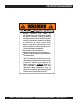
PROPOSITION 65 WARNING Engine exhaust and some of its constituents, and some dust created by power sanding, sawing, grinding, drillingandotherconstructionactivities contains chemicals known to the State of California to cause cancer, birth defects and other reproductive harm. Some examples of these chemicals are: Leadfromlead-basedpaints. Crystallinesilicafrombricks. Cementandothermasonryproducts. Arsenicandchromiumfromchemically treatedlumber.
NOTES MC94P/S CONCRETE MIXERS — OPERATION AND PARTS MANUAL — REV.
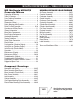
MC94P/S CONCRETE MIXER — TABLE OF CONTENTS MQ Multiquip MC94P/S Concrete Mixers Proposition 65 Warning ............................................. 2 Table Of Contents ..................................................... 4 Parts Ordering Procedures ....................................... 5 Specifications ............................................................ 6 Dimensions (Mixer) ................................................... 7 Safety Message Alert Symbols .................................
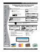
www.multiquip.com PARTS ORDERING PROCEDURES Ordering parts has never been easier! Choose from three easy options: Order via Internet (Dealers Only): Best Deal! Effective: January 1st, 2006 If you have an MQ Account, to obtain a Username and Password, E-mail us at: parts@multiquip. com. Order parts on-line using Multiquip’s SmartEquip website! ■ View Parts Diagrams ■ Order Parts ■ Print Specification Information To obtain an MQ Account, contact your District Sales Manager for more information.
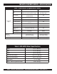
MC94P/S CONCRETE MIXER — SPECIFICATIONS Table 1. Specifications (Engines/Electric Motor) Model HONDA GX240K1QA2 Baldor 35LYL229 Type Air-cooled 4 stroke, Single Cylinder, OHV, Horizontal Shaft Gasoline Engine 1.5 HP, Single-phase 115/230 VAC, Electric Motor Bore X Stroke 2.90 in. X 2.30 in. (73 mm x 58 mm) N/A Displacement 14.81 cc N/A 8.0 H.P./3600 R.P.M. 1.5 HP/1725 R.P.M. Approx. 1.59 U.S.
MC94P/S CONCRETE MIXER — DIMENSIONS (MIXER) See Table 2 for mixer dimensions Figure 1. Mixer Dimensions MC94P/S CONCRETE MIXERS — OPERATION AND PARTS MANUAL — REV.
MC94P/S CONCRETE MIXER — SAFETY MESSAGE ALERT SYMBOLS FOR YOUR SAFETY AND THE SAFETY OF OTHERS! Safety precautions should be followed at all times when operating this equipment. Failure to read and understand the Safety Messages and Operating Instructions could result in injury to yourself and others. NOTE This Owner's Manual has been developed to provide complete instructions for the safe and efficient operation of the Multiquip Model MC94P (Plastic) and MC94S (Steel) Concrete Mixers.
MC94P/S CONCRETE MIXER — RULES FOR SAFE OPERATION DANGER: Failure to follow instructions in this manual may lead to serious injury or even death! This equipment is to be operated by trained and qualified personnel only! This equipment is for industrial use only. The following safety guidelines should always be used when operating the Multiquip MC94P/S Concrete Mixers: GENERAL SAFETY ■ DO NOT operate or service this equipment before reading this entire manual.
MC94P/S CONCRETE MIXER — RULES FOR SAFE OPERATION ■ NEVER run engine without air cleaner. Severe engine damage may occur. ■ ALWAYS read, understand, and follow procedures in Operator’s Manual before attempting to operate equipment. ■ ALWAYS be sure the operator is familiar with proper safety precautions and operations techniques before using roller. ■ ALWAYS store equipment properly when it is not being used. Equipment should be stored in a clean, dry location out of the reach of children.
MC94P/S CONCRETE MIXER — OPERATION AND SAFETY DECALS Machine Safety Decals The Multiquip MC94P/S mixers are equipped with a number of safety decals (Figure 1A). These decals are provided for operator safety and maintenance information. The illustration below and on the next page shows these decals as they appear on the machine. Should any of these decals become unreadable, replacements can be obtained from your dealer. Figure 1A.
MC94P/S CONCRETE MIXER — GENERAL INFORMATION Ensure that the extension cable is carefully laid out avoiding wet areas, sharp edges and locations where vehicles might run over it. Avoid allowing the extension cable to be trapped underneath the mixer. Application This mixer is only intended for the production of concrete. The mixer must be used for its intended purpose and is not suitable for the mixing of flammable or explosive substances. The mixer must not be used in an explosive atmosphere.
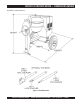
MC94P/S CONCRETE MIXER — MIXER BASIC COMPONENTS Figure 2. Mixer Major Components 1. Steel Mixing Drum — The Multiquip MC94S uses a 6 cu. ft steel mixing drum. This drum is to be used for mixing of concrete. Always clean the drum after each use. DO NOT use this mixing drum for the mixing of volatile liquids. 9. 2. Plastic Mixing Drum — The Multiquip MC94P uses a 6 cu. ft plastic mixing drum. This drum is to be used for mixing of concrete. Always clean the drum after each use.
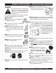
MC94P/S CONCRETE MIXER — BASIC ENGINE COMPONENTS Honda GX Series Engine Shown Figure 3. Engine Controls and Components INITIAL SERVICING 5. The engine (Figure 3) must be checked for proper lubrication and filled with fuel prior to operation. Refer to the manufacturers Engine manual for instructions & details of operation and servicing. Fuel Valve Lever – OPEN to let fuel flow, CLOSE to stop the flow of fuel. 6. Choke Lever – Used in the starting of a cold engine, or in cold weather conditions.
MC94P/S CONCRETE MIXER — HANDWHEEL ASSEMBLY Assembly The MC94P/S concrete mixers are shipped with the handwheel detached. Attach the handwheel to the mixer as shown in Figure 4. Figure 4. Handwheel Assembly MC94P/S CONCRETE MIXERS — OPERATION AND PARTS MANUAL — REV.
MC94P/S CONCRETE MIXER — TOWING GUIDELINES Towing Safety Precautions CAUTION: ■ Check with your county or state safety towing regulations department before towing your mixer. ■ Check wheel mounting lug nuts with a torque wrench. Torque wheel lug nuts as described in the maintenance section of this manual. ■ Check tightness of U-clamp nuts, torque suspension hardware as referenced in the maintenance section of this manual. ■ Avoid sudden stops and starts. This can cause skidding, or jackknifing.
MC94P/S CONCRETE MIXER — SAFETY CHAIN CONNECTION CAUTION: NEVER ! tow the mixer with the safety chain removed. The safety chain is intended to prevent complete separation of the mixer from the towing vehicle in the event of a tow bar failure. Reference Figure 5 for the installation of the Safety Chain. Tow Bar to Mixer Connection 1. Insert the tow bar through the round opening at the bottom of the mixer stand.
MC94P/S CONCRETE MIXER — ELECTRIC MOTOR Electric Motor For maintenance care and operation of the electric motor, refer to your electric motor instruction booklet furnished with the electric motor. Protect the electric motor from dust as much as possible and keep ventilating openings clean. CAUTION: ■ DO NOT spray water at any time on the electric motor. Electric Motor Voltage Change Switch 1.
MC94P/S CONCRETE MIXER — ELECTRIC MOTOR Figure 7. Single Phase Electric Motor MC94P/S CONCRETE MIXERS — OPERATION AND PARTS MANUAL — REV.
MC94P/S CONCRETE MIXER — PRE-INSPECTION (GAS ENGINE) Before Starting 1. Read safety instructions at the beginning of manual. 2. Clean the mixer, removing dirt and dust, particularly the engine cooling air inlet, carburetor and air cleaner. 3. Check the air filter for dirt and dust. If air filter is dirty, replace air filter with a new one as required. 4. Check carburetor for external dirt and dust. Clean with dry compressed air. Table 7.
MC94P/S CONCRETE MIXER — INITIAL START-UP (GAS ENGINE) Starting the Engine (Gasoline Only) The following steps outline the procedure for starting the engine. Depending on the type of engine employed in the mixer the steps may vary slightly. If your mixer has an electric motor disregard this section. 1. 4. Turn the engine switch (Figure 13) to the ON position. Move the fuel shut-off lever (Figure 10) to the ON position. Figure 13. Engine ON/OFF Switch 5.
MC94P/S CONCRETE MIXER — INITIAL START-UP (ELECTRIC MOTOR) Initial Start-up Instructions (Electric Motor) Starting CAUTION: DO NOT attempt to operate the mixer until the Safety, General Information and Inspection sections have been read and understood. 1. Before starting, make sure mixer is positioned on a secure flat surface to prevent rolling. 5. Place the voltage selector switch (Figure 17) in the position that is in accordance with voltage listed on the electric motor's nameplate.
MC94P/S CONCRETE MIXER — OPERATION Operation 1. To position the tub, make sure the mixer is placed on firm level ground, then pull up on the dump latch (Figure 19) and turn the hand wheel until the tub is at the desired position. Once the tub is at the desired position, pull down on the dump latch to lock the tub in position. 3. Placing the shovel all the way inside the drum (Figure 21) will cause the shovel to strike the blades.
MC94P/S CONCRETE MIXER — MAINTENANCE (ENGINE) Use Table 8 as a general maintenance guideline when servicing your engine. For more detail engine maintenance information, refer to the engine owner's manual supplied with your engine. Table 8. Engine Maintenance Schedule DESCRIPTION (3) OPERATION BEFORE CHECK X FIRST EVERY MONTH 3 MONTHS OR OR 10 HRS. 25 HRS. EVERY 6 MONTHS OR 50 HRS. EVERY YEAR OR 100 HRS. EVERY 2 YEARS OR 200 HRS.
MC94P/S CONCRETE MIXER — MAINTENANCE (ENGINE) Maintenance Perform the scheduled maintenance procedures as defined by Table 6 and below: DAILY ■ Thoroughly remove dirt and oil from the engine and control area. Clean or replace the air cleaner elements as necessary. Check and retighten all fasteners as necessary. Check the gearbox for oil leaks. Repair or replace as needed. WEEKLY ■ Remove the fuel filter cap and clean the inside of the fuel tank. ■ Remove or clean the filter at the bottom of the tank.
MC94P/S CONCRETE MIXER — MAINTENANCE (MIXER) Ball Socket and Clamp Face Maintenance 1. 2. 3. If the towing vechicle is equipped with a ball socket, smear socket periodically with multi-purpose grease. This will keep the ball socket well lubricated. Periodically oil pivot points and clamp face surfaces of coupler with SAE 30 WT. motor oil. When parking or storing your mixer. Keep the coupler off the ground so dirt will not build up in the ball socket. 2.
MC94P/S CONCRETE MIXER — MAINTENANCE (MIXER) Tires/Wheels/Lug Nuts Tires and wheels are a very important and critical components of the trailer. When specifying or replacing the trailer wheels it is important the wheels, tires, and axle are properly matched. CAUTION: DO NOT attempt to repair or modify a wheel. DO NOT install an inter-tube to correct a leak through the rim.
MC94P/S CONCRETE MIXER — MAINTENANCE (MIXER) Lug Nut Torque Requirements It is extremely important to apply and maintain proper wheel mounting torque on the trailer. Be sure to use only the fasteners matched to the cone angle of the wheel. Proper procedure for attachment of the wheels is as follows: 1. Start all wheel lug nuts by hand. 2. Torque all lug nuts in sequence. See Figure 31. DO NOT torque the wheel lug nuts all the way down.Tighten each lug nut in 3 separate passes as defined by Table 10. 3.
NOTE PAGE MC94P/S CONCRETE MIXERS — OPERATION AND PARTS MANUAL — REV.
MC94P/S CONCRETE MIXER — TROUBLESHOOTING (ENGINE) Practically all breakdowns can be prevented by proper handling and maintenance inspections, but in the event of a breakdown, please take a remedial action following the diagnosis based on the Troubleshooting (Tables 10 and 11) information shown below and on the next page. If the problem cannot be remedied, please leave the unit just as it is and consult our company's business office or service plant. TABLE 10.
MC94P/S CONCRETE MIXER — TROUBLESHOOTING (ENGINE/MIXER) TABLE 10. ENGINE TROUBLESHOOTING (Continued) SYMPTOM POSSIBLE PROBLEM SOLUTION Operation not satisfactory Rotational speed fluctuates. Recoil star ter not working properly. Governor adjustment improper? Adjust governor to correct lever. Governor spring defective? Clean or replace ignition. Fuel flow erratic? Check fuel line. Air taken in through suction line? Check suction line. Dust in rotating par t? Clean recoil star ter assembly.
EXPLANATION OF CODE IN REMARKS COLUMN The following section explains the different symbols and remarks used in the Parts section of this manual. Use the help numbers found on the back page of the manual if there are any questions. NOTICE The contents and part numbers listed in the parts section are subject to change without notice. Multiquip does not guarantee the availability of the parts listed. SAMPLE PARTS LIST NO. 1 2% 2% 3 4 PART NO. PART NAME QTY. REMARKS 12345 BOLT......................1 .....
MC94P/S CONCRETE MIXER — SUGGESTED SPARE PARTS MC94P/S CONCRETE MIXERS 1 TO 3 UNITS WITH HONDA GX240K1QA2 ENGINE Qty. ... P/N ...................... Description 1 ....... 493399 ................ V-BELT w/GAS ENGINE 1 ....... 502212 ................ V-BELT w/ELECTRIC MOTOR 1 ....... 29173-001 ........... STOP SWITCH w/GAS ENGINE 2 ....... 491010 ................ LATCH SET 1 ....... 505390 ................ EXPANSION PLUG 2 ....... 510956 ................ SPINDLE BEARING CUP 2 ....... 510955 ................
MC94P/S CONCRETE MIXER — NAME PLATE AND DECALS NAME PLATE AND DECALS PAGE 34 —MC94P/S CONCRETE MIXERS — OPERATION AND PARTS MANUAL — REV.
MC94P/S CONCRETE MIXER— NAME PLATE AND DECALS NAME PLATE AND DECALS NO 1 2 3 4 5 6 7 8 PART NO 512910 CIPDCL160 504713 EM948630 DCL151 35137 13118 PART NAME QTY. REMARKS MQ MULTIQUIP LOGO 3 DECAL, CRUSH WARNING 2 DECAL, SAFETY INSTRUCTIONS 1 DECAL, EMERGENCY STOP 1 DECAL, TOWING INSTRUCTIONS 1 DECAL, WARNING READ 1 DECAL, POWDER COATED 1 NAMEPLATE ........................................................ 1 ......... CONTACT PARTS DEPT.
MC94P/S — PLASTIC BARREL PLASTIC BARREL ASSY. PAGE 36 —MC94P/S CONCRETE MIXERS — OPERATION AND PARTS MANUAL — REV.
MC94P/S — PLASTIC BARREL PLASTIC BARREL ASSY. NO 1 2 3 4 5 6 7 8 9 10 11 12 13 14 15 16 16A 17 19 20 21 22 23 24 25 26 27 28 29 30 31 32 33 34 35 36 37 38 39 40 PART NO 514061 EM969013 508492 505390 508491 510955 510956 514930 511758 511759 EM963057 492378 507542 492598 492583 508497 508498 507541 507538C 508345 EM926036 514515 492179 EM963692 502036 492584 491008 EM916001 500246 503915 492468 492491 07037-024 505079 492586 510647 508496 500980 505472 515450 PART NAME QTY.
MC94P/S — STEEL BARREL STEEL BARREL ASSY. PAGE 38 —MC94P/S CONCRETE MIXERS — OPERATION AND PARTS MANUAL — REV.
MC94P/S — STEEL BARREL STEEL BARREL ASSY. NO 1 2 3 4 5 6 7 8 8 8 8 9 10 11 12 13 14 15 16 17 18 19 20 21 22 23 24 25 26 PART NO 505390 505469 510955 510956 514061 EM9633057 505473 511732 511729 511730 511731 EM969013 490962 514515 492179 EM963692 492584 502036 491008 EM916001 500214 503915 492467 EM505472 492491 07037-024 492406 492586 510593 PART NAME QTY. REMARK PLUG, EXPANSION 1 KING PIN 1 SPINDLE BEARING CONE 2 SPINDLE BEARING CUP 2 RING GEAR 1 BOLT 3/8" NC 1-1/2" G5 6 BARREL, STEEL 9 CU. FT.
MC94P/S — MAIN FRAME ASSEMBLY MAIN FRAME ASSY. PAGE 40 —MC94P/S CONCRETE MIXERS — OPERATION AND PARTS MANUAL — REV.
MC94P/S — MAIN FRAME ASSEMBLY MAIN FRAME ASSY. NO 1 2 3 4 5 6 7 8 9 10 11 12 13 14 15 16 17 18 * 19 * 19 * 19A * 20 21 22 23 24 PART NO 514245 492621 492278 514692 492584 490895 492395 EM916001 491008 EM963055 3109092 0166 A 514521 10176 EM124 514723 501808 01004 01004 516580 490961 13363KIT HBC-1 HLC-1 HPC-1 PART NAME QTY.
MC94P/S — AXLE ASSEMBLY AXLE ASSY. PAGE 42 —MC94P/S CONCRETE MIXERS — OPERATION AND PARTS MANUAL — REV.
MC94P/S — AXLE ASSEMBLY AXLE ASSY. NO 1 2 3 4 5 6 7 8 9 10# 11# 12# 13 14 15 16 17 18 19# 20# PART NO 492397 EM969023 501030 4922406 492589 491928 492584 514545 500617 EM914288 EM903113 EM903012 EM941306 511159 501299 491688 8164 3005 8115 3469 PART NAME QTY. REMARK BOLT 1/2" NC 2-1/2" G5 4 LOCK NUT 5/8" NC 4 SPRING SUPPORT 2 BOLT 5/8" NC 1-1/2" G5 4 NUT 1/2" NF 4 SPRING LEAF 2 NUT, HEX 1/2" 4 AXLE 1 U-CLAMP 2 OIL SEAL 2 BEARING CONE, 4 BEARING CUP 4 HUB ASSY., 4-BOLT .....................................
MC94P/S — CABINET ASSEMBLY CABINET ASSY. PAGE 44 —MC94P/S CONCRETE MIXERS — OPERATION AND PARTS MANUAL — REV.
MC94P/S — CABINET ASSEMBLY CABINET ASSY. NO 1 2 3 4 5 6 7 8 * 9 10 11 PART NO 490202 514694 492375 EM923023 13287 2203 1307 491010 492598 2105164 EM974007 PART NAME QTY. REMARKS RUBBER PROTECTOR 4 CABINET ENGINE ASSY. W/DECALS .................... 1 ............. INCLUDES ITEM W/ * BOLT 3/8" NC X 1" G5 6 WASHER, FLAT 5/16" 8 LOCK NUT 8-32 ........................................................ 6 ............. REPLACEMENT PART ONLY WASHER, FLAT #10 ................................................. 6 .....
MC94P/S — GAS ENGINE MOUNTING PLATE ASSEMBLY GAS ENGINE MOUNTING PLATE ASSY. PAGE 46 —MC94P/S CONCRETE MIXERS — OPERATION AND PARTS MANUAL — REV.
MC94P/S — GAS ENGINE MOUNTING PLATE ASSEMBLY GAS ENGINE MOUNTING PLATE ASSY. NO 1 2 3 4 5 6 7 8 9 10 11 12 13 14 15 16 17 18 19 20 21 PART NO GX240K1QA2 490956 500275 492476 514060 90745ZE2600 493399 492468 504075 EM923343 EM923023 2105164 514810 492600 EM963692 29174-001 29173-001 510573C 492584 492367 514656 PART NAME ENGINE, HONDA 8.0 HP SNAP RING SQUARE KEY 1/4 X 40 MM SET SCREW 5/16" NC X 3/4" UPPER PULLEY SQUARE KEY 6.3 X 6.
MC94P/S — ELECTRIC MOTOR MOUNTING PLATE ASSEMBLY ELECTRIC MOTOR MOUNTING PLATE ASSY. PAGE 48 —MC94P/S CONCRETE MIXERS — OPERATION AND PARTS MANUAL — REV.
MC94P/S — ELECTRIC MOTOR MOUNTING PLATE ASSEMBLY ELECTRIC MOTOR MOUNTING PLATE ASSY. NO 1 2 3 4 5 6 7 8 9 10 11 12 13 14 15 16 17 18 19 20 21 22 PART NO P145K17DB45A 490960 500275 492476 514060 500169 512265 492468 514923 EM923343 EM923023 2105164 514810 492600 EM963692 29174-001 29173-001 510573C 492584 492367 514656 0202 PART NAME MOTOR, ELECTRIC 1.
HONDA GX240K1QA2 ENGINE — AIR CLEANER ASSY. AIR CLEANER ASSY. PAGE 50 —MC94P/S CONCRETE MIXERS — OPERATION AND PARTS MANUAL — REV.
HONDA GX240K1QA2 ENGINE — AIR CLEANER ASSY. AIR CLEANER ASSY. NO. 1 2 3 * 5 6 * 8# 9# 10 12 13 14 15 PART NO. 16271ZE2000 17210ZE2515 17218ZE2505 17231ZH9820 17232891000 17238ZE2310 17239ZE1000 17410ZE2020 0037806000 90325044000 90009ZE2003 9405006000 PART NAME QTY. REMARKS GASKET, ELBOW 1 ELEMENT, AIR CLEANER, DUAL .............. 1 ............. INCLUDES ITEM W/ * FILTER, OUTER 1 COVER, AIR CLEANER 1 GROMMET, AIR CLEANER 1 COLLAR, AIR CLEANER 2 COLLAR B, AIR CLEANER 1 ELBOW COMP., AIR CLEANER ...........
HONDA GX240K1QA2 ENGINE — CAMSHAFT ASSY. CAMSHAFT ASSY. PAGE 52 —MC94P/S CONCRETE MIXERS — OPERATION AND PARTS MANUAL — REV.
HONDA GX240K1QA2 ENGINE — CAMSHAFT ASSY. CAMSHAFT ASSY. NO. 1 1 2 3 4 5 6 * 7 8 9 10 11 12 13 14 15 PART NO. 14100ZE2W01 14100ZE2306 14410ZE2013 14431ZE2010 14441ZE2000 14451ZE1013 14568ZE1000 14711ZE2000 14721ZE2000 14751ZE2003 14771ZE2000 14773ZE2000 14781ZE2000 14791ZE2010 90012ZE0010 90206ZE1000 PART NAME QTY. REMARKS CAMSHAFT ASSY. ................................... 1 .............
HONDA GX240K1QA2 ENGINE — CARBURETOR ASSY. CARBURETOR ASSY. PAGE 54 —MC94P/S CONCRETE MIXERS — OPERATION AND PARTS MANUAL — REV.
HONDA GX240K1QA2 ENGINE — CARBURETOR ASSY. CARBURETOR ASSY. NO. 1 + * 2 * 3 * 5 * 6 + * 7 + * 8 * 9 * 10 * 11 * 12 * 13 * 14 15 16 17 18 19 * 20 * 21 * 22 * 23 * 24 * 25 26 * 26 * 26 * 27 * 28 * PART NO.
HONDA GX240K1QA2 ENGINE — CONTROL ASSY. CONTROL ASSY. PAGE 56 —MC94P/S CONCRETE MIXERS — OPERATION AND PARTS MANUAL — REV.
HONDA GX240K1QA2 ENGINE — CONTROL ASSY. CONTROL ASSY. NO. 2 3 4 5 8 10 * 11 * 12 * 13 14 * 15 * 16 * 17 19 20 21 * 24 * 26 27 PART NO. 16551ZE2000 16555ZE2000 16561ZE2000 16562ZE2000 16570ZE2W20 16571ZE2W00 16574ZE1000 16575ZE2W00 16576891000 16578ZE1000 16581ZE2W00 16584883300 16592883310 90013883000 90015ZE5010 90114SA0000 93500050280A 93500050160A 9405006000 PART NAME QTY. REMARKS ARM, GOVERNOR 1 ROD, GOVERNOR 1 SPRING, GOVERNOR 1 SPRING, THROTTLE RETURN 1 CONTROL ASSEMBLY .............................
HONDA GX240K1QA2 ENGINE — CRANKCASE COVER ASSY. CRANKCASE COVER ASSY. PAGE 58 —MC94P/S CONCRETE MIXERS — OPERATION AND PARTS MANUAL — REV.
HONDA GX240K1QA2 ENGINE — CRANKCASE COVER ASSY. CRANKCASE COVER ASSY. NO. 2 PART NO. 11400ZE2601 3 4 5 9# 10 11 + * 12 + * 13 + * 14 * 15 * 16 * 17 18 * 19 20 * 21 * 22 * 23 11381ZE2801 15600ZG4003 15600735003 15625ZE1003 16510ZE2811 16511ZE2000 16512ZE2811 16513ZE2000 16531ZE2000 90473147000 90602ZE1000 90701HC4000 58176 957010803500 961006202000 961006204000 961006206000 961006302000 * PART NAME QTY. REMARKS COVER ASSY., CRANKCASE ..................... 1...........
HONDA GX240K1QA2ENGINE — CRANKSHAFT ASSY. CRANKSHAFT ASSY. PAGE 60 —MC94P/S CONCRETE MIXERS — OPERATION AND PARTS MANUAL — REV.
HONDA GX240K1QA2 ENGINE — CRANKSHAFT ASSY. CRANKSHAFT ASSY. NO. 2 8 10 12 * PART NO. 13320ZE2601 13351ZE2010 90745ZE2600 961006206000 PART NAME QTY. REMARKS CRANKSHAFT (Q- TYPE) ............................ 1 .......... INCLUDES ITEM W/ * WEIGHT BALANCER 1 KEY 6.3 X 6.3 X 43 MM 1 BEARING, RADIAL BALL (6206) 1 MC94P/S CONCRETE MIXERS — OPERATION AND PARTS MANUAL — REV.
HONDA GX240K1QA2 ENGINE — CYLINDER BARREL ASSY. CYLINDER BARREL ASSY. PAGE 62 —MC94P/S CONCRETE MIXERS — OPERATION AND PARTS MANUAL — REV.
HONDA GX240K1QA2 ENGINE — CYLINDER BARREL ASSY. CYLINDER BARREL ASSY. NO. 1 2 3 6 7 8 * 9 10 11 12 13 14 * 15 16 PART NO. 12000ZE2834 15510ZE2043 16541ZE2010 90131896650 90446KE1000 91201890003 91353671003 9405010000 031112230 9425110000 957010601200 961006202000 90013883000 34150ZH7003 PART NAME QTY. REMARKS CYLINDER ASSY., BALANCER + OIL ALERT ...... 1 .......... INCLUDES ITEMS W/ * SWITCH ASSY., OIL LEVEL 1 SHAFT, GOVERNOR ARM 1 BOLT, DRAIN PLUG 2 WASHER 8.2 X17X0.
HONDA GX240K1QA2 ENGINE — CYLINDER HEAD ASSY. CYLINDER HEAD ASSY. PAGE 64 —MC94P/S CONCRETE MIXERS — OPERATION AND PARTS MANUAL — REV.
HONDA GX240K1QA2 ENGINE — CYLINDER HEAD ASSY. CYLINDER HEAD ASSY. NO. 1 2 * 3 * 4 * 5 6 7 8 10 11 12 13 14 15 16 17 17 PART NO. 12200ZH9000 12204ZE2306 12205ZE2305 12216ZE2300 12251ZE2800 12310ZE2020 12391ZE2020 14775ZE2010 90014ZE2000 90042ZE2000 92900080320E 90441ZE2010 9430112200 950051100130M 957011008000 9807956846 9807956855 PART NAME QTY. REMARKS CYLINDER HEAD COMP. ....................................... 1 .......... INCLUDES ITEMS W/ * GUIDE, VALVE, OS, OPTIONAL 1 GUIDE, EX.
HONDA GX240K1QA2 ENGINE — FAN COVER ASSY. FAN COVER ASSY. PAGE 66 —MC94P/S CONCRETE MIXERS — OPERATION AND PARTS MANUAL — REV.
HONDA GX240K1QA2 ENGINE — FAN COVER ASSY. FAN COVER ASSY. NO. 1 2 3 4 5 7 9 PART NO. 16731ZE2003 19610ZE2010ZC 19631ZE2D00 32197ZH8003 36100ZE1015 90013883000 90684ZA0601 PART NAME CLIP, TUBE COVER COMP., FAN *NH1* BLACK SHROUD SUB-HARNESS SWITCH ASSY., ENGINE STOP BOLT, FLANGE 6X12, CT200 CLIP, WIRE HARNESS QTY. 1 1 1 1 1 6 1 REMARKS MC94P/S CONCRETE MIXERS — OPERATION AND PARTS MANUAL — REV.
HONDA GX240K1QA2 ENGINE — FLYWHEEL ASSY. FLYWHEEL ASSY. PAGE 68 —MC94P/S CONCRETE MIXERS — OPERATION AND PARTS MANUAL — REV.
HONDA GX240K1QA2 ENGINE — FLYWHEEL ASSY. FLYWHEEL ASSY. NO. 1 2 4 7 8 PART NO. 19511ZE2000 28450ZE2W11 31100ZE2010 90201ZE3V00 90741ZE2000 PART NAME FAN, COOLING PULLEY COMP., STARTER, SCREEN GRID FLYWHEEL COMP. NUT, SPECIAL 16MM KEY, SPECIAL WOODRUFF 25X18 QTY. 1 1 1 1 1 REMARKS MC94P/S CONCRETE MIXERS — OPERATION AND PARTS MANUAL — REV.
HONDA GX240K1QA2 ENGINE — MUFFLER ASSY. MUFFLER ASSY. PAGE 70 —MC94P/S CONCRETE MIXERS — OPERATION AND PARTS MANUAL — REV.
HONDA GX240K1QA2 ENGINE — MUFFLER ASSY. MUFFLER ASSY. NO. 1 2 3 4 5 6 7 8 9 10 11 12 13 14 PART NO. 18310ZE2W00 18320ZE2W01 18323ZE2W00 18330ZE2W00 18331ZE2810 18333ZK6Y00 18355ZE2010 18381ZE2W10 18381ZE2800 90013883000 90050ZE1000 90055ZE1000 90050ZE1000 9405008000 PART NAME MUFFLER PROTECTOR, MUFFLER PROTECTOR, EX. PIPE PIPE, EX. CAP, MUFFLER GASKET, EX.
HONDA GX240K1QA2 ENGINE — FUEL TANK ASSY. FUEL TANK ASSY. PAGE 72 —MC94P/S CONCRETE MIXERS — OPERATION AND PARTS MANUAL — REV.
HONDA GX240K1QA2 ENGINE — FUEL TANK ASSY. FUEL TANK ASSY. NO. 1 2 3 5 6 * 8 11 12 13 14 15 PART NO. 16854ZH8000 16955ZE1000 17510ZE2010ZD 17620ZH7023 17631ZH7003 17672ZE2W01 91353671003 9405008000 950014500360M 9500202080 957010802500 PART NAME QTY. REMARKS RUBBER SUPPORTER 107MM 1 JOINT, FUEL TANK 1 TANK COMP., FUEL *NH1*, BLACK 1 CAP COMP., FUEL FILLER .................................... 1 ..........
HONDA GX240K1QA2 ENGINE — IGNITION ASSY. IGNITION COIL ASSY. PAGE 74 —MC94P/S CONCRETE MIXERS — OPERATION AND PARTS MANUAL — REV.
HONDA GX240K1QA2 ENGINE — IGNITION ASSY. IGNITION COIL ASSY. NO. 1 2 6 8 11 PART NO. 30500ZF6W02 30700ZE1013 31512ZE2000 36101ZE1010 90015883000 PART NAME COIL ASSY., IGNITION CAP ASSY., NOISE SUPPRESSOR GROMMET, WIRE WIRE, STOP SWITCH 370MM BOLT, FLANGE 6X28 QTY. 1 1 1 1 2 REMARKS MC94P/S CONCRETE MIXERS — OPERATION AND PARTS MANUAL — REV.
HONDA GX240K1QA2 ENGINE — PISTON ASSY. PISTON ASSY. PAGE 76 —MC94P/S CONCRETE MIXERS — OPERATION AND PARTS MANUAL — REV.
HONDA GX240K1QA2 ENGINE — PISTON ASSY. PISTON ASSY. NO. 1 1 1 1 2 2 2 2 3 4 4 5 * 6 PART NO. 13010ZE2013 13011ZE2013 13012ZE2013 13013ZE2013 13101ZE2W00 13102ZE2W00 13103ZE2W00 13104ZE2W00 13111ZE2000 13200ZE2000 13200ZE2305 90001ZE8000 90551ZE1000 PART NAME QTY. REMARKS RING SET, PISTON, STD. 1 RING SET, PISTON, OS 0.25, OPTIONAL 1 RING SET, PISTON, OS 0.50, OPTIONAL 1 RING SET, PISTON, 0.75, OPTIONAL 1 PISTON, STANDARD 1 PISTON, OS 0.25, OPTIONAL 1 PISTON, OS 0.50, OPTIONAL 1 PISTON, 0.
HONDA GX240K1QA2 ENGINE — RECOIL STARTER ASSY. RECOIL STARTER ASSY. PAGE 78 —MC94P/S CONCRETE MIXERS — OPERATION AND PARTS MANUAL — REV.
HONDA GX240K1QA2 ENGINE — RECOIL STARTER ASSY. RECOIL STARTER ASSY. NO. 1 2 * 3 * 4 * 5 * 6 * 7 * 8 * 10 * 11 * 13 * 14 PART NO. 28400ZE2W01ZB 28410ZE2W01ZB 28421ZE2W01 28422ZE2W01 28441ZE2W01 28442ZE2W01 28443ZE2W01 28444ZE2W01 28461ZE2W02 28462ZE2W11 90004ZE2W01 90008ZE2003 PART NAME QTY. REMARKS STARTER ASSY., RECOIL *NH1*, BLK ............... 1 ......... INCLUDES ITEMS W/ * CASE COMP.
HONDA GX240K1QA2 ENGINE — LABEL ASSY. LABEL ASSY. PAGE 80 —MC94P/S CONCRETE MIXERS — OPERATION AND PARTS MANUAL — REV.
HONDA GX240K1QA2 ENGINE — LABEL ASSY. LABELS ASSY. NO. 1 2 3 5 15 16 PART NO. 87521ZE2W01 87522ZE1810 87522ZH9000 87528ZE2810 87586ZH7W00 87532ZH8810 PART NAME EMBLEM, INTERNAL MARK, CAUTION, EXTERNAL LABEL, CAUTION MARK, CHOKE, EXTERNAL LABEL, FUEL CAUTION MARK, OIL ALERT QTY. 1 1 1 1 1 1 REMARKS MC94P/S CONCRETE MIXERS — OPERATION AND PARTS MANUAL — REV.
TERMS AND CONDITIONS OF SALE — PARTS PAYMENT TERMS 5. Parts must be in new and resalable condition, in the original Multiquip package (if any), and with Multiquip part numbers clearly marked. 6. The following items are not returnable: Multiquip reserves the right to quote and sell direct to Government agencies, and to Original Equipment Manufacturer accounts who use our products as integral parts of their own products. a. SPECIAL EXPEDITING SERVICE Terms of payment for parts are net 30 days.
NOTES MC94P/S CONCRETE MIXERS — OPERATION AND PARTS MANUAL — REV.
OPERATION AND PARTS MANUAL HERE’S HOW TO GET HELP PLEASE HAVE THE MODEL AND SERIAL NUMBER ON-HAND WHEN CALLING UNITED STATES Multiquip Corporate Office 18910 Wilmington Ave. Carson, CA 90746 Contact: mq@multiquip.com MQ Parts Department Tel.