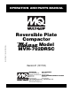
© COPYRIGHT 2003, MULTIQUIP INC. OPERATION AND PARTS MANUAL Reversible Plate Compactor Model MVH-702DRSC Revision #1 (12/17/03) MULTIQUIP INC.. PARTS DEPARTMENT: 18910 WILMINGTON AVE. 800-427-1244 CARSON, CALIFORNIA 90746 FAX: 800-672-7877 SERVICE DEPARTMENT/TECHNICAL ASSISTANCE: 310-537-3700 800-421-1244 800-478-1244 FAX: 310-537-3927 FAX: 310-631-5032 E-mail:mq@multiquip.com • www:multiquip.
PAGE 2 — MQ-MIKASA MVH-702DRSC COMPACTOR — PARTS & OPERATION MANUAL — REV.
HERE'S HOW TO GET HELP PLEASE HAVE THE MODEL AND SERIAL NUMBER ON-HAND WHEN CALLING MULTIQUIP’S MAIN PHONE NUMBERS 800-421-1244 FAX: 310-537-3927 310-537-3700 PARTS DEPARTMENT 800-427-1244 FAX: 800-672-7877 310-537-3700 FAX: 310-637-3284 MAYCO PARTS 800-306-2926 FAX: 800-672-7877 310-537-3700 FAX: 310-637-3284 SERVICE DEPARTMENT 800-478-1244 FAX: 310-537-4259 310-537-3700 MQ POWER SERVICE DEPARTMENT 800-835-2551 FAX: 310-638-8046 310-537-3700 TECHNICAL ASSISTANCE 800-478-1244 FAX: 310-631-5032 WARRANTY DEPA
TABLE OF CONTENTS MQ MIKASA MVH-702DRSCREVERSIBLE PLATE COMPACTOR PARTS ILLUSTRATIONS Nameplate and Decals....................................... 36-37 Vibrating Plate Assembly .................................. 38-39 Vibrator Assembly .............................................. 40-41 Cover Assembly ................................................. 42-45 Engine Assembly ............................................... 46-47 Hydraulic System Assembly ............................... 48-51 Electric Device..
PARTS ORDERING PROCEDURES When ordering parts, please supply the following information: ❒ ❒ ❒ ❒ ❒ ❒ ❒ Dealer account number Dealer name and address Shipping address (if different than billing address) Return fax number Applicable model number Quantity, part number and description of each part Specify preferred method of shipment: Note: Unless otherwise indicated by customer, all ✓ FedEx or UPS Ground orders are treated as “Standard Orders”, and will ✓ FedEx or UPS Second Day or Third Day ship within 24 hou
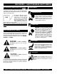
MVH-702DRSC — SAFETY MESSAGE ALERT SYMBOLS FOR YOUR SAFETY AND THE SAFETY OF OTHERS! Safety precautions should be followed at all times when operating this equipment. Failure to read and understand the Safety Messages and Operating Instructions could result in injury to yourself and others. This Owner's Manual has been developed to provide complete instructions for the safe and NOTE efficient operation of the Multiquip Model MVH-702DRSC Reversible Plate Compactor.
MVH-702DRSC — SAFETY MESSAGE ALERT SYMBOLS Accidental Starting Respiratory Hazard ALWAYS place the engine ON/OFF switch in the OFF position, when the compactor is not in use. ALWAYS wear approved respiratory protection. Equipment Damage Messages Sight and Hearing hazard ALWAYS wear approved eye and hearing protection. Other important messages are provided throughout this manual to help prevent damage to your compactor, other property, or the surrounding environment.
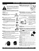
MVH-702DRSC — RULES FOR SAFE OPERATION CAUTION: Failure to follow instructions in this manual may lead to serious injury or even death! This equipment is to be operated by trained and qualified personnel only! This equipment is for industrial use only. The following safety guidelines should always be used when operating the MIKASA MVH-702DRSC Reversible Plate Compactor: GENERAL SAFETY ■ DO NOT operate or service this equipment before reading this entire manual.
MVH-702DRSC — RULES FOR SAFE OPERATION ■ ALWAYS use extreme care when operating near obstructions, on slippery surfaces, grades and side slopes. ■ When reversing, particularly on the edges and banks of ditches, as well as in front of obstacles, the operator must stay in a standing position at a safe distance from the machine. ■ When operating near any house/building or pipelines, always check the effect of machine vibration. Stop the work if necessary.
MVH-702DRSC — OPERATION AND SAFETY DECALS Figure 1 displays the operation and safety decals as they appear on the compactor. Should any of these decals become damaged or unreadable, contact the Multiquip Parts Department for a replacement set. CONTROL BOX I.
MVH-702DRSC — OPERATION AND SAFETY DECALS Figure 1 displays the operation and safety decals as they appear on the compactor. Should any of these decals become damaged or unreadable, contact the Multiquip Parts Department for a replacement set. OPERATIONAL CAUTION CAUTION 1. Read owner’s instruction manual before operating or servicing this machine. 2. The machine consists of the engine located in front, and the aluminum hydraulic oil tank in rear.
MVH-702DRSC — DIMENSIONS AND SPECIFICATIONS Figure 2. MVH-702DRSC Compactor Dimensions Table 1. MVH-702DRSC Compactor Specifications With Regular Plate Overall Length Body Dimensions Overall Width Overall Height Width Plate Size Length VPM Performance Centrifugal Force Travel Speed Model Maximum Output Engine 42.5 in. (1,080 mm) 26.8 in. (680 mm 31.5 in. (800 mm 31.3 in. (795 mm) 25.6 in. (650 mm) 31.5 in. (800 mm) 43.3 in. (1,100 mm) 1477 lbs. (670 kg.
MVH-702DRSC — FEATURES The Mikasa Model MVH-702DRSC is a Reversible Plate Compactor which operates by infra-red remote control with forward-reverse motion, steering, and stepless speed control by single-lever joystick. Features include: Machine operation is automatically stopped (vibration remains on) by releasing the single-lever joystick. Monitoring lamps for self-diagnosis are installed at the side of the machine control unit.
MVH-702DRSC — COMPACTOR COMPONENTS 11 10 Figure 3. MVH-702DRSC Compactor Components 1 7 9 6 3 4 12 5 13 14 PAGE 14 — MQ-MIKASA MVH-702DRSC COMPACTOR — PARTS & OPERATION MANUAL — REV.
MVH-702DRSC — COMPACTOR COMPONENTS Figure 3 illustrates the location of the major components for the MVH-702DRSC Reversible Plate Compactor. The function of each component is described below: 1. Monitoring Lights – Indicates if there is any failure in the machine. There are four monitoring lights: Receiving Failure Light Oil Pressure (Engine) Failure Light Regulator Failure Light E/G Overheat Light 2. Lifting Hook Lever – Used to lift the machine. 3.
MVH-702DRSC — REMOTE CONTROL COMPONENTS 2 1 4 10 3 5 9 8 7 6 Figure 4. MVH-702DRSC Remote Control Components PAGE 16 — MQ-MIKASA MVH-702DRSC COMPACTOR — PARTS & OPERATION MANUAL — REV.
MVH-702DRSC — REMOTE CONTROL COMPONENTS CONTROL UNIT (BODY) Figure 4 illustrates the location of the major components for the Remote Control on the body of the machine. The function of each component is described below: 1. 10. Monitoring Lamp – Depending on which numbered lamps light up, indicates the status of the machine (Figure 5). MONITOR LAMP 1 2 3 4 5 6 7 8 Receiving Failure Light 9 10 11 12 Oil Pressure (Engine) Failure Light Figure 5.
MVH-702DRSC — REMOTE CONTROL COMPONENTS 5 6 7 8 1 4 9 3 2 12 10 11 Figure 7. MVH-702DRSC Transmitter Components PAGE 18 — MQ-MIKASA MVH-702DRSC COMPACTOR — PARTS & OPERATION MANUAL — REV.
MVH-702DRSC — REMOTE CONTROL COMPONENTS TRANSMITTER Figure 7 illustrates the location of the major components of the transmitter. The function of each component is described below: 1. Joystick Lever – Controls the traveling speed and direction of the machine. 2. Main Switch/ Emergency Stop – Immediately stops the machine in an emergency. 3. Engine Switch –Starts and stops the engine. 4. Vibration Switch – Turns vibration on and off. 5. Signal Lamp – Infra-red monitoring lamp. 6.
MVH-702DRSC — BEFORE START-UP BEFORE START-UP SETTING THE OPERATIONAL CHANNEL 1. Read this manual carefully and understand all functions of the machine before start-up. 2. The engine is located on front side of the machine and the aluminum oil tank is on the rear. In cases where several machines operate in the same area, each machine should be transmitting in a different infra-red channel. Ten different channels can be set (0 to 9). See Table 2.
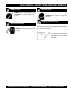
MVH-702DRSC — BATTERY CHARGING CHARGING THE BATTERY 6. Connect one end of remote cable to the receptacle. The battery can be charged in three different ways: 7. Make sure that the transmitter main switch is off. 8. Remove the cover of the remote control receptacle in the transmitter (Figure 11). 9. Connect the other end of the remote cable to the receptacle. Using the remote cable Using the AC plug-in battery charger Solar Energy Battery Charging Using Remote Cable 10.
MVH-702DRSC — OPERATION BEFORE OPERATION 1. Familiarize yourself with the operating and control elements of the machine and the working environment. This includes obstacles in the working area, bearing capacity of the ground and the necessary safety provisions. 2. Understand the geographical features and regulations of the job site. 3. Inspect caution decals and replace missing/worn-out ones. 4. Check nuts and bolts and tighten if necessary.
MVH-702DRSC — OPERATION 2. To check if restart failure is due to the reasons listed in step 3, move the transmitter engine starter switch to the on position. Check if the signal lamp. If it does not flash then reasons listed are confirmed. 5. The remote control cable may be used to restart the engine in this case. See Battery Charging Section on how to install the remote control cable. 6. Move the machine main switch to the ON position. 7.
MVH-702DRSC — LOADING AND UNLOADING GUIDELINES LIFTING 1. Use a crane or lift to load and unload the machine. A skilled crane operator is required to perform the job. 2. When lifting the machine, check for any damaged or loose bolts, lifting hooks, and shock mounts. 3. Check any damaged or loose bolts in the guard frame to avoid machine sliding off. 4. Make sure that the machine is shut off before machine is lifted. 5. Use reliable cable for lifting. 6.
MVH-702DRSC — MAINTENANCE MACHINE MAINTENANCE 1. At the end of each day’s operation, wipe off any dust from the transmitter and the receiver on the body of the machine. 2. At the end of each day’s operation, charge the transmitter battery if necessary. Refer to Table 4 in the Troubleshooting section for periodic inspection and maintenance necessary for the machine. MACHINE BATTERY MAINTENANCE 1.
MVH-702DRSC — TROUBLESHOOTING Table 3. MVH-702DRSC Oil Application Chart ITEM SERVICE CLASSIFICATION LOCATION AMBIENT TEMPERATURE (°F/°C) -22 -13 -4 5 14 32 -30 -25 -20 -15 -10 0 41 5 50 10 68 77 86 20 25 30 SAE 5W-20/5W-30 SAE 10W-30 Engine Oil Engine Oil Pan API-CD Grade SAE 20W-40 SAE 15W-40 SAE 10W-40 SAE 5W-30 Motor Oil Vibrator API-CD Grade SAE 10W-30 ISO VG32 Hydraulic Oil Hydraulic Tank ISO VG45 Hydraulic Oil ISO VG68 Table 4.
MVH-702DRSC — TROUBLESHOOTING Table 5. MVH-702DRSC Engine Inspection and Maintenance HOUR METER READING LOCATION/WORK Yearly 50 100 150 250 300 Engine Oil Replacement O O Oil Cleaner Cartridge Replacement O O Fuel Filter Cartridge Replacement 350 400 450 O O O O Sediment Removal in Fuel Tank O O Fuel Line Belt Check O O Fuel Line and Clamp Replacement O O O O O Wiring Check for Damaged and Loose Connections O O Table 6.
MVH-702DRSC — TROUBLESHOOTING TABLE 7. ENGINE TROUBLESHOOTING SYMPTOM The main switch of machine body is switched on, but no electricity is available (monitoring lamps 9, 10, and 12 are not lighted on the control unit) The main switch of the transmitter is switched on, but the engine does not start (signal lamp of transmitter does not light.) The main switch of the transmitter is switched on, but the engine does not start (signal lamp of transmitter lights but monitoring lamp no.
MVH-702DRSC — TROUBLESHOOTING TABLE 7. ENGINE TROUBLESHOOTING (continued) SYMPTOM Receiving failure light does not work but machine operates properly, Oil pressure light is on but the engine does not stop. Regulator failure light is on POSSIBLE PROBLEM SOLUTION Receiving failure light broken? Repair or replace receiving failure light. Disconnected or short-circuited wire harness? Make sure wire harness is connected properoy and correct any short circuits.
MVH-702DRSC — BLOCK DIAGRAM Figure 17. Block Diagram PAGE 30 — MQ-MIKASA MVH-702DRSC COMPACTOR — PARTS & OPERATION MANUAL — REV.
MVH-702DRSC — RECIEVER WIRING DIAGRAM Figure 18. Receiver Wiring Diagram MQ-MIKASA MVH-702DRSC COMPACTOR — PARTS & OPERATION MANUAL — REV.
MVH-702DRSC — VALVE CONTROL DIAGRAM Figure 19. Valve Control Diagram PAGE 32 — MQ-MIKASA MVH-702DRSC COMPACTOR — PARTS & OPERATION MANUAL — REV.
NOTE PAGE MQ-MIKASA MVH-702DRSC COMPACTOR — PARTS & OPERATION MANUAL — REV.
MVH-702DRSC — EXPLANATION OF CODE IN REMARKS COLUMN How to read the marks and remarks used in this parts book. Items Found In the “Remarks” Column NOTE The contents of this catalog are subject to change without notice. Serial Numbers-Where indicated, this indicates a serial number range (inclusive) where a particular part is used. Model Number-Where indicated, this shows that the corresponding part is utilized only with this specific model number or model number variant.
MVH-702DRSC — SUGGESTED SPARE PARTS MQ MIKASA MVH-702DRSC REVERSIBLE PLATE COMPACTOR 1 to 3 Units Qty. P/N 3 .......... 954001910 ........... 3 .......... 954001920 ........... 1 .......... 954001900 ........... Description OIL FILTER, HYDRAULIC SUCTION, OIL FILTER HYDRAULIC CAP, WITH BREATHER MQ-MIKASA MVH-702DRSC COMPACTOR — PARTS & OPERATION MANUAL — REV.
MVH-702DRSC COMPACTOR — NAMEPLATE AND DECALS NAMEPLATE AND DECALS PAGE 36 — MQ-MIKASA MVH-702DRSC COMPACTOR — PARTS & OPERATION MANUAL — REV.
MVH-702DRSC COMPACTOR — NAMEPLATE AND DECALS NAMEPLATE AND DECALS NO. 1 2 3 4 6 7 8 20 21 22 23 25 26 28 29 30 31 32 33 34 35 36 37 41 49 50 PART NO. 920109840 920109550 920209080 920203330 920101580 920100920 920209250 920209010 920209020 920209030 920209040 920209060 920209070 920209190 920209230 920209310 920209210 920209280 920209300 920209270 920108810 920108350 920209510 920209020 920209230 920209310 PART NAME QTY.
MVH-702DRSC COMPACTOR — VIBRATING PLATE ASSY. VIBRATING PLATE ASSY. PAGE 38 — MQ-MIKASA MVH-702DRSC COMPACTOR — PARTS & OPERATION MANUAL — REV.
MVH-702DRSC COMPACTOR — VIBRATING PLATE ASSY. VIBRATING PLATE ASSY. NO. 1 2 3 4 5 6 7 8 9 10 11 13 14 15 16 18 19 21 21 PART NO. 462116380 953405840 953402930 953400270 953405260 462340050 462340060 462340070 009120407 001221020 030210250 930413001 020318150 030218460 001221835 001222452 030224590 462116480 462116490 PART NAME QTY.
MVH-702DRSC COMPACTOR — VIBRATOR ASSY. VIBRATOR ASSY. PAGE 40 — MQ-MIKASA MVH-702DRSC COMPACTOR — PARTS & OPERATION MANUAL — REV.
MVH-702DRSC COMPACTOR — VIBRATOR ASSY. VIBRATOR ASSY. NO. 1 2 3 4 6 7 8 9 10 11 12 13 14 15 16 17 18 19 20 21 22 23 24 25 26 28 29 30 31 32 33 34 35 37 38 39 40 41 42 43 44 46 47 49 50 51 53 54 PART NO.
MVH-702DRSC COMPACTOR — COVER ASSY. COVER ASSY. PAGE 42 — MQ-MIKASA MVH-702DRSC COMPACTOR — PARTS & OPERATION MANUAL — REV.
MVH-702DRSC COMPACTOR — COVER ASSY. COVER ASSY. NO. 1 2 4 5 6 7 8 9 10 11 12 13 14 15 16 17 19 20 21 22 23 24 25 27 28 29 30 31 32 33 35 36 37 38 39 40 41 42 43 44 45 46 47 49 52 53 PART NO.
MVH-702DRSC COMPACTOR — COVER ASSY. (CONT.) COVER ASSY. PAGE 44 — MQ-MIKASA MVH-702DRSC COMPACTOR — PARTS & OPERATION MANUAL — REV.
MVH-702DRSC COMPACTOR — COVER ASSY. (CONT) COVER ASSY. NO. 54 56 57 58 59 60 61 62 64 65 66 67 68 69 70 72 73 74 75 76 77 78 79 80 81 83 84 85 86 88 89 90 91 93 94 95 96 98 99 100 101 102 103 104 PART NO.
MVH-702DRSC COMPACTOR — ENGINE ASSY. ENGINE ASSY. PAGE 46 — MQ-MIKASA MVH-702DRSC COMPACTOR — PARTS & OPERATION MANUAL — REV.
MVH-702DRSC COMPACTOR — ENGINE ASSY. ENGINE ASSY. NO. 106 107 108 109 110 111 112 113 114 115 116 117 119 120 121 122 123 124 125 126 128 129 130 131 132 133 135 136 137 138 139 140 142 144 145 146 147 PART NO.
MVH-702DRSC COMPACTOR — HYDRAULIC SYSTEM ASSY. HYDRAULIC SYSTEM ASSY. PAGE 48 — MQ-MIKASA MVH-702DRSC COMPACTOR — PARTS & OPERATION MANUAL — REV.
MVH-702DRSC COMPACTOR — HYDRAULIC SYSTEM ASSY. HYDRAULIC SYSTEM ASSY. NO. 1 2 3 4 5 7 8 9 10 11 12 13 14 15 16 18 19 20 21 22 23 25 27 28 29 30 32 33 34 36 37 38 39 40 42 43 44 45 46 47 49 PART NO.
MVH-702DRSC COMPACTOR — HYDRAULIC SYSTEM ASSY. (CONT.) HYDRAULIC SYSTEM ASSY. PAGE 50 — MQ-MIKASA MVH-702DRSC COMPACTOR — PARTS & OPERATION MANUAL — REV.
MVH-702DRSC COMPACTOR — HYDRAULIC SYSTEM ASSY. (CONT.) HYDRAULIC SYSTEM ASSY. NO. 50 51 52 53 54 55 56 57 58 59 60 62 63 64 65 66 67 68 69 70 71 72 74 76 77 79 PART NO.
MVH-702DRSC COMPACTOR — ELECTRIC DEVICE ASSY. ELECTRIC DEVICE ASSY. PAGE 52 — MQ-MIKASA MVH-702DRSC COMPACTOR — PARTS & OPERATION MANUAL — REV.
MVH-702DRSC COMPACTOR — ELECTRIC DEVICE ASSY. ELECTRIC DEVICE ASSY. NO. 1 2 3 4 5 7 8 9 10 11 12 14 15 16 18 19 20 21 23 24 25 26 28 29 31 32 33 34 37 38 39 40 41 42 43 44 45 46 47 48 49 PART NO.
MVH-702DRSC COMPACTOR — ELECTRIC DEVICE ASSY. (CONT.) ELECTRIC DEVICE ASSY. PAGE 54 — MQ-MIKASA MVH-702DRSC COMPACTOR — PARTS & OPERATION MANUAL — REV.
MVH-702DRSC COMPACTOR — ELECTRIC DEVICE ASSY. (CONT.) ELECTRIC DEVICE ASSY. NO. 51 52 53 54 55 56 57 58 59 60 61 63 64 65 66 68 69 70 PART NO. 462340480 462340510 462340470 462340460 462340500 462340490 462455100 462455090 462455110 462455080 462454890 959021821 959021814 507010110 511010040 462340670 462340540 462340450 PART NAME HARNESS (PS) HARNESS (LED, F. LAMP) HARNESS (HOUR METER) HARNESS (MAGNET VALVE) HARNESS (REGU.
TERMS AND CONDITIONS OF SALE — PARTS Effective: October 1, 2002 PAYMENT TERMS 5. Parts must be in new and resalable condition, in the original Multiquip package (if any), and with Multiquip part numbers clearly marked. 6. The following items are not returnable: Terms of payment for parts are net 10 days. FREIGHT POLICY All parts orders will be shipped collect or prepaid with the charges added to the invoice. All shipments are F.O.B. point of origin.
NOTE PAGE MQ-MIKASA MVH-702DRSC COMPACTOR — PARTS & OPERATION MANUAL — REV.
OPERATION AND PARTS MANUAL HERE'S HOW TO GET HELP PLEASE HAVE THE MODEL AND SERIAL NUMBER ON-HAND WHEN CALLING MULTIQUIP’S MAIN PHONE NUMBERS 800-421-1244 FAX: 310-537-3927 310-537-3700 PARTS DEPARTMENT 800-427-1244 FAX: 800-672-7877 310-537-3700 FAX: 310-637-3284 MAYCO PARTS 800-306-2926 FAX: 800-672-7877 310-537-3700 FAX: 310-637-3284 SERVICE DEPARTMENT 800-478-1244 FAX: 310-537-4259 310-537-3700 MQ POWER SERVICE DEPARTMENT 800-835-2551 FAX: 310-638-8046 310-537-3700 TECHNICAL ASSISTANCE 800-478-1244 FAX