OPERATION AND PARTS MANUAL MODELS MQD2H MQD3H DIAPHRAGM PUMPS (Honda GX120K1QX2 Gasoline Engine) Revision #6 (10/27/11) To find the latest revision of this publication, visit our website at: www.multiquip.com THIS MANUAL MUST ACCOMPANY THE EQUIPMENT AT ALL TIMES.
PROPOSITION 65 WARNING PAGE 2 — MQD2H/3H DIAPHRAGM PUMPS — OPERATION AND PARTS MANUAL — REV.
NOTES MQD2H/3H DIAPHRAGM PUMPS — OPERATION AND PARTS MANUAL — REV.
TABLE OF CONTENTS MQ-D2H/D3H Gasoline Powered Diaphragm Pumps HONDA GX120K1QX2 Engine Air Cleaner Assembly......................................... 46-47 Camshaft Assembly ........................................... 48-49 Carburetor Assembly ......................................... 50-51 Control Assembly ............................................... 52-53 Crankcase Cover Assembly ............................... 54-55 Crankshaft Assembly .........................................
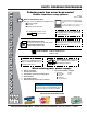
www.multiquip.com PARTS ORDERING PROCEDURES Ordering parts has never been easier! Choose from three easy options: Order via Internet (Dealers Only): Best Deal! Effective: January 1st, 2006 If you have an MQ Account, to obtain a Username and Password, E-mail us at: parts@multiquip. com. Order parts on-line using Multiquip’s SmartEquip website! ■ View Parts Diagrams ■ Order Parts ■ Print Specification Information To obtain an MQ Account, contact your District Sales Manager for more information.
SAFETY INFORMATION Do not operate or service the equipment before reading the entire manual. Safety precautions should be followed at all times when operating this equipment. Failure to read and understand the safety messages and operating instructions could result in injury to yourself and others. Potential hazards associated with the operation of this equipment will be referenced with hazard symbols which may appear throughout this manual in conjunction with safety messages.
SAFETY INFORMATION GENERAL SAFETY CAUTION NEVER operate this equipment without proper protective clothing, shatterproof glasses, respiratory protection, hearing protection, steel-toed boots and other protective devices required by the job or city and state regulations. Avoid wearing jewelry or loose fitting clothes that may snag on the controls or moving parts as this can cause serious injury. NEVER operate this equipment when not feeling well due to fatigue, illness or when under medication.
SAFETY INFORMATION PUMP SAFETY DANGER NEVER operate the equipment in an explosive atmosphere or near combustible materials. An explosion or fire could result causing severe bodily harm or even death. NEVER use pump for swimming pool dewatering applications. This can result in electrical shock or electrocution. WARNING Accidental starting can cause severe injury or death. ALWAYS place the ON/OFF switch in the OFF position. DO NOT place hands or fingers inside pump when pump is running.
SAFETY INFORMATION Power Cord/Cable Safety DANGER NEVER let power cords or cables lay in water. NEVER use damaged or worn cables or cords. Inspect for cuts in the insulation. NEVER grab or touch a live power cord or cable with wet hands. The possibility exists of electrical shock, electrocution or death. Make sure power cables are securely connected to the motor's output receptacles. Incorrect connections may cause electrical shock and damage to the motor.
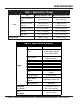
SPECIFICATIONS Table 1. Specifications (Pump) Pump Type MQ-D2H Diaphragm Pump MQ-D3H Diaphragm Pump Suction & Discharge Size 2.00 in. (50.8 mm.) 3.00 in. (76.2 mm.) Maximum Pumping Capacity 3,000 gallons/hour (11,340 liters/hour) 5,400 gallons/hour (20,456 liters/hour) Max. Solids Diameter 1-1/2 in. (38.1 mm) 1-5/8 in (41.275 mm) Max Lift 26 ft. (7.92 meters) 26 ft. (7.92 meters) Max. Head 25 ft. (7.62 meters) 25 ft. (7.62 meters) 140 lbs. (63 Kg.) 160 lbs. (72 Kg.
DIMENSIONS MQ-D2H/D3H — DIMENSIONS (PUMP) Figure 1. MQ-D2H/D3H Pump Dimensions Table 3. Dimensions MODEL A LENGTH B HEIGHT C WIDTH D DISCHARGE E SUCTION MQ-D2H 39 in. (99.06 cm.) 27.53 in. (69.93 cm.) 25.68 in. (65.23 cm.) 7.34 in. (18.64 cm.) 5.62 in. (14.27 cm.) MQ-D3H 41.5 in. (105.41 cm.) 22 in. (55.88 cm.) 30 in. (76.2 cm.) 6.2 in. (15.75 cm.) 6.3 in. (16 cm.) MQD2H/3H DIAPHRAGM PUMPS — OPERATION AND PARTS MANUAL — REV.
MQ-D2H/D3HGENERAL — GENERAL INFORMATION INFORMATION APPLICATION The MQD2H and MQD3H diaphragm pumps are designed to be used for de-watering applications. The suction and discharge ports on the MQD2H use a 2-inch diameter opening, which allows the pump to pump at rate of approximately 3,000 gallons/hour (gph) or 11,340 liters/hour (lph).
MQ-D2H/D3H — PUMPCOMPONENTS COMPONENTS Figure 2 shows a typical application using the MQD2H or MQD3H diaphragm pump. Please note that this pump is intended for the removal of clean water and water containing some debris and solids. Maximum size of solids for the MQD2H should not exceed 11/2 inches (38.1 mm) in diameter, and maximum size of solids for the MQD3H should not exceed 1-5/8 inches (41.275) in diameter. DO NOT set strainer on bottom of water bed.
BASIC ENGINE Figure 3. Engine Controls and Components INITIAL SERVICING The engine (Figure 3) must be checked for proper lubrication and filled with fuel prior to operation. Refer to the Honda manufacturers engine manual for instructions and details for operation and servicing. 1. 6. Choke Lever – Used in the starting of a cold engine, or in cold weather conditions. The choke enriches the fuel mixture. 7. Air Cleaner – Prevents dirt and other debris from entering the fuel system.
INSPECTION CAUTION - Read Manual Please read the entire maintenance section in this manual before servicing the pump. In addition for operator safety, please read all safey messages at the begining of the manual Inspection 1. Clean the pump, removing dirt and dust, particularly the engine cooling air inlet, carburetor and air cleaner. 2. Check the air filter for dirt and dust. If air filter is dirty, replace air filter with a new one as required. 3. Check carburetor for external dirt and dust.
SETUP Handle Installation WARNING - Fill Cap The MQ-D2H/D3H diaphragm pumps are completely assembled except for the steering handle. Attach the steering handle to the pump base as shown in Figure 6. DO NOT open fill cap if pump is hot! Water inside may be under pressure. Hoses and Clamps 1. Check that all hoses are securely attached to the pump. Make certain suction hose (Figure 2) does not have any air leakage. Use teflon tape or pipe dope on NPT threads. GEAR BOX HANDLE 2.
SETUP CAUTION - Strainer The strainer should be positioned so it will remain completely under water. Running the pump with the strainer above water for long periods can damage the pump. CAUTION - Flammable Fluids DO NOT pump flammable fluids, corrosive chemicals or fluids containing toxic substances. These fluids can create potentially dangerous health and environmental hazards. Contact local authorities for assistance.
MQ-D2H/D3H —OPERATION OPERATION CAUTION - Read Manual 4. Place the choke lever (Figure 12) in the "OPEN " position if starting a warm engine or the temperature is warm. DO NOT attempt to operate the pump until the Safety, General Information and Inspection sections of this manual have been read and thoroughly understood. This section is intended to assist the operator with the initial start-up of the trash pump.
MQ-D2H/D3H —OPERATION OPERATION 7. If the engine has started, slowly return the choke lever (Figure 15 ) to the “OPEN” position. If the engine has not started repeat steps 1 through 6. Stopping The Engine Normal Shutdown 1. Move the throttle lever to the IDLE position (Figure 17) and run the engine for three minutes at low speed. Figure 17. Throttle Lever (Idle) Figure 15. Choke Lever (Open) 2. After the engine cools, turn the engine ON/OFF switch to the “OFF” position (Figure 18). 8.
MAINTENANCE Pump Vacuum Test To perform the pump vacuum test do the following: 1. Start the engine as outlined in the initial start-up section, and wait for the pump to begin pumping. 2 Check and make sure that there are no air leaks between the vacuum tester (Figure 21) and the inlet port on the pump. If air leaks are present reseat vacuum tester. Flapper Valve Replacement 1. Remove the two bolts that secure the suction port chamber (Figure 20) to the pump well. Remove suction port chamber.
MAINTENANCE NOTE Pressure reading may vary depending on altitude. See Tables 4 and 5. Figure 21. Pump Vacuum Tester MQD2H/3H DIAPHRAGM PUMPS — OPERATION AND PARTS MANUAL — REV.
MAINTENANCE Rotation of Suction and Discharge Ports In some applications, it may be preferable to have suction/ discharge ports rotated 90° (Figure 22) to be in-line with the pump wheels. Perform the following procedure to rotate ports: 1. Remove the four hex head cap screws, hex nuts, flat washers and lock washers from the pump base. 2. Push pump well downwards to separate from pump base. 3. Rotate pump well 90° clockwise so that driver is positioned over top of discharge plate. 4.
MAINTENANCE Seized Plunger Diaphragm Replacement 1. Remove plunger cover as shown in step 1 of the "Seized If the plunger arm has seized, perform the following: Plunger" section. 1. Remove plunger guard (Figure 24) by turning guard hand 2. Remove handle as shown in Figure 6 of the "Handle knob counterclockwise to loosen. Installation" section. 2. Disassemble pump and clean as described in steps 1 3. Rotate pump output shaft until plunger arm is in the thru 4 in the "Stalled Pump" section. down position. 3.
MAINTENANCE Engine Maintenance Perform engine maintenance procedures as referenced by Table 7 below: Table 7. Engine Maintenance Schedule DESCRIPTION (3) OPERATION BEFORE CHECK X FIRST EVERY MONTH 3 MONTHS OR OR 10 HRS. 25 HRS. EVERY 6 MONTHS OR 50 HRS. EVERY YEAR OR 100 HRS. EVERY 2 YEARS OR 200 HRS.
MAINTENANCE Maintenance DANGER - Combustion (Fire , Explosion) Perform the engine maintenance procedures as indicated below: DAILY ■ Thoroughly remove dirt and oil from the engine and control area. Clean or replace the air cleaner elements as necessary. Check and retighten all fasteners as necessary. Check the spring box and bellows for oil leaks. Repair or replace as needed. WEEKLY ■ Remove the fuel filter cap and clean the inside of the fuel tank. ■ Remove or clean the filter at the bottom of the tank.
PREPARATION FOR LONG-TERM STORAGE Pump Storage For storage of the pump for over 30 days, the following is required: Drain the fuel tank completely. Run the engine until the fuel is completely consumed. Completely drain used oil from the engine crankcase and fill with fresh clean oil, then follow the procedures described in the engine manual for engine storage. Remove the pump cover and clean inside of pump housing. Coat inside of pump housing with a light film of oil to reduce corrosion.
TROUBLESHOOTING TABLE 8. ENGINE TROUBLESHOOTING SYMPTOM POSSIBLE PROBLEM SOLUTION Difficult to start Fuel is available but spark plug will not ignite. (Power available at high tension cable). Fuel is available but spark plug will not ignite. (Power NOT available at high tension cable). Fuel is available and spark plug ignites (compression normal). Fuel is available and spark plug ignites (compression low ). Ignition plug being bridge? Check ignition system.
TROUBLESHOOTING TABLE 8. ENGINE TROUBLESHOOTING (Continued) SYMPTOM POSSIBLE PROBLEM SOLUTION Operation not satisfactory Rotational speed fluctuates. Recoil star ter not working properly. Governor adjustment improper? Adjust governor to correct lever. Governor spring defective? Clean or replace ignition. Fuel flow erratic? Check fuel line. Air taken in through suction line? Check suction line. Dust in rotating par t? Clean recoil star ter assembly.
TROUBLESHOOTING TABLE 9. PUMP TROUBLESHOOTING (Continued) SYMPTOM POSSIBLE PROBLEM SOLUTION Incorrect engine speed speed? Increase engine speed. Piping is clogged or damaged? Clean or replace piping. Clogged pump? Clean pump well. Discharge line restricted or undersize? Flush out piping or replace. Collapsible disc hose? Replace with rgid or noncollapsible hose. Too many hose bends? Straighten hose. Hose lines too long? Shor ten hose lines. Faulty suction piping? Replace piping.
EXPLANATION OF CODE IN REMARKS COLUMN The following section explains the different symbols and remarks used in the Parts section of this manual. Use the help numbers found on the back page of the manual if there are any questions. NOTICE The contents and part numbers listed in the parts section are subject to change without notice. Multiquip does not guarantee the availability of the parts listed. SAMPLE PARTS LIST NO. 1 2% 2% 3 4 PART NO. PART NAME QTY. REMARKS 12345 BOLT......................1 .....
SUGGESTED SPARE PARTS MQ-D2H/D3H DIAPHRAGM PUMP 1 TO 3 UNITS WITH HONDA GX120K1QX2 ENGINE Qty. P/N Description 3 ............ 17210ZE0505 ....... ELEMENT AIR CLEANER DUAL 3 ............ 9807955846 .......... SPARK PLUG 1 ............ 17620ZH7023 ....... CAP, FUEL WITH GASKET 1 ............ 28462ZH8003 ....... ROPE STARTER 1 ............ 336030000 ............ DIAPHRAGM 2-INCH 1 ............ 213200000 ............ DIAPHRAGM 3-INCH 2 ............ 336007090 ............ FLAP VALVE 2-INCH 2 ............
NAME PLATE AND MQ-D2H/3H — NAMEPLATE ANDDECALS DECALS ASSY. ASSY. NAMEPLATE AND DECALS ASSY. PAGE 32 — MQD2H/3H DIAPHRAGM PUMPS — OPERATION AND PARTS MANUAL — REV.
NAME PLATE AND MQ-D2H/3H — NAMEPLATE ANDDECALS DECALS ASSY. ASSY. NAMEPLATE AND DECALS ASSY. NO. PART NO. PART NAME QTY. REMARKS 1 DCL1261 DECAL, GREASE MONTHLY 1 2 DECAL, NAMEPLATE .................................................. 1 .......... CONTACT MQ PARTS DEPT 3 205901900 DECAL, CAUTION, KEEP GUARDS IN PLACE 1 4 335425200 DECAL, CAUTION, AVOID EQUIPMENT DAMAGE 1 5 205200200 DECAL, CAUTION, AVOID PERSONAL INJURY 1 6 512910 DECAL, MQ LOGO 1 MQD2H/3H DIAPHRAGM PUMPS — OPERATION AND PARTS MANUAL — REV.
MQD2H — WATERBOX AND FLAP VALVE ASSY. WATERBOX AND FLAP VALVE ASSY. (2-INCH) PAGE 34 — MQD2H/3H DIAPHRAGM PUMPS — OPERATION AND PARTS MANUAL — REV.
MQD2H — WATERBOX AND FLAP VALVE ASSY. WATERBOX AND FLAP VALVE ASSY. (2-INCH) NO. PART NO.
MQD2H —PUMP ASSY. PUMP ASSY. (2-INCH) PAGE 36 — MQD2H/3H DIAPHRAGM PUMPS — OPERATION AND PARTS MANUAL — REV.
MQD2H —PUMP ASSY. PUMP ASSY. (2-INCH) NO. PART NO.
MQD2H —HANDLE, ENGINE, AND WHEEL ASSY. HANDLE, ENGINE AND WHEEL ASSY. (2-INCH) 7 8 9 6 1 2 20 5 3 11 13 10 12 15 14 16 17 18 19 PAGE 38 — MQD2H/3H DIAPHRAGM PUMPS — OPERATION AND PARTS MANUAL — REV.
MQD2H —HANDLE, ENGINE, AND WHEEL ASSY. HANDLE, ENGINE AND WHEEL ASSY. (2-INCH) NO. PART NO. PART NAME QTY. REMARKS 1 335411690 HANDLE .................................................................... 1 ...... REPLACES 215200000 2 13178 BOLT 1/2"-13 X 2-1/4" ............................................... 2 ...... REPLACES 176601300 & 175900100 3 0447 FLAT WASHER 1/2" ................................................... 2 ......
MQD3H —WATERBOX AND FLAP VALVE ASSY. WATERBOX AND FLAP VALVE ASSY. (3-INCH) PAGE 40 — MQD2H/3H DIAPHRAGM PUMPS — OPERATION AND PARTS MANUAL — REV.
MQD3H —WATERBOX AND FLAP VALVE ASSY. WATERBOX AND FLAP VALVE ASSY. (3-INCH) NO. PART NO.
MQD3H — PUMP ASSY. PUMP ASSY. (3-INCH) 8 5 2 3 2 37 4 40 3 7 6 1 27 OLD STYLE PLUNGER ASSY. 35 29 13 27 21 22 38 31 26 24 44 33 34 28 1 28 30 32 25 12 4 18 NEW STYLE PLUNGER ASSY. 10 11 12 17 19 16 15 13 39 2 9 20 14 40 43 42 NOTES: 41 1 TORQUE TO 7-8 FT. LBS. 2 TORQUE TO 55-60 FT. LBS. 3 OLD STYLE PLUNGER ARM, ITEM 3, NO LONGER AVAILABLE. IF REPLACEMENT IS REQUIRED, ORDER NEW STYLE PLUNGER ASSY. PARTS.
MQD3H — PUMP ASSY. PUMP ASSY. (3-INCH) NO. PART NO.
MQD3H——HANDLE, HANDLE, ENGINE, AND WHEEL ASSY. MQ-D3H ENGINE AND WHEEL ASSY. (3-INCH) HANDLE, ENGINE AND WHEEL ASSY. (3-INCH) 7 8 9 6 1 20 2 3 5 11 13 10 12 15 14 16 17 18 19 PAGE 44 — MQD2H/3H DIAPHRAGM PUMPS — OPERATION AND PARTS MANUAL — REV.
MQD3H——HANDLE, HANDLE, ENGINE, AND WHEEL ASSY. MQ-D2H/D3H ENGINE AND WHEEL ASSY. (3-INCH) HANDLE, ENGINE AND WHEEL ASSY. (3-INCH) NO. PART NO. PART NAME QTY. REMARKS 1 335411690 HANDLE .................................................................... 1 ...... REPLACES 215200000 2 13178 BOLT 1/2"-13 X 2-1/4" ............................................... 2 ...... REPLACES 176601600 3 0447 FLAT WASHER 1/2" ................................................... 2 ......
HONDA GX120K1QX2 ENGINE — AIR CLEANER ASSY. AIR CLEANER ASSY. PAGE 46 — MQD2H/3H DIAPHRAGM PUMPS — OPERATION AND PARTS MANUAL — REV.
HONDA GX120K1QX2 ENGINE — AIR CLEANER ASSY. AIR CLEANER ASSY. NO. 1 2 3 * 4 5 * 7# 8# 9 12 13 14 PART NO. 16271ZE1000 17210ZE0505 17218ZE0505 17230ZE0820 17232891000 17238ZE0010 17239ZE1000 17410ZE0030 90325044000 957010602000 9405006000 PART NAME QTY. REMARKS GASKET, ELBOW 1 ELEMENT, AIR CLEANER (DUAL) ................... 1............. INCLUDES ITEMS W/ * FILTER, OUTER 1 COVER, AIR CLEANER (DUAL) 1 GROMMET, AIR CLEANER 1 COLLAR, AIR CLEANER 2 COLLAR B, AIR CLEANER 1 ELBOW, AIR CLEANER ..................
HONDA GX120K1QX2 ENGINE — CAMSHAFT ASSY. CAMSHAFT ASSY. PAGE 48 — MQD2H/3H DIAPHRAGM PUMPS — OPERATION AND PARTS MANUAL — REV.
HONDA GX120K1QX2 ENGINE — CAMSHAFT ASSY. CAMSHAFT ASSY. NO. 1 2 3 4 5 6 * 7 8 9 10 11 12 13 14 15 PART NO. 14100ZE0812 14410ZE0010 14431ZE1000 14441ZE1010 14451ZE1013 14568ZE1000 14711ZF0010 14721ZF0000 14751ZF1000 14771ZE1000 14773ZE1000 14781ZE1000 14791ZE0010 90012ZE0010 90206ZE1000 PART NAME QTY. REMARKS CAMSHAFT ASSEMBLY .................................. 1.............INCLUDES ITEMS W/ * ROD, PUSH 2 ARM, VALVE ROCKER 2 LIFTER, VALVE 2 PIVOT, ROCKER ARM 2 SPRING, WEIGHT RETURN 1 VALVE, IN.
HONDA GX120K1QX2 ENGINE — CARBURETOR ASSY. CARBURETOR ASSY. PAGE 50 — MQD2H/3H DIAPHRAGM PUMPS — OPERATION AND PARTS MANUAL — REV.
HONDA GX120K1QX2 ENGINE — CARBURETOR ASSY. CARBURETOR ASSY. NO. 1 * 2 * 3 * 4 * 5 * 6 * 7 * 8 * 9 10 * 11 * 12 * 13 14 15 16 17 18 * 19 * 20 * 21 * 22 * 23 * 24# 25 25 25 * 26 * PART NO.
HONDA GX120K1QX2 ENGINE — CONTROL ASSY. CONTROL ASSY. PAGE 52 — MQD2H/3H DIAPHRAGM PUMPS — OPERATION AND PARTS MANUAL — REV.
HONDA GX120K1QX2 ENGINE — CONTROL ASSY. CONTROL ASSY. NO. 3 4 5 6 7 8# 9# 10# 11# 12# 14# 15# 16# 18 19 20 21# 24# 25# 26 PART NO. 16500ZH7820 16551ZE0010 16555ZE0000 16561ZE0020 16562ZE0020 16571ZH7000 16574ZE1000 16575ZH8000 16576891000 16578ZE1000 16580ZH7810 16584883300 16592ZE1810 90013883000 90015ZE5010 90022888010 90114SA0000 93500050250H 93500050160A 9405006000 PART NAME QTY. REMARKS CONTROL ASSEMBLY (REMOTE) ........... 1 ............
HONDA GX120K1QX2 ENGINE — CRANKCASE COVER ASSY. CRANKCASE COVER ASSY. PAGE 54 — MQD2H/3H DIAPHRAGM PUMPS — OPERATION AND PARTS MANUAL — REV.
HONDA GX120K1QX2 ENGINE — CRANKCASE COVER ASSY. CRANKCASE COVER ASSY. NO. 1 2 3 4 7# 8+ 9 10 * 11 * 12 PART NO. 11300ZE0640 11381ZH7800 15600ZE1003 15600ZG4003 15625ZE1003 15625ZE1003 90015883000 91001878003 91203ZE0003 9430108140 PART NAME QTY. REMARKS COVER ASSEMBLY, CRANKCASE (W- TYPE)....... 1 .............. INCLUDES ITEMS W/ * GASKET, CASE COVER 1 CAP ASSEMBLY, OIL FILLER ................................ 1 .............. INCLUDES ITEMS W/# CAP ASSEMBLY, OIL FILLER ................................ 1 .
HONDA GX120K1QX2 ENGINE CRANKSHAFT HONDA GX120K1QX2 ENGINE— — CRANKSHAFT ASSY. ASSY. CRANKSHAFT ASSY. PAGE 56 — MQD2H/3H DIAPHRAGM PUMPS — OPERATION AND PARTS MANUAL — REV.
HONDA GX120K1QX2 ENGINE CRANKSHAFT HONDA GX120K1QX2 ENGINE—— CRANKSHAFT ASSY. ASSY. CRANKSHAFT ASSY. NO. 1 2 PART NO. 13310ZE0601 90745ZE1600 PART NAME CRANKSHAFT, H-TYPE KEY 4.78 X4.78X38 QTY. 1 1 REMARKS MQD2H/3H DIAPHRAGM PUMPS — OPERATION AND PARTS MANUAL — REV.
HONDA GX120K1QX2 ENGINE — CYLINDER BARREL ASSY. CYLINDER BARREL ASSY. PAGE 58 — MQD2H/3H DIAPHRAGM PUMPS — OPERATION AND PARTS MANUAL — REV.
HONDA GX120K1QX2 ENGINE — CYLINDER BARREL ASSY. CYLINDER BARREL ASSY. NO. 2 3 4 5# 6# 7# 8 9 10 11 12 13 14 * 15 * 16 17 18 19 20 PART NO. 120A0ZH7810 15510ZE1033 16510ZE1000 16511ZE1000 16512ZE1000 16513ZE1000 16531ZE1000 16541ZE1000 90131ZE1000 90451ZE1000 90601ZE1000 90602ZE1000 91001878003 91202ZE6003 91353671003 9405010000 9410106800 9425108000 957010601200 PART NAME QTY. REMARKS CYLINDER ASSEMBLY (OIL ALERT) ........1 ............ INCLUDES ITEMS W/ * SWITCH ASSEMBLY, OIL LEVEL 1 GOVERNOR ASSEMBLLY .
GX120K1QX2 ENGINE CYLINDERHEAD HEAD ASSY. ASSY. HONDAHONDA GX120K1QX2 ENGINE —— CYLINDER CYLINDER HEAD ASSY. PAGE 60 — MQD2H/3H DIAPHRAGM PUMPS — OPERATION AND PARTS MANUAL — REV.
HONDA HONDA GX120K1QX2 ENGINE — CYLINDER GX120K1QX2 ENGINE — CYLINDERHEAD HEAD ASSY. ASSY. CYLINDER HEAD ASSY. NO. 1 2 * 3 * 4 + * 5 6 6 7 8 9 10 11 12 14 15 PART NO. 12210ZH7000 12204ZE1306 12205ZE1315 12216ZE5300 12251ZH7800 12310ZE1000 12310ZE1010 12391ZE1000 15721ZH8000 90013883000 90043ZE1020 90047ZE1000 9430110160 957230805500 9807955846 PART NAME QTY. REMARKS CYLINDER HEAD .................................................. 1 .............. INCLUDES ITEMS W/ * GUIDE, VALVE (OS) OPTIONAL 1 GUIDE, EX.
HONDA GX120K1QX2 ENGINE —— FAN HONDA GX120K1QX2 ENGINE FANCOVER COVER ASSY. ASSY. FAN COVER ASSY. PAGE 62 — MQD2H/3H DIAPHRAGM PUMPS — OPERATION AND PARTS MANUAL — REV.
HONDA GX120K1QX2 ENGINE FAN HONDA GX120K1QX2 ENGINE—— FANCOVER COVER ASSY. ASSY. FAN COVER ASSY. NO. 1 2 3 4 5 6 7 7 8 9 10 11 13 PART NO.
HONDA GX120K1QX2 ENGINE—— FLYWHEEL ASSY. ASSY. HONDA GX120K1QX2 ENGINE FLYWHEEL FLYWHEEL ASSY. PAGE 64 — MQD2H/3H DIAPHRAGM PUMPS — OPERATION AND PARTS MANUAL — REV.
HONDA GX120K1QX2 ENGINE—— FLYWHEEL ASSY. ASSY. HONDA GX120K1QX2 ENGINE FLYWHEEL FLYWHEEL ASSY. NO. 1 2 4 5 7 PART NO. 13331357000 19511ZE0000 28451ZH8003 31100ZE0010 90201878003 PART NAME KEY, SPECIAL WOODRUFF 25X18 FAN, COOLING PULLEY, STARTER FLYWHEEL NUT, SPECIAL 14MM QTY. 1 1 1 1 1 REMARKS MQD2H/3H DIAPHRAGM PUMPS — OPERATION AND PARTS MANUAL — REV.
HONDA GX120K1QX2 ENGINE— — FUELTANK TANK ASSY. ASSY. HONDA GX120K1QX2 ENGINE FUEL FUEL TANK ASSY. PAGE 66 — MQD2H/3H DIAPHRAGM PUMPS — OPERATION AND PARTS MANUAL — REV.
HONDA GX120K1QX2 ENGINE— — FUELTANK TANK ASSY. ASSY. HONDA GX120K1QX2 ENGINE FUEL FUEL TANK ASSY. NO. 1 2 3 5 6 * 11 12 13 14 15 PART NO. 16854ZH8000 16955ZE1000 17510ZE0020ZD 17620ZH7023 17631ZH7003 91353671003 9405006000 950014500360M 9500202080 90004ZH7003 PART NAME QTY. REMARKS RUBBER, SUPPORTER 107MM 1 JOINT, FUEL TANK 1 TANK, FUEL *NH1* (BLACK) 1 CAP, FUEL FILLER ..................................... 1 .......... INCLUDES ITEMS W/ * GASKET, FUEL FILLER CAP 1 O- RING 13.5X1.
HONDAHONDA GX120K1QX2 ENGINE — IGNITION GX120K1QX2 ENGINE — IGNITIONCOIL COIL ASSY. ASSY. IGNITION COIL ASSY. PAGE 68 — MQD2H/3H DIAPHRAGM PUMPS — OPERATION AND PARTS MANUAL — REV.
HONDAHONDA GX120K1QX2 ENGINE — IGNITION GX120K1QX2 ENGINE — IGNITIONCOIL COIL ASSY. ASSY. IGNITION COIL ASSY. NO. 1 2 8 PART NO. 30500ZE1033 30700ZE1013 90121952000 PART NAME COIL ASSEMBLY, IGNITION CAP ASSEMBLY, NOISE SUPPRESSOR BOLT, FLANGE 6X25 QTY. 1 1 2 REMARKS MQD2H/3H DIAPHRAGM PUMPS — OPERATION AND PARTS MANUAL — REV.
HONDA GX120K1QX2 ENGINE HONDA GX120K1QX2 ENGINE——MUFFLER MUFFLER ASSY. ASSY. MUFFLER ASSY. PAGE 70 — MQD2H/3H DIAPHRAGM PUMPS — OPERATION AND PARTS MANUAL — REV.
HONDA GX120K1QX2 ENGINE HONDA GX120K1QX2 ENGINE——MUFFLER MUFFLER ASSY. ASSY. MUFFLER ASSY. NO. 1 3 7 10 13 PART NO. 18310ZF1000 18320ZF1H01 18381ZH8800 90050ZE1000 94001080000S PART NAME MUFFLER PROTECTOR, MUFFLER GASKET, MUFFLER SCREW, TAPPING 5X8 NUT, HEX. 8MM QTY. 1 1 1 4 2 REMARKS MQD2H/3H DIAPHRAGM PUMPS — OPERATION AND PARTS MANUAL — REV.
HONDA GX120K1QX2 ENGINE — PISTON ASSY. PISTON ASSY. PAGE 72 — MQD2H/3H DIAPHRAGM PUMPS — OPERATION AND PARTS MANUAL — REV.
HONDA GX120K1QX2 ENGINE — PISTON ASSY. PISTON ASSY. NO. 1 1 1 1 2 2 2 2 3 4 4 5 * 6 PART NO. 13010ZK7V01 13011ZE6013 13012ZK7V01 13013ZK7V01 13101ZH7000 13102ZH7000 13103ZH7000 13104ZH7000 13111ZE0000 132A0ZE0000 13200ZE0000 90001ZE1000 90551ZE0000 PART NAME QTY. REMARKS RING SET, PISTON (STANDARD) 1 RING SET, PISTON (OS 0.25), OPTIONAL 1 RING SET, PISTON (OS 0.50) , OPTIONAL 1 RING SET, PISTON (OS 0.75), OPTIONAL 1 PISTON, STANDARD 1 PISTON, OS 0.25 1 PISTON, OS 0.50 1 PISTON, 0.
HONDA GX120K1QX2 ENGINE — RECOIL STARTER ASSY. RECOIL STARTER ASSY. PAGE 74 — MQD2H/3H DIAPHRAGM PUMPS — OPERATION AND PARTS MANUAL — REV.
HONDA GX120K1QX2 ENGINE — RECOIL STARTER ASSY. RECOIL STARTER ASSY. NO. 1 2 * 3 * 4 * 5 * 6 * 7 * 8 * 9 * 10 * 11 * 12 PART NO. 28400ZH8013ZB 28410ZH8003ZB 28420ZH8013 28422ZH8013 28433ZH8003 28441ZH8003 28442ZH8003 28443ZH8003 28461ZH8003 28462ZH8003 90003ZH8003 9008ZE2003 PART NAME QTY. REMARKS STARTER ASSY., RECOIL *NH1* (BLACK) .......... 1 ..............
HONDA GX120K1QX2 ENGINE GASKET HONDA GX120K1QX2 ENGINE— — GASKETKIT KIT ASSY. ASSY. GASKET KIT ASSY. PAGE 76 — MQD2H/3H DIAPHRAGM PUMPS — OPERATION AND PARTS MANUAL — REV.
HONDA GX120K1QX2 ENGINE GASKET HONDA GX120K1QX2 ENGINE— — GASKETKIT KIT ASSY. ASSY. GASKET KIT ASSY. NO. 2 3 * 4 * 5 * 6 * 7 * 8 * PART NO. 06111ZH7405 11381ZH7800 12251ZH7800 12391ZE1000 16212ZH7800 16221ZH8801 18381ZH8800 PART NAME QTY. REMARKS GASKET KIT ......................................................... 1 ..............
HONDA GX120K1QX2 ENGINE — LABELS ASSY. LABELS ASSY. PAGE 78 — MQD2H/3H DIAPHRAGM PUMPS — OPERATION AND PARTS MANUAL — REV.
HONDA GX120K1QX2 ENGINE — LABELS ASSY. LABELS ASSY. NO. 1 3 4 6 PART NO. 87521ZH7020 87522ZH9000 87528ZE1810 87532ZH8810 PART NAME EMBLEM LABEL, CAUTION MARK, CHOKE MARK, OIL ALERT (E) QTY. 1 1 1 1 REMARKS MQD2H/3H DIAPHRAGM PUMPS — OPERATION AND PARTS MANUAL — REV.
TERMS AND CONDITION OF SALE — PARTS PAYMENT TERMS 5. Parts must be in new and resalable condition, in the original Multiquip package (if any), and with Multiquip part numbers clearly marked. 6. The following items are not returnable: Multiquip reserves the right to quote and sell direct to Government agencies, and to Original Equipment Manufacturer accounts who use our products as integral parts of their own products. a. SPECIAL EXPEDITING SERVICE Terms of payment for parts are net 30 days.
NOTES MQD2H/3H DIAPHRAGM PUMPS — OPERATION AND PARTS MANUAL — REV.
OPERATION AND PARTS MANUAL HERE’S HOW TO GET HELP PLEASE HAVE THE MODEL AND SERIAL NUMBER ON-HAND WHEN CALLING UNITED STATES Multiquip Corporate Office 18910 Wilmington Ave. Carson, CA 90746 Contact: mq@multiquip.com MQ Parts Department Tel. (800) 421-1244 Fax (800) 537-3927 Mayco Parts 800-427-1244 310-537-3700 Fax: 800-672-7877 Fax: 310-637-3284 Warranty Department 800-306-2926 310-537-3700 Fax: 800-672-7877 Fax: 310-637-3284 Service Department 800-421-1244, Ext. 279 310-537-3700, Ext.