OPERATION AND PARTS MANUAL MODELS MQD2H MQD3H DIAPHRAGM PUMPS (Honda GX120UT1QX2 Gasoline Engine) Revision #7 (05/24/13) To find the latest revision of this publication, visit our website at: www.multiquip.com THIS MANUAL MUST ACCOMPANY THE EQUIPMENT AT ALL TIMES.
PROPOSITION 65 WARNING PAGE 2 — MQD2H/3H DIAPHRAGM PUMPS — OPERATION AND PARTS MANUAL — REV.
NOTES MQD2H/3H DIAPHRAGM PUMPS — OPERATION AND PARTS MANUAL — REV.
TABLE OF CONTENTS MQD2H/D3H Gasoline Powered Diaphragm Pumps Proposition 65 Warning ............................................. 2 Table of Contents ...................................................... 4 Parts Ordering Procedures ....................................... 5 Safety Information .................................................. 6-9 Specifications ...........................................................10 Dimensions ..............................................................
www.multiquip.com PARTS ORDERING PROCEDURES Ordering parts has never been easier! Choose from three easy options: Order via Internet (Dealers Only): Best Deal! Effective: January 1st, 2006 If you have an MQ Account, to obtain a Username and Password, E-mail us at: parts@multiquip. com. Order parts on-line using Multiquip’s SmartEquip website! ■ View Parts Diagrams ■ Order Parts ■ Print Specification Information To obtain an MQ Account, contact your District Sales Manager for more information.
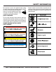
SAFETY INFORMATION Do not operate or service the equipment before reading the entire manual. Safety precautions should be followed at all times when operating this equipment. Failure to read and understand the safety messages and operating instructions could result in injury to yourself and others. Potential hazards associated with the operation of this equipment will be referenced with hazard symbols which may appear throughout this manual in conjunction with safety messages.
SAFETY INFORMATION GENERAL SAFETY CAUTION NEVER operate this equipment without proper protective clothing, shatterproof glasses, respiratory protection, hearing protection, steel-toed boots and other protective devices required by the job or city and state regulations. Avoid wearing jewelry or loose fitting clothes that may snag on the controls or moving parts as this can cause serious injury. NEVER operate this equipment when not feeling well due to fatigue, illness or when under medication.
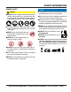
SAFETY INFORMATION PUMP SAFETY DANGER NEVER operate the equipment in an explosive atmosphere or near combustible materials. An explosion or fire could result causing severe bodily harm or even death. WARNING ALWAYS flush pump (clean) after use when pumping water concentrated with heavy debris. It is very important to always flush the pump before turning it off to prevent clogging. Fix damage to machine and replace any broken parts immediately. ALWAYS store equipment properly when it is not being used.
NOTES MQD2H/3H DIAPHRAGM PUMPS — OPERATION AND PARTS MANUAL — REV.
SPECIFICATIONS Table 1. Specifications (Pump) Pump Type MMQD2H Q-D2H Diaphragm DiaphragmPump Pump MMQD3H Q-D3H DDiaphragm iaphragm Pump Pump Suction & Discharge Size 2.00 in. (50.8 mm.) 3.00 in. (76.2 mm.) Maximum Pumping Capacity 3,000 gallons/hour (11,340 liters/hour) 5,400 gallons/hour (20,456 liters/hour) Max. Solids Diameter 1-1/2 in. (38.1 mm) 1-5/8 in (41.275 mm) Max Lift 26 ft. (7.92 meters) 26 ft. (7.92 meters) Max. Head 25 ft. (7.62 meters) 25 ft. (7.62 meters) 140 lbs.
DIMENSIONS MQ-D2H/D3H — DIMENSIONS (PUMP) Figure 1. MQD2H/D3H Pump Dimensions Table 3. Dimensions MODEL A LENGTH B HEIGHT C WIDTH D DISCHARGE E SUCTION MQ-D2H MQD2H 39 in. (99.06 cm.) 27.53 in. (69.93 cm.) 25.68 in. (65.23 cm.) 7.34 in. (18.64 cm.) 5.62 in. (14.27 cm.) MQD3H M Q-D3H 41.5 in. (105.41 cm.) 22 in. (55.88 cm.) 30 in. (76.2 cm.) 6.2 in. (15.75 cm.) 6.3 in. (16 cm.) MQD2H/3H DIAPHRAGM PUMPS — OPERATION AND PARTS MANUAL — REV.
MQ-D2H/D3HGENERAL — GENERAL INFORMATION INFORMATION APPLICATION The MQD2H and MQD3H diaphragm pumps are designed to be used for de-watering applications. The suction and discharge ports on the MQD2H use a 2-inch diameter opening, which allows the pump to pump at rate of approximately 3,000 gallons/hour (gph) or 11,340 liters/hour (lph).
MQ-D2H/D3H — PUMPCOMPONENTS COMPONENTS Figure 2 shows a typical application using the MQD2H or MQD3H diaphragm pump. Please note that this pump is intended for the removal of clean water and water containing some debris and solids. Maximum size of solids for the MQD2H should not exceed 11/2 inches (38.1 mm) in diameter, and maximum size of solids for the MQD3H should not exceed 1-5/8 inches (41.275) in diameter. DO NOT set strainer on bottom of water bed.
BASIC ENGINE Figure 3. Engine Controls and Components INITIAL SERVICING The engine (Figure 3) must be checked for proper lubrication and filled with fuel prior to operation. Refer to the Honda manufacturers engine manual for instructions and details for operation and servicing. 1. 6. Choke Lever – Used in the starting of a cold engine, or in cold weather conditions. The choke enriches the fuel mixture. 7. Air Cleaner – Prevents dirt and other debris from entering the fuel system.
INSPECTION UPPER LIMIT CAUTION - Read Manual Please read the entire maintenance section in this manual before servicing the pump. In addition for operator safety, please read all safey messages at the begining of the manual LOWER LIMIT Inspection Figure 5. Engine Oil Dipstick (Oil Level) 1. Clean the pump, removing dirt and dust, particularly the engine cooling air inlet, carburetor and air cleaner. 2. Check the air filter for dirt and dust.
SETUP Handle Installation Before Starting CAUTION - Handle Mounting Failure to follow instructions and properly install handle, mounting screws with washers, and torque mounting screws, will result in damage or premature failure to gearbox, base or other pump components. The MQD2H/D3H diaphragm pumps are completely assembled except for the steering handle. Attach the steering handle to the pump base as referenced below: 1.
SETUP CAUTION - Strainer The strainer should be positioned so it will remain completely under water. Running the pump with the strainer above water for long periods can damage the pump. CAUTION - Flammable Fluids DO NOT pump flammable fluids, corrosive chemicals or fluids containing toxic substances. These fluids can create potentially dangerous health and environmental hazards. Contact local authorities for assistance.
MQ-D2H/D3H —OPERATION OPERATION CAUTION - Read Manual DO NOT attempt to operate the pump until the Safety, General Information and Inspection sections of this manual have been read and thoroughly understood. CAUTION - General Safety Precautions NEVER operate the pump in a confined area or enclosed area structure that does not provide ample free flow of air. Figure 11. Engine Choke Lever (CLOSED) 4.
MQ-D2H/D3H —OPERATION OPERATION 7. If the engine has started, slowly return the choke lever (Figure 15 ) to the “OPEN” position. If the engine has not started repeat steps 1 through 6. Stopping The Engine Normal Shutdown 1. Move the throttle lever to the IDLE position (Figure 17) and run the engine for three minutes at low speed. Figure 17. Throttle Lever (Idle) Figure 15. Choke Lever (Open) 2. After the engine cools, turn the engine ON/OFF switch to the “OFF” position (Figure 18). 8.
MAINTENANCE Pump Vacuum Test To perform the pump vacuum test do the following: 1. Start the engine as outlined in the initial start-up section, and wait for the pump to begin pumping. 2 Flapper Valve Replacement 1. Remove the two bolts that secure the suction port chamber (Figure 20) to the pump well. Remove suction port chamber. Replace valves as required and reassemble. Check and make sure that there are no air leaks between the vacuum tester (Figure 21) and the inlet port on the pump.
MAINTENANCE NOTE Pressure reading may vary depending on altitude. See Tables 4 and 5. Figure 21. Pump Vacuum Tester MQD2H/3H DIAPHRAGM PUMPS — OPERATION AND PARTS MANUAL — REV.
MAINTENANCE Rotation of Suction and Discharge Ports In some applications, it may be preferable to have suction/ discharge ports rotated 90° (Figure 22) to be in-line with the pump wheels. Perform the following procedure to rotate ports: 1. Remove the four hex head cap screws, hex nuts, flat washers and lock washers from the pump base. 2. Push pump well downwards to separate from pump base. 3. Rotate pump well 90° clockwise so that driver is positioned over top of discharge plate. 4.
MAINTENANCE Seized Plunger Diaphragm Replacement 1. Remove plunger cover as shown in step 1 of the "Seized If the plunger arm has seized, perform the following: Plunger" section. 1. Remove plunger guard (Figure 24) by removing slotted 2. Remove handle as shown in Figure 6 of the "Handle screw (2). Installation" section. 2. Disassemble pump and clean as described in steps 1 3. Rotate pump output shaft until plunger arm is in the thru 4 in the "Stalled Pump" section. down position. 3.
MAINTENANCE Engine Maintenance Perform engine maintenance procedures as referenced by Table 7 below: Table 7. Engine Maintenance Schedule DESCRIPTION (3) OPERATION BEFORE CHECK X FIRST EVERY MONTH 3 MONTHS OR OR 10 HRS. 25 HRS. EVERY 6 MONTHS OR 50 HRS. EVERY YEAR OR 100 HRS. EVERY 2 YEARS OR 200 HRS.
MAINTENANCE Maintenance DANGER - Combustion (Fire , Explosion) Perform the engine maintenance procedures as indicated below: DAILY ■ Thoroughly remove dirt and oil from the engine and control area. Clean or replace the air cleaner elements as necessary. Check and retighten all fasteners as necessary. Check the spring box and bellows for oil leaks. Repair or replace as needed. WEEKLY ■ Remove the fuel filter cap and clean the inside of the fuel tank. ■ Remove or clean the filter at the bottom of the tank.
PREPARATION FOR LONG-TERM STORAGE Pump Storage For storage of the pump for over 30 days, the following is required: Drain the fuel tank completely. Run the engine until the fuel is completely consumed. Completely drain used oil from the engine crankcase and fill with fresh clean oil, then follow the procedures described in the engine manual for engine storage. Remove the pump cover and clean inside of pump housing. Coat inside of pump housing with a light film of oil to reduce corrosion.
TROUBLESHOOTING TABLE 8. ENGINE TROUBLESHOOTING SYMPTOM POSSIBLE PROBLEM SOLUTION Difficult to start Fuel is available but spark plug will not ignite. (Power available at high tension cable). Fuel is available but spark plug will not ignite. (Power NOT available at high tension cable). Fuel is available and spark plug ignites (compression normal). Fuel is available and spark plug ignites (compression low ). Ignition plug being bridge? Check ignition system.
TROUBLESHOOTING TABLE 8. ENGINE TROUBLESHOOTING (Continued) SYMPTOM POSSIBLE PROBLEM SOLUTION Operation not satisfactory Rotational speed fluctuates. Recoil star ter not working properly. Governor adjustment improper? Adjust governor to correct lever. Governor spring defective? Clean or replace ignition. Fuel flow erratic? Check fuel line. Air taken in through suction line? Check suction line. Dust in rotating par t? Clean recoil star ter assembly.
TROUBLESHOOTING TABLE 9. PUMP TROUBLESHOOTING (Continued) SYMPTOM POSSIBLE PROBLEM SOLUTION Incorrect engine speed speed? Increase engine speed. Piping is clogged or damaged? Clean or replace piping. Clogged pump? Clean pump well. Discharge line restricted or undersize? Flush out piping or replace. Collapsible disc hose? Replace with rgid or noncollapsible hose. Too many hose bends? Straighten hose. Hose lines too long? Shor ten hose lines. Faulty suction piping? Replace piping.
EXPLANATION OF CODE IN REMARKS COLUMN The following section explains the different symbols and remarks used in the Parts section of this manual. Use the help numbers found on the back page of the manual if there are any questions. NOTICE The contents and part numbers listed in the parts section are subject to change without notice. Multiquip does not guarantee the availability of the parts listed. SAMPLE PARTS LIST NO. 1 2% 2% 3 4 PART NO. PART NAME QTY. REMARKS 12345 BOLT......................1 .....
SUGGESTED SPARE PARTS MQD2H/D3H DIAPHRAGM PUMP 1 TO 3 UNITS WITH HONDA GX120UT1QX2 ENGINE Qty. P/N Description 3 ............ 17210ZE0822 ....... ELEMENT AIR CLEANER DUAL 3 ............ 9807955876 .......... SPARK PLUG 1 ............ 17620Z0T813 ....... CAP, FUEL WITH GASKET 1 ............ 28462ZH8003 ....... ROPE STARTER 1 ............ 336030000 ............ DIAPHRAGM 2-INCH 1 ............ 213200000 ............ DIAPHRAGM 3-INCH 2 ............ 336007090 ............ FLAP VALVE 2-INCH 2 ............
NAME PLATE AND MQ-D2H/3H — NAMEPLATE ANDDECALS DECALS ASSY. ASSY. NAMEPLATE AND DECALS ASSY. BACK 4 3 TAG FRONT MODEL SERIAL NO. 2 GREASE CONNECTING 1 ROD BEARING MONTHLY 6 1 DCL1261 CAUTION Avoid equipment damage: Use noncollapsable hose or pipe on both suction and discharge. Do not exceed (60) strokes per minute with the diaphragm pump. PRECAUCION Evite dano en el equipo: Asegurese que sea reforzada tanto en la succion como en la descarga.
NAME PLATE AND MQ-D2H/3H — NAMEPLATE ANDDECALS DECALS ASSY. ASSY. NAMEPLATE AND DECALS ASSY. NO. PART NO. PART NAME QTY. REMARKS 1 DCL1261 DECAL, GREASE MONTHLY 1 2 512910 DECAL, MQ LOGO 1 3 DECAL, NAMEPLATE .................................................. 1 .......... CONTACT MQ PARTS DEPT 4 335925190 DECAL, CAUTION, KIT 1 5 205901900 DECAL, CAUTION, KEEP GUARDS IN PLACE ........... 1 .......... NO LONGER AVAILABLE 6 205901900 DECAL, CAUTION, AVOID EQUIPMENT DAMAGE .... 1 ..........
MQD2H — WATERBOX AND FLAP VALVE ASSY. WATERBOX AND FLAP VALVE ASSY. (2-INCH) PAGE 34 — MQD2H/3H DIAPHRAGM PUMPS — OPERATION AND PARTS MANUAL — REV.
MQD2H — WATERBOX AND FLAP VALVE ASSY. WATERBOX AND FLAP VALVE ASSY. (2-INCH) NO. PART NO.
MQD2H —PUMP ASSY. PUMP ASSY. (2-INCH) 37 27 33 34 28 1 31 26 24 27 21 8 35 29 13 38 28 30 32 25 5 4 3 1 2 6 22 7 12 18 10 11 12 17 19 16 15 13 39 2 9 43A 20 14 40 43B 42 NOTES: 41 1 TORQUE TO 7-8 FT. LBS. 2 TORQUE TO 55-60 FT. LBS. PAGE 36 — MQD2H/3H DIAPHRAGM PUMPS — OPERATION AND PARTS MANUAL — REV.
MQD2H —PUMP ASSY. PUMP ASSY. (2-INCH) NO. PART NO.
MQD2H —HANDLE, ENGINE, AND WHEEL ASSY. HANDLE, ENGINE AND WHEEL ASSY. (2-INCH) 7 8 9 6 1 2 20 5 3 11 13 10 12 15 14 16 17 18 19 PAGE 38 — MQD2H/3H DIAPHRAGM PUMPS — OPERATION AND PARTS MANUAL — REV.
MQD2H —HANDLE, ENGINE, AND WHEEL ASSY. HANDLE, ENGINE AND WHEEL ASSY. (2-INCH) NO. PART NO. PART NAME QTY. REMARKS 1 335411690 HANDLE .................................................................... 1 ...... REPLACES 215200000 2 13178 BOLT 1/2"-13 X 2-1/4" ............................................... 2 ...... REPLACES 176601300 & 175900100 3 0447 FLAT WASHER 1/2" ................................................... 2 ......
MQD3H —WATERBOX AND FLAP VALVE ASSY. WATERBOX AND FLAP VALVE ASSY. (3-INCH) PAGE 40 — MQD2H/3H DIAPHRAGM PUMPS — OPERATION AND PARTS MANUAL — REV.
MQD3H —WATERBOX AND FLAP VALVE ASSY. WATERBOX AND FLAP VALVE ASSY. (3-INCH) NO. PART NO. PART NAME QTY. REMARKS 1 212300001 SUCTION PRIMING CHAMBER 1 2 212400000 PRIMING PLUG 1 3 212500000 PRIMIMG PLUG GASKET 1 4 327017000 NPT PIPE NIPPLES (PACK OF TWO) 1 5 176601300 BOLT 1/2”-13 X 1-1/2" 4 6 212100000 RETAINER PIN 1/8" X 3/8" 2 8 335407090 FLAPPER VALVE ASSY 2 11 212000100 PUMP WELL ............................................................. 1 ......
MQD3H — PUMP ASSY. PUMP ASSY. (3-INCH) 8 5 2 3 2 37 4 40 3 7 6 1 27 OLD STYLE PLUNGER ASSY. 35 29 13 27 21 22 38 31 26 24 44 33 34 28 1 28 30 32 25 12 4 18 NEW STYLE PLUNGER ASSY. 10 11 12 17 19 16 15 13 39 2 9 43A 20 14 40 43B 42 NOTES: 41 1 TORQUE TO 7-8 FT. LBS. 2 TORQUE TO 55-60 FT. LBS. 3 OLD STYLE PLUNGER ARM, ITEM 3, NO LONGER AVAILABLE. IF REPLACEMENT IS REQUIRED, ORDER NEW STYLE PLUNGER ASSY. PARTS.
MQD3H — PUMP ASSY. PUMP ASSY. (3-INCH) NO. PART NO.
MQD3H——HANDLE, HANDLE, ENGINE, AND WHEEL ASSY. MQ-D3H ENGINE AND WHEEL ASSY. (3-INCH) HANDLE, ENGINE AND WHEEL ASSY. (3-INCH) 7 8 9 6 1 20 2 3 5 11 13 10 12 15 14 16 17 18 19 PAGE 44 — MQD2H/3H DIAPHRAGM PUMPS — OPERATION AND PARTS MANUAL — REV.
MQD3H——HANDLE, HANDLE, ENGINE, AND WHEEL ASSY. MQ-D2H/D3H ENGINE AND WHEEL ASSY. (3-INCH) HANDLE, ENGINE AND WHEEL ASSY. (3-INCH) NO. PART NO. PART NAME QTY. REMARKS 1 335411690 HANDLE .................................................................... 1 ...... REPLACES 215200000 2 13178 BOLT 1/2"-13 X 2-1/4" ............................................... 2 ...... REPLACES 176601600 3 0447 FLAT WASHER 1/2" ................................................... 2 ......
TERMS AND CONDITION OF SALE — PARTS PAYMENT TERMS 5. Parts must be in new and resalable condition, in the original Multiquip package (if any), and with Multiquip part numbers clearly marked. 6. The following items are not returnable: Multiquip reserves the right to quote and sell direct to Government agencies, and to Original Equipment Manufacturer accounts who use our products as integral parts of their own products. a. SPECIAL EXPEDITING SERVICE Terms of payment for parts are net 30 days.
NOTES MQD2H/3H DIAPHRAGM PUMPS — OPERATION AND PARTS MANUAL — REV.
OPERATION AND PARTS MANUAL HERE’S HOW TO GET HELP PLEASE HAVE THE MODEL AND SERIAL NUMBER ON-HAND WHEN CALLING UNITED STATES Multiquip Corporate Office 18910 Wilmington Ave. Carson, CA 90746 Contact: mq@multiquip.com MQ Parts Department Tel.