Operation Manual SERIES MODEL PRO12 HYDRAULIC PLASTER/MORTAR MIXER (HONDA GX390RT2-QNB2 GASOLINE ENGINE) Revision #0 (05/06/13) To find the latest revision of this publication, visit our website at: www.multiquip.com THIS MANUAL MUST ACCOMPANY THE EQUIPMENT AT ALL TIMES.
proposition 65 warning Engine exhaust and some of its constituents, and some dust created by power sanding, sawing, grinding, drillingandotherconstructionactivities contains chemicals known to the State of California to cause cancer, birth defects and other reproductive harm. Some examples of these chemicals are: Leadfromlead-basedpaints. Crystalline silicafrombricks. Cementandothermasonryproducts. Arsenicandchromiumfromchemically treatedlumber.
silicosis/respiratory warnings WARNING WARNING SILICOSIS WARNING RESPIRATORY HAZARDS Grinding/cutting/drilling of masonry, concrete, metal and other materials with silica in their composition may give off dust or mists containing crystalline silica. Silica is a basic component of sand, quartz, brick clay, granite and numerous other minerals and rocks. Repeated and/or substantial inhalation of airborne crystalline silica can cause serious or fatal respiratory diseases, including silicosis.
Table of Contents PRO12 Hydraulic Mixer Proposition 65 Warning............................................ 2 Silicosis/Respiratory Warnings................................. 3 Table Of Contents..................................................... 4 Safety Information................................................. 5-8 Specifications........................................................... 9 Dimensions............................................................. 10 General Information....................
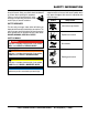
Safety Information Do not operate or service the equipment before reading the entire manual. Safety precautions should be followed at all times when operating this equipment. Failure to read and understand the safety messages and operating instructions could result in injury to yourself and others. Potential hazards associated with the operation of this equipment will be referenced with hazard symbols which may appear throughout this manual in conjunction with safety messages.
Safety Information general saFety caution never operate this equipment without proper protective clothing, shatterproof glasses, respiratory protection, hearing protection, steel-toed boots and other protective devices required by the job or city and state regulations. Avoid wearing jewelry or loose fitting clothes that may snag on the controls or moving parts as this can cause serious injury. never operate this equipment when not feeling well due to fatigue, illness or when under medication.
Safety Information mixer saFety danger never operate the equipment in an explosive atmosphere or near combustible materials. An explosion or fire could result causing severe bodily harm or even death. do not mix flammable or explosive substances. warning never place your hands inside the drum while starting or operating this equipment. never disconnect any emergency or safety devices. These devices are intended for operator safety.
Safety Information Fuel saFety transporting saFety danger caution do not add fuel to equipment if it is placed inside truck bed with plastic liner. Possibility exists of explosion or fire due to static electricity. FUEL never allow any person or animal to stand underneath the equipment while lifting. NOTICE always make sure forklift forks are inserted into pockets (if applicable) as far as possible when lifting the mixer. always shutdown engine before transporting.
specifications Table 1. Mixer Specifications Capacity 12.0 cu. ft (340 liters) Bag Capacity 3 to 4 bags Operating Weight 1580 lbs. (716.68 kg.) Maximum Aggregate Size 1 in. (25.4 mm) Adjustable Drum Discharge Height Up to 42.5 in. (1079.5 mm.) Drive System Hydraulic Dump Action Hydraulic Model Type Bore X Stroke Displacement Max Output Continuous Output Fuel Tank Capacity Fuel Lube Oil Capacity Speed Control Method Starting Method Table 2.
dimensions C A B Figure 1. Mixer Dimensions Table 3. Mixer Dimensions Reference Designator Dimension in. (mm.) A (Length) 73.5 (1917.7) B (Width) 35.0 (889) C (Height) 45.0 (1143) page 10 — Pro12 hydraulic mixer • operation manual — rev.
general Information Application Hardware The Multiquip PRO12 hydraulic mixer (with drum capacity of 12.0 cu. ft./340 liters) is shipped completely assembled, factory-tested, and ready for use. Check all hardware on the mixer before starting. Periodically inspect all hardware. Loose hardware can contribute to early component failure and poor performance. Keep all mixer hardware components tight. This mixer is only intended for the mixing of plaster and mortar.
Mixer components 3 6 1 5 2 8 4 13 12 9 11 14 10 Figure 2. Mixer Components page 12 — Pro12 hydraulic mixer • operation manual — rev.
Mixer components 1. Engine Cover — Lift this cover to gain access to the engine or electric motor. 2. Start/Stop Switch — This switch is located on the side of the engine cover. When activated it will shut down the engine. 3. Latch — Use this latch to secure the engine compartment enclosure. 4. Drum Bearing — There is a sealed bearing on each end of the mixing drum. Bearings are packed and sealed at the factory and require no further maintenance. 5.
hydraulic components 6 5 8 1 3 7 2 4 2 Figure 3. Hydraulic Components page 14 — Pro12 hydraulic mixer • operation manual — rev.
hydraulic components 1. Hydraulic Motor — Bi-directional hydraulic motor that is used in conjunction with the directional control valve to operate the hydraulic dump cylinder and paddle shaft. 2. Hydraulic Dump Cylinder — When activated, this cylinder will cause the mixing drum to rotate to the dump position. This cylinder is provided on mixers with hydraulic dump capability. 3. Hydraulic Oil Sight Gauge — This gauge indicates the level and temperature of the hydraulic oil.
basic engine 2. Throttle Lever — Used to adjust engine RPM speed (lever advanced forward SLOW, lever back toward operator FAST). 1 10 9 3. Engine ON/OFF Switch — ON position permits engine starting, OFF position stops engine operations. 2 3 8 4. Recoil Starter (pull rope) — Manual-starting method. Pull the starter grip until resistance is felt, then pull briskly and smoothly. 5. Fuel Valve Lever — OPEN to let fuel flow, CLOSE to stop the flow of fuel. 7 6.
paddle blade adjustment STEEL DRUM CAST PADDLE CENTER TOW END CAST PADDLE DRUM END ENGINE END CAST PADDLE PADDLE BLADE IS TOO TIGHT AGAINST DRUM SIDE WALLS. INCORRECT ROTATION DRUM SIDE END PADDLE BLADE CENTER ENGINE END CAST PADDLE INCORRECT INCORRECT CORRECT CORRECT SIDE PADDLE BLADE ROTATION PADDLE BLADE IS TOO TIGHT AGAINST DRUM SIDE WALLS. DRUM END AND SIDE WALLS Figure 5. Paddle Blade Adjustment Pro12 hydraulic mixer • operation manual — rev.
inspection Before Starting 1. Read safety instructions at the beginning of manual. 2. Clean the mixer, removing dirt and dust, particularly the engine cooling air inlet, carburetor and air cleaner. 3. Check the air filter for dirt and dust. If air filter is dirty, replace air filter with a new one as required. 4. Check carburetor for external dirt and dust. Clean with dry compressed air. 5. Check fastening nuts and bolts for tightness. Engine Oil Check Season Summer Spring/Fall Winter Table 4.
inspection Hydraulic Hoses Grease Fitting (dump cylinder) Check hydraulic hoses (Figure 3) to make sure they are not worn, frayed or defective. Check the zerk grease fittings on the dump cylinder (Figure 10). This grease fitting lubricates the hydraulic dumping mechanism. Grease Fittings (Bearings) Check the zerk grease fittings (Figure 9) at each end of the mixing drum. These grease fittings lubricate the paddle shaft bearings.
startup CAUTION DO NOT attempt to operate the mixer until the Safety, General Information and Inspection sections of this manual have been read and thoroughly understood. This section is intended to assist the operator with the initial start-up of the mixer. It is extremely important that this section be read carefully before attempting to use the mixer in the field. Starting the Engine (HONDA engine) 1. Place the engine fuel valve lever (Figure 11) to the “ON” position. Figure 13.
startup 7. Turn the engine ignition key (Figure 17) to the START position and hold it until the engine starts. When engine starts, release the key, allowing it to return to the ON position. OFF O N Stopping the Engine Normal Shutdown 1. Move the throttle lever to the IDLE position (Figure 20) and run the engine for three minutes at low speed. START Figure 17. Engine Ignition Key 8.
operation Mixing 1. On the hydraulic valve, push lever inward (Figure 23) for clockwise mixing rotation of blades. NEUTRAL PUSH IN TO MIX PULL OUT TO REVERSE Figure 23. Hydraulic Paddle Lever 2. The paddle shaft inside the drum should be rotating at this time. 3. Add a small amount water to the mixing drum. 4. Lift the mixing bag compound onto the steel safety grate over the bag cutter and let the contents fall into the drum. Add more water if desired and mix compound to desired consistency. Figure 25.
maintenance Perform engine maintenance procedures as scheduled in Table 5. Description (3) Engine Oil Air Cleaner All Nuts and Bolts Spark Plug Cooling Fins Spark Arrester Fuel Tank Fuel Filter Idle Speed Valve Clearance Fuel lines Operation Table 5.
maintenance Perform the engine maintenance indicated below: Daily 1. Thoroughly remove dirt and oil from the engine and control area. Clean or replace the air cleaner elements as necessary. Check and retighten all fasteners as necessary. Weekly 1. Remove the fuel filter cap and clean the inside of the fuel tank. 2. Remove or clean the filter at the bottom of the tank. 3. Remove and clean the spark plug (Figure 26), then adjust the spark gap to 0.028~0.031 inch (0.6~0.7 mm).
maintenance hydraulic oil filter 9. NEVER pour or spray water over the engine (Figure 30). Replace hydraulic oil filter (Figure 29) every 500 hours. Hydraulic tank capacity is 12 gallons (45 liters). Refill with any of the following hydraulic oil types. Shell Tellius 68, Mobil DFE26 or Texaco Rand HDC. Figure 30. No Spraying of Water 10. When cleaning of the entire mixer is done, return mixing drum to an upright position. Mixer Storage Figure 29.
troubleshooting Practically all breakdowns can be prevented by proper handling and maintenance inspections, but in the event of a breakdown, please take remedial action following the diagnosis based on the troubleshooting tables. If the problem cannot be remedied, please leave the unit as is and consult our company's service department. troubleshooting (engine) Symptom Possible Problem Spark plug bridging? Check gap, insulation or replace spark plug.
troubleshooting troubleshooting (engine) - continued Symptom Weak in power, compression is proper and does not misfire. Weak in power, compression is proper but misfires. Engine overheats. Rotational speed fluctuates. Recoil starter malfunctions. (if applicable) Starter malfunctions. Possible Problem Air cleaner dirty? Clean or replace air cleaner. Improper level in carburetor? Check float adjustment, rebuild carburetor. Defective spark plug? Clean or replace spark plug.
troubleshooting Symptom Blades will not rotate. Material leaking from drum ends. Drum difficult to discharge (tilt). troubleshooting (mixer) Possible Problem Worn or defective V-belt? Solution Replace V-belt. Check position of adjustment lever. Adjustment lever mis-aligned? Adjust if necessary. Material load too heavy, exceeding Reduce amount of material being mixer capability? mixed. Object stuck inside mixing drum, Stop engine. Empty out drum jamming paddle rotation? contents. Remove obstruction.
notes Pro12 hydraulic mixer • operation manual — rev.
hydraulic system LOCATOR 4 5 12 1 13 3 8 2 9 6 7 11 10 page 30 — Pro12 hydraulic mixer • operation manual — rev.
hydraulic system diagram HYDRAULIC SYSTEM DIAGRAM HYDRAULIC DUMP 8 FORWARD/REVERSE 9 12 GEAR PUMP RELIEF VALVE 10 1750 PSI ENGINE 5 RETURN FILTER SUCTION STRAINER BYPASS 25 PSI 3 13 2 2 HYD MOTOR 1 TANK 1 CYLINDER 6 RELIEF VALVE 1750 PSI 4 11 TANK 1 CYLINDER 7 Pro12 hydraulic mixer • operation manual — rev.
Operation Manual HERE’S HOW TO GET HELP PLEASE HAVE THE MODEL AND SERIAL NUMBER ON-HAND WHEN CALLING United StateS Multiquip Corporate Office 18910 Wilmington Ave. Carson, CA 90746 Contact: mq@multiquip.com MQ Parts Department Tel.