OPERATION AND PARTS MANUAL SERIES MODEL MVH-120GH REVERSIBLE PLATE COMPACTOR (HONDA GX160K1SM12/GX160U1SM12/ GX160U1SMX4 GASOLINE ENGINE) Revision #3 (10/24/07) To find the latest revision of this publication, visit our website at: www.multiquip.com THIS MANUAL MUST ACCOMPANY THE EQUIPMENT AT ALL TIMES.
PROPOSITION 65 WARNING l PAGE 2 — MVH-120GH — OPERATION AND PARTS MANUAL — REV.
NOTE PAGE MVH-120GH — OPERATION AND PARTS MANUAL — REV.
TABLE OF CONTENTS Proposition 65 Warning ............................................. 2 Table Of Contents ..................................................... 4 Parts Ordering Procedures ....................................... 5 Safety ..................................................................... 6-7 Rules For Safe Operation ...................................... 8-9 Specifications .......................................................... 10 General Information ...................................
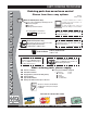
www.multiquip.com PARTS ORDERING PROCEDURES Ordering parts has never been easier! Choose from three easy options: Effective: January 1st, 2006 Best Deal! Order via Internet (Dealers Only): If you have an MQ Account, to obtain a Username and Password, E-mail us at: parts@multiquip.com. Order parts on-line using Multiquip’s SmartEquip website! ■ View Parts Diagrams ■ Order Parts ■ Print Specification Information To obtain an MQ Account, contact your District Sales Manager for more information.
SAFETY FOR YOUR SAFETY AND SAFETY OF OTHERS! HAZARD SYMBOLS Safety precautions should be followed at all times when operating this equipment. Failure to read and understand the Safety Messages and Operating Instructions could result in injury to yourself and others. Potential hazards associated with the operation of this equipment will be referenced with Hazard Symbols which appear throughout this manual, and will be referenced in conjunction with Safety Message Alert Symbols.
SAFETY CAUTION — Rotating Parts Hazards NEVER operate equipment with covers or guards removed. Keep fingers, hands, hair and clothing away from all moving parts to prevent injury. CAUTION — Overspeed Conditions NEVER tamper with the factory setting of the engine governor. Personal injury and equipment damage can result if operating in speed ranges above the maximum allowable.
RULES FOR SAFE OPERATION WARNING — Read This Manual Failure to follow instructions in this manual may lead to serious injury or even DEATH! This equipment is to be operated by trained and qualified personnel only! This equipment is for industrial use only. general safety DO NOT operate or service this equipment before reading this entire manual. This equipment should not be operated by persons under 18 years of age.
RULES FOR SAFE OPERATION LOADING AND UNLOADING Before lifting, make sure that equipment parts (hook and vibration insulator) are not damaged and screws are not loosened or lost. REFUELING FUEL ALWAYS make sure crane or lifting device has been properly secured to the lifting bail (hook) of the equipment. NEVER lift the equipment while the engine is running. Use adequate lifting cable (wire or rope) of sufficient strength. Use one point suspension hook and lift straight upwards.
MVH-120GH — SPECIFICATIONS TABLE 1. COMPACTOR SPECIFICATIONS Model MVH-120GH Centrifugal Force Number of Vibrations 5,200 lbs. (2,350 kg) 6,000 v/min Traveling Speed 75 ft./min (23 meters/min) Plate Size (LxW) 23 x 15.7 x 39 in. (584 x 399 mm) Dimensions (LxWxH) Operating Weight 35.4 x 15.7 x 39 in. (900 x 399 x 990 mm) 247 lbs. (111 kg.) TABLE 2.
MVH-120GH — GENERAL INFORMATION Definition of Plate Compactor Frequency/Speed The Mikasa MVH-120GH is a walk-behind, reversible plate compactor design for the compaction of sand, clay and asphalt. This plate compactor is a powerful compacting tool capable of applying a tremendous force in consecutive high frequency vibrations to a soil surface.
MVH-120GH — COMPONENTS (PLATE COMPACTOR) 10 FORWARD NEU TR AL REVERSE 1 2 11 6 7 5 3 8 4 9 Figure 1. Compactor Controls Figures 1 and 2 show the location of the controls, indicators and general maintenance parts. The function of each control is described below: 7. Gasoline Engine – This plate compactor uses a HONDA GX160 engine. Refer to the HONDA owner's manual for engine information. 1. Breather Cap – Remove this cap to bleed (remove air) the hydraulic system.
MVH-120GH — COMPONENTS (HONDA GX160 ENGINE) Figure 2. Engine Controls & Components 1. Fuel Filler Cap – Remove this cap to add unleaded gasoline to the fuel tank. Make sure cap is tighten securely. DO NOT over fill. 7. Air Cleaner – Prevents dirt and other debris from entering the fuel system. Remove wing-nut on top of air filter cannister to gain access to filter element. 2. Throttle Lever – Used to adjust engine speed (fast-slow). 8. 3. Recoil Starter (pull rope) – Type of engine starting method.
MVH-120GH — INSPECTION Before Starting The Oil Alert system will automatically stop the engine before the engine falls below safe limits. Always be sure to check the engine oil level prior to starting the engine. 1. Read safety instructions at the beginning of manual. 2. Clean the compactor, removing dirt and dust. Particularly, the bottom of the plate, engine cooling air inlet, carburetor and air cleaner. 3. Check the air filter for dirt and dust.
MVH-120GH — INSPECTION Vibrator Oil Check 1. With handle bar positioned vertically (storage position), remove the breather cap (Figure 6) from the breather plug. 1. To check the V-belt tension (Figure 8 ), remove upper belt cover. 2. Use a 24 mm wrench and remove breather plug (Figure 6). Visually check to see if hydraulic oil comes up to the oil level line that is etched on the back side of the handle. CAP BREATHER PLUG OIL LEVEL Figure 8. V-Belt Location HAND PUMP Figure 6. Vibrator Oil Gauge 2.
MVH-120GH — INITIAL START-UP CAUTION DO NOT attempt to run the compactor until the Safety andD Initial Start-up sections have been read, The CLOSED position of the choke lever enriches the fuel mixture for starting a COLD engine. The OPEN position provides the correct fuel mixture for normal operation after starting, and for restarting a warm engine. 1. Place the fuel valve lever (Figure 10) in the "ON" position. 4. Place the throttle lever (Figure 13) halfway between fast and slow. Figure 10.
MVH-120GH — INITIAL START-UP 5. Grasp the starter grip (Figure 14) and slowly pull it out. The resistance becomes the hardest at a certain position, corresponding the compression point. Rewind the rope a little from that point and pull out sharply. CAUTION z DO NOT pull the starter rope all the way to the end. z DO NOT release the starter rope after pulling. Allow it to rewind as soon as possible. 6. If the engine has started, slowly return the choke lever (Figure 12) to the CLOSED position.
MVH-120GH — OPERATION Operation CAUTION CAUTION Make sure to follow all safety rules referenced in the safety section of this manual before operating compactor. Keep work area clear of debris and other objects that could cause damage to the compactor or bodily injury. 1. Grasp the compactor's hand grip (Figure 15), and move the engine throttle lever quickly from the turtle position (idle) to the rabbit position (full throttle) position.
MVH-120GH — MAINTENANCE CAUTION CAUTION These inspection intervals are for operation under normal conditions. Adjust your inspection intervals based on the number of hours plate compactor is in use, and particular working conditions. Inspection and other services should always be carried out on solid and level ground with the engine shut down. Inspection and Maintenance Service Tables. CAUTION 1.
MVH-120GH — MAINTENANCE Engine Oil Replacement: 1. Replace engine oil, first in 20 hours of operation and every 100 hours afterwards. 2. Oil may be drained more easily when it is warm after operation (For more details, see separate HONDA Owner's Manual). Air Filter 1. The air filter element should be cleaned because a clogged air cleaner can cause poor engine starting, lack of power and shorten engine life substantially. z Replacing the V-belt Remove the upper and lower belt covers.
MVH-120GH — MAINTENANCE 2. After draining, reconnect the hydraulic hose to vibrator. CAUTION Make sure hydraulic oil in hand pump is at a normal save operating level. DO NOT over fill. Over filling (excessive oil) will cause excess oil to blow out of breather plug. Hydraulic Oil Check hydraulic oil in every 100 hours of operation. With handle bar positioned vertically (storage position), remove breather plug (Figure 1) off the top of hydraulic pump and check for proper oil level.
MVH-120GH — PREPARATION FOR LONG -TERM STORAGE Pump Storage For storage of the pump for over 30 days, the following is required: z Drain the fuel tank completely. z Run the engine until the fuel in the injection system is completely consumed. z Completely drain the oil from the engine crankcase and follow procedures described in the HONDA engine Owner's Manual for engine storage. z Completely drain the compactor's hydraulic oil from the vibrating case.
MVH-120GH — TROUBLESHOOTING (ENGINE) TABLE 7. ENGINE TROUBLESHOOTING SYMPTOM Difficult to star t, "fuel is available, but no spark at spark plug". POSSIBLE CAUSE Spark plug bridging? Check gap, insulation or replace spark plug. Carbon deposit on spark plug? Clean or replace spark plug. Shor t circuit due to deficient spark plug insulation? Check spark plug insulation, replace if worn. Improper spark plug gap? Set to proper gap. ON/OFF switch is shor ted? Check switch wiring, replace switch.
MVH-120GH — TROUBLESHOOTING (ENGINE) TABLE 7. ENGINE TROUBLESHOOTING (CONTINUED) SYMPTOM "Weak in power". Compression is proper and does not misfire. "Weak in power". Compression is proper but misfires. Engine overheats. Rotational speed fluctuates. Recoil star ter malfunction. POSSIBLE CAUSE SOLUTION Air cleaner not clean? Clean or replace air cleaner Improper level in carburetor? Check float adjustment, re-build carbureator. Defective Spark plug? Clean or replace spark plug.
MVH-120GH — TROUBLESHOOTING (PLATE COMPACTOR) TABLE 8. PLATE COMPACTOR TROUBLESHOOTING SYMPTOM POSSIBLE CAUSE Engine speed too low? Set engine speed to correct RPM. Clutch slips? Check or replace clutch. Travel speed too low, and vibration is V-belt slips? weak. Excessive oil in vibrator? Tr a v e l s f o r w a r d o r r e v e r s e , b u t impossible to switch direction. D o e s n o t t r a ve l e i t h e r fo r w a r d o r reverse. Tr a v e l l ev e r o p e r a t i n g r e s i s t a n c e great.
MVH-120GH — EXPLANATION OF CODE IN REMARKS COLUMN The following section explains the different symbols and remarks used in the Parts section of this manual. Use the help numbers found on the back page of the manual if there are any questions. The contents and part numbers listed in the parts section are subject to change without notice. Multiquip does not guarantee the availibility of the parts listed. * * Numbers Used - Item quantity can be indicated by a number, a blank entry, or A/R.
MVH-120GH — SUGGESTED SPARE PARTS MVH-120GH PLATE COMPACTOR 1 TO 3 UNITS WITH HONDA GX160 ENGINE Qty. P/N Description 3 070100322 V-BELT Remarks 1 2 2 1 1 5 1 1 1 2 1 458337770 956100035 956100041 956200050 362910060 9807955846 36100ZH7003 36100ZF6P81 36100ZF6P82 17218ZE1505 17620Z0T305 1 1 17620Z4H000 17672ZE2W01 1 1 1 17672Z4H000 30500ZE1043 28462ZH8003 CLUTCH ASSY. THROTTLE WIRE ................................ MVH-120GH S/N L3080 AND BELOW THROTTLE WIRE ................................
MVH-120GH — NAME PLATE AND DECALS NAME PLATE AND DECALS 9 1 3 SHELL TELLUS OIL 46 NPA-748 J 2 NPA-333 OPERATIONAL CAUTION Prior to OPERATION: Check engine oil and fuel level if not enough, add to proper level To START engine: 1. Warm up engine at low speed for 3 to 5 minutes. 8 2. Operate machine always at full speed to avoid incorrect clutch engagement. 3. Use travel lever for forward and reverse motion. Do not push or pull lever strongly. To STOP engine: Move stop switch to “OFF” position.
MVH-120GH — NAME PLATE AND DECALS NAME PLATE AND DECALS NO PART NO PART NAME 1 2 3 4 5 6 7 8 9 920207480 950207430 920203330 920201580 920207420 DECAL, SHELL TELLUS OIL 46 1 DECAL, CAUTION (MVH-120) 1 EAR PROTECTION LABEL 1 DECAL, MQ MARK 71X55 1 DECAL, V- BELT RPF-3320 1 PLATE, SERIAL NO. ......................... 1 ............ CONTACT MQ PARTS DEPARTMENT DECAL, MOTOR OIL /NPA-195 1 DECAL, MODEL/MVH-120 1 DECAL, DANGER-CAUTION 1 KIT, DECAL ....................................... 1 ............
MVH-120GH — VIBRATING PLATE ASSY. VIBRATING PLATE ASSY. 5 2 6 7 2 7 6 5 9 10 11 4 1 3 4 l l 11 (FOR BELT ADJUSTMENT) PAGE 30 — MVH-120GH — OPERATION AND PARTS MANUAL — REV.
MVH-120GH — VIBRATING PLATE ASSY. VIBRATING PLATE ASSY. NO PART NO PART NAME 1 2 3 4 5 6 7 9 10 11 458115140 458450620 0039312000 030212300 022131210 030212300 952400710 460449160 953405260 952401190 VIBRATING PLATE 1 SHOCK ABSORBER 4 NUT M12 ..................................................... 4 ............ REPLACES 020312100 WASHER, LOCK M12 4 CAP NUT M12 4 SW M12 4 WASHER 13304 4 OIL CHANGE 1 PACKING ¼ 1 WASHER 13X43X4.5 .................................. 4 ............ NEW VERSION ONLY QTY.
MVH-120GH — BODY ASSY. (OLD VERSION) BODY ASSY. SERIAL NUMBER L3029 AND BELOW) l PAGE 32 — MVH-120GH — OPERATION AND PARTS MANUAL — REV.
MVH-120GH — BODY ASSY. (OLD VERSION) BODY ASSY.
MVH-120GH — BODY ASSY. (NEW VERSION) BODY ASSY. BODY ASSY. SERIAL NUMBER L3030 AND ABOVE) 36 37 39 35 52 53 51 47 48 38 40 41 45 43 42 44 46 43 41 44 12-1 6 12-2 12-3 12-4 12 12-6 12-7 11 13 14 12-8 15 2 3 4 5 8 l 20 7 l 16 19 1 18 17 PAGE 34 — MVH-120GH — OPERATION AND PARTS MANUAL — REV.
MVH-120GH — BODY ASSY. (NEW VERSION) BODY ASSY. BODY ASSY.
MVH-120GH — VIBRATOR ASSY. (OLD VERSION) VIBRATOR ASSY. (SERIAL NUMBER L3112 AND BELOW) l PAGE 36 — MVH-120GH — OPERATION AND PARTS MANUAL — REV.
MVH-120GH — VIBRATOR ASSY. (OLD VERSION) VIBRATOR ASSY.
MVH-120GH — VIBRATOR ASSY. (NEW VERSION) VIBRATOR ASSY. (SERIAL NUMBER L3113 AND ABOVE) A 22 23 24 21 2 30 5 5 6 3 2 18 19 41 9-B 31-B 42 43 9-B 19 36 18 12 4-B 5 18 2 35 19 32 33 37 39 38 18 19 34 20 40 42 43 16 27 28 29 l l 15 14 13 1 17 25 11 26 47 48 2 5 45 46 PAGE 38 — MVH-120GH — OPERATION AND PARTS MANUAL — REV.
MVH-120GH — VIBRATOR ASSY. (NEW VERSION) VIBRATOR ASSY.
MVH-120GH — CONTROL ASSY. (OLD VERSION) CONTROL ASSY. (SERIAL NO. L3080 AND BELOW) l PAGE 40 — MVH-120GH — OPERATION AND PARTS MANUAL — REV.
MVH-120GH — CONTROL ASSY. (OLD VERSION) CONTROL ASSY. (SERIAL NO.
MVH-120GH — CONTROL ASSY. (NEW VERSION) CONTROL ASSY. (SERIAL NO. L3081 AND ABOVE) A 64 63 60 13 62 27 28 65 66 56 68 69 12 61 60 26 40 59 60 55 15 11 58 53 70 52 54 57 15 19 14 13 17 81 18 31-1 16 51 1 35 36 9 10 32 34 2 l l 3 23 24 35 7 30 22 4 36 3 21 4 20 71 8 7 29 PAGE 42 — MVH-120GH — OPERATION AND PARTS MANUAL — REV.
MVH-120GH — CONTROL ASSY. (NEW VERSION) CONTROL ASSY. (SERIAL NO.
HONDA GX160 ENGINE — CYLINDER HEAD ASSY. CYLINDER HEAD ASSY. l PAGE 44 — MVH-120GH — OPERATION AND PARTS MANUAL — REV.
HONDA GX160 ENGINE — CYLINDER HEAD ASSY. CYLINDER HEAD ASSY. NO 1 2# 4# 6#% 7 8 9 10 11 12 13 14 16 ,+ 16,+ ,+ 16,+ 17 17 PART NO 12210ZH8405 12204ZE1306 12205ZE1315 12216ZE5300 12251ZF1800 12310ZE1020 12391ZE1000 15721ZH8000 90013883000 90043ZE1020 90047ZE1000 9430110160 957230806000 957230806000 957010806000 9807955846 9807955855 NOTE PART NAME QTY. REMARKS HEAD COMP., CYLINDER ...................... 1 ......... INCLUDES ITEMS W/# GUIDE, IN. VALVE (O.S.), OPTION 1 GUIDE, EX. VALVE (O.S.), OPTION ...
HONDA GX160 ENGINE — CYLINDER BARREL ASSY. CYLINDER BARREL ASSY. l PAGE 46 — MVH-120GH — OPERATION AND PARTS MANUAL — REV.
HONDA GX160 ENGINE — CYLINDER BARREL ASSY. CYLINDER BARREL ASSY. NO 1 2 ,+ 2, ,+ 2, 3 4% 5% 6% 7 8 12 13 14 15 16# 17# 18 19 20 21 23 PART NO 12000ZH8426 15510ZE1033 15510ZE1033 15510ZE1033 16510ZE1000 16511ZE1000 16512ZE1000 16513ZE1000 16531ZE1000 16541ZE1000 90131ZE1000 90451ZE1000 90601ZE1000 90602ZE1000 91001ZF1003 91201Z0T801 91353671004 9405010000 9410106800 9425108000 957010601200 NOTE PART NAME QTY. REMARKS BARREL ASSY., CYL. (OIL ALERT) ....... 1 ......... INCLUDES ITEMS W/# SWITCH ASSY.
HONDA GX160 ENGINE — CRANKCASE COVER ASSY. CRANKCASE COVER ASSY. l PAGE 48 — MVH-120GH — OPERATION AND PARTS MANUAL — REV.
HONDA GX160 ENGINE — CRANKCASE COVER ASSY. CRANKCASE COVER ASSY. NO 1 4 5 6 8#+ 13% 14 16 17% PART NO 11300ZZE1634 11381ZH8801 15600ZE1003 15600ZG4003 15625ZE1003 91201Z0T801 9430108140 957010803200 961006205010 PART NAME QTY. REMARKS COVER ASSY. CRANKCASE ................. 1 ......... INCLUDES ITEMS W/% GASKET CRANKCASE 1 OIL GAUGE/CAP ASSY. (GRAY) ........... 1 ......... INCLUDES ITEMS W/# OIL PLUG ASSY. .................................... 1 .........
HONDA GX160 ENGINE — CRANKSHAFT ASSY. CRANKSHAFT ASSY. l PAGE 50 — MVH-120GH — OPERATION AND PARTS MANUAL — REV.
HONDA GX160 ENGINE — CRANKSHAFT ASSY. CRANKSHAFT ASSY. NO 1+ + + 2+ 3 4 PART NO 92101080250A 90473842000 90741883810 13310ZE1000 NOTE PART NAME BOLT WASHER 8 MM KEY 5X5X33 (YELLOW) CRANKSHAFT COMP. QTY. 1 1 1 1 REMARKS GX160K1SM12: MODEL MVH120G S/N F-1104 (1998-2004) , GX160U1SM12: MODEL MVH120G S/N F-1105 (2005) + GX160U1SMX4: MODEL MVH120G S/N P-4378 AND ABOVE (2006) MVH-120GH — OPERATION AND PARTS MANUAL — REV.
HONDA GX160 ENGINE — PISTON ASSY. PISTON ASSY. l PAGE 52 — MVH-120GH — OPERATION AND PARTS MANUAL — REV.
HONDA GX160 ENGINE — PISTON ASSY. PISTON ASSY.
HONDA GX160 ENGINE — CAMSHAFT ASSY. CAMSHAFT ASSY. l PAGE 54 — MVH-120GH — OPERATION AND PARTS MANUAL — REV.
HONDA GX160 ENGINE — CAMSHAFT ASSY. CAMSHAFT ASSY. NO 1 3 5 6 7 8# 9 10 11 12 13 14 15 16 17 18 ,+ 18,+ PART NO 14100ZE1812 14410ZE1010 14431ZE1000 14441ZE1010 14451ZE1013 14568ZE1000 14711ZF1000 14721ZF1000 14751ZF1000 14771ZE1000 14773ZE1000 14781ZE1000 14791ZE1010 90012ZE0010 90206ZE1000 14781ZE1000 12209ZH8003 NOTE PART NAME QTY. REMARKS CAMSHAFT ASSY. ................................. 1 .........
HONDA GX160 ENGINE — RECOIL STARTER ASSY. RECOIL STARTER ASSY. l PAGE 56 — MVH-120GH — OPERATION AND PARTS MANUAL — REV.
HONDA GX160 ENGINE — RECOIL STARTER ASSY. RECOIL STARTER ASSY.
HONDA GX160 ENGINE — FAN COVER ASSY. FAN COVER ASSY. l PAGE 58 — MVH-120GH — OPERATION AND PARTS MANUAL — REV.
HONDA GX160 ENGINE — FAN COVER ASSY. FAN COVER ASSY. NO 1 ,+ 1, ,+ 1, 2 3 ,+ 3, ,+ 3, 4 5 6 7 8 ,+ 8, ,+ 8, 9 PART NO 19610ZE1000ZC 19610ZE1000ZC 19610ZE1010ZC 19630ZH8000 36100ZH7003 36100ZF6P81 36100ZF6P82 90013883000 90022888010 90601ZH7013 19611ZH8810 34150ZH7003 34150ZH7003 34150ZH7013 957010600800 NOTE PART NAME QTY. REMARKS COVER COMP., FAN NH1 1 COVER COMP., FAN NH1 ............... 1 ...... S/N 1120542 AND BELOW COVER COMP., FAN NH1 ............... 1 ......
HONDA GX160 ENGINE — CARBURETOR ASSY. CARBURETOR ASSY. l PAGE 60 — MVH-120GH — OPERATION AND PARTS MANUAL — REV.
HONDA GX160 ENGINE — CARBURETOR ASSY. CARBURETOR ASSY.
HONDA GX160 ENGINE — AIR CLEANER ASSY. AIR CLEANER ASSY. l PAGE 62 — MVH-120GH — OPERATION AND PARTS MANUAL — REV.
HONDA GX160 ENGINE — AIR CLEANER ASSY. AIR CLEANER ASSY. NO 1 2 PART NO 16271ZE1000 17210ZE1505 3# 4 5# , 6 7% 8% 9 10 11 12 17218ZE1505 17230ZE1820 17232891000 17235ZE1831 17238ZE7010 17239ZE1000 17410ZE1020 90325044000 9405006000 957010602000 NOTE PART NAME QTY. REMARKS PACKING, ELBOW 1 CLEANER ELEMENT .................. 1 .......... INCLUDES ITEMS W/# ................................................................. REPLACES 17210ZE1822 OUTER ELEMENT ...................... 1 ..........
HONDA GX160 ENGINE — MUFFLER ASSY. MUFFLER ASSY. l PAGE 64 — MVH-120GH — OPERATION AND PARTS MANUAL — REV.
HONDA GX160 ENGINE — MUFFLER ASSY. MUFFLER ASSY. NO 1 2 3 4 5 6 7 8 9 10 + 11+ PART NO 18310ZH8810 19320ZF1H01 18340ZE1010 18355ZE1000 18381ZH8800 18522ZE1000 90002ZG0003 90050ZE1000 90055ZE1000 020108060 90016ZE1000 NOTE PART NAME QTY. REMARKS MUFFLER COMP. 1 PROTECTOR, MUFFLER 1 DEFLECTOR COMP. 1 ARRESTOR, SPARK 1 GASKET, MUFFLER 1 GUIDE, MUFFLER 1 SCREW, TAPPING 4X8 2 SCREW, TAPPING 5X8 5 SCREW, TAPPING 4X6 1 NUT, HEX 8MM ....................................... 2 .........
HONDA GX160 ENGINE — FUEL TANK ASSY. FUEL TANK ASSY. l PAGE 66 — MVH-120GH — OPERATION AND PARTS MANUAL — REV.
HONDA GX160 ENGINE — FUEL TANK ASSY. FUEL TANK ASSY. NO 1 ,+ 1, PART NO 17620Z0T305 17620Z0T305 ,+ 1, 17620Z4H000 2# ,+ 2,+ ,++ ,+ % 2,+ 3 ,+ 3, ,+ 3, 4 + , 4, , 4, 5 6 7 8 9 , 9, + ,+ 9, 10 ,+ 10,+ ,+ 10,+ 11 17631Z0T812 17631Z0T812 17631Z0T801 17672ZE2W01 17672ZE2W01 117672Z4H000 17510ZE1020ZF 17510ZE1020ZF 17510ZE1030ZF 9405006000 90004ZH7003 91353671003 16955ZE1000 9500202080 9500202080 950024080008 950014514040 90014514040 91424Z4F801 16854ZH8000 NOTE PART NAME QTY.
HONDA GX160 ENGINE — FLYWHEEL ASSY. FLYWHEEL ASSY. l PAGE 68 — MVH-120GH — OPERATION AND PARTS MANUAL — REV.
HONDA GX160 ENGINE — FLYWHEEL ASSY. FLYWHEEL ASSY. NO 1 2 3 4 4 ,+ 4, 5 PART NO 31100ZE1010 13331357000 19511ZE1000 28451ZH8003 28451ZH8801 28451ZH8801 90201878003 NOTE PART NAME QTY. REMARKS FLYWHEEL COMP. 1 WOODRUFF KEY 25X18 1 FAN, COOLING 1 PULLEY, STARTER ................................ 1 ......... S/N 8805657 AND BELOW PULLEY, STARTER ................................ 1 .........
HONDA GX160 ENGINE — IGNITION COIL ASSY. IGNITION COIL ASSY. l PAGE 70 — MVH-120GH — OPERATION AND PARTS MANUAL — REV.
HONDA GX160 ENGINE — IGNITION COIL ASSY. IGNITION COIL ASSY. NO 1 2 3 3 ,+ 3, ,+ 3, 4 PART NO 36101ZE1010 30600ZE1013 30500ZE1043 30500ZE1053 30500ZE1063 30500ZE1073 90121952000 NOTE PART NAME QTY. REMARKS CORD, STOP SWITCH (370 MM) 1 CAP ASSY., NOISE SUPPRESSOR 1 COIL ASSY., IGNITION .......................... 1 ......... S/N 8954625 AND BELOW COIL ASSY., IGNITION .......................... 1 ......... S/N 8954626 AND ABOVE COIL ASSY., IGNITION .......................... 1 .........
HONDA GX160 ENGINE — CONTROL ASSY. CONTROL ASSY. l PAGE 72 — MVH-120GH — OPERATION AND PARTS MANUAL — REV.
HONDA GX160 ENGINE — CONTROL ASSY. CONTROL ASSY. NO 1 2 3 4 5 6 7 8 9# 10# 11# 12# 13# 14# 15# 16# 17# 18# 19# 20# 21# 22# + 23+ + 24+ PART NO 16500ZH8U43 90013883000 16561ZE1020 90015ZE5010 16551ZE0010 9405006000 16562ZE1020 16555ZE1000 93500040060H 16594883010 90605230000 90114SA0000 16575ZH8000 16574ZE1000 16571ZH8020 16578ZE1000 16580ZH8813 16584883300 93500050250H 16592ZE1810 93500050160A 16576891000 16599ZG1M10 90016ZG9N30 NOTE PART NAME QTY. REMARKS CONTROL ASSY. ..................................
HONDA GX160 ENGINE — LABEL ASSY. LABEL ASSY. l PAGE 74 — MVH-120GH — OPERATION AND PARTS MANUAL — REV.
HONDA GX160 ENGINE — LABEL ASSY. LABEL ASSY. NO 1 ,+ 1, 2 3 ,+ 4, ,+ 5, 6 ,+ 6, ,+ 6, PART NO 87528ZE1810 87528ZH7000 87522ZH9010 87532ZH8810 87516ZH7810 87532ZH7000 87521ZH8030 87521ZH8030 87521ZH8040 NOTE PART NAME QTY. REMARKS MARK, CHOKE 1 MARK, CHOKE (GRAY) 1 LABEL, CAUTION (ENGLISH ETC.) 1 MARK, OIL ALERT (EXTERNAL) 1 MARK, OPERATOR CAUTION (ENGLISH) 1 MARK, THROTTLE INDICATION 1 EMBLEM (GX160 5.5) 1 EMBLEM (GX160 5.5) ................................. 1 ................
HONDA GX160 ENGINE — TOOLS ASSY. TOOLS ASSY. l PAGE 76 — MVH-120GH — OPERATION AND PARTS MANUAL — REV.
HONDA GX160 ENGINE — TOOLS ASSY. TOOLS ASSY. NO 1 2 PART NO 89218ZE1000 89219805000 PART NAME WRENCH COMPLETE, SPARK PLUG HANDLE, BOX WRENCH QTY. 1 1 REMARKS MVH-120GH — OPERATION AND PARTS MANUAL — REV.
Effective: February 22, 2006 TERMS AND CONDITIONS OF SALE — PARTS PAYMENT TERMS 5. Parts must be in new and resalable condition, in the original Multiquip package (if any), and with Multiquip part numbers clearly marked. 6. The following items are not returnable: Terms of payment for parts are net 30 days. FREIGHT POLICY All parts orders will be shipped collect or prepaid with the charges added to the invoice. All shipments are F.O.B. point of origin.
NOTE PAGE MVH-120GH — OPERATION AND PARTS MANUAL — REV.
OPERATION AND PARTS MANUAL HERE’S HOW TO GET HELP PLEASE HAVE THE MODEL AND SERIAL NUMBER ON-HAND WHEN CALLING UNITED STATES Multiquip Corporate Office 18910 Wilmington Ave. Tel. (800) 421-1244 Carson, CA 90746 Fax (800) 537-3927 Contact: mq@multiquip.com Mayco Parts 800-306-2926 Fax: 800-672-7877 310-537-3700 Fax: 310-637-3284 Service Department 800-421-1244 Fax: 310-537-4259 310-537-3700 MQ Parts Department 800-427-1244 310-537-3700 MEXICO UNITED KINGDOM MQ Cipsa Carr. Fed. Mexico-Puebla KM 126.