OPERATION MANUAL DRY PRIME PUMP MP150SDLTE (6-inch, High Flow, Deutz F3L914, Electric Brakes) MP150SDLTS (6-inch, High Flow, Deutz F3L914, Surge Brakes) MP150SDLSM (6-inch, High Flow, Deutz F3L914, Skid Mount) MP200DLTE (8-inch, High Flow, Deutz F3L914, Electric Brakes) MP200DLTS (8-inch, High Flow, Deutz F3L914, Surge Brakes) MP200DLSM (8-inch, High Flow, Deutz F3L914, Skid Mount) MP200SDLTE (8-inch, High Flow, Deutz F4L914, Electric Brakes) MP200DLST (8-inch, High Flow, Deutz F4L914, Surge Brakes) MP200S
PROPOSITION 65 WARNING Diesel engine exhaust and some of PAGE 2 —DRY PRIME PUMP — OPERATION MANUAL — REV.
REPORTING SAFETY DEFECTS REPORTING SAFETY DEFECTS If you believe that your vehicle has a defect that could cause a crash or could cause injury or death, you should immediately inform the National Highway Traffic Safety Administration (NHTSA) in addition to notifying Multiquip at 1-800-421-1244. If NHTSA receives similar complaints, it may open an investigation, and if it finds that a safety defect exists in a group of vehicles, it may order a recall and remedy campaign.
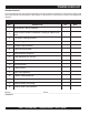
TRAINING CHECKLIST TRAINING CHECKLIST This checklist will lists some of the minimum requirements for machine maintenance and operation. Please feel free to detach it and make copies. Use this checklist whenever a new operator is to be trained or it can be used as a review for more experienced operator’s. TRAINING CHECKLIST NO. DESCRIPTION 1 Read Operator’s Manual completely. 2 Machine layout, location of components, checking of engine and oil levels. 3 Fuel system, refueling procedure.
DAILY PRE-OPERATION CHECKLIST DAILY PRE-OPERATION CHECKLIST DAILY PRE-OPERATION CHECKLIST 1 Check engine oil level. 2 Check fuel level (and for clean fuel). 3 Check cooling fins and cooling air flow. 4 Check engine air cleaner. 5 Check engine battery and cable connections. 6 Check pump interior (impeller and volute). 7 Check vacuum pump seal oil. 8 Check bearing housing oil. 9 Check pump seal. 10 Check pump casing for cracks. 11 Check trailer wheel lug nuts for tightness.
TABLE OF CONTENTS Multiquip Dry Prime Diesel Powered Trash Pump California Proposition 65 Warning ............................. 2 Reporting Safety Defects .......................................... 3 Training Checklist ...................................................... 4 Daily Pre-Operation Checklist ................................... 5 Table Of Contents ..................................................... 6 Safety Message Alert Symbols .............................. 8-9 Rules For Safe Operation .....
NOTES DRY PRIME PUMP — OPERATION AND PARTS MANUAL — REV.
SAFETY MESSAGE ALERT SYMBOLS FOR YOUR SAFETY AND THE SAFETY OF OTHERS! Safety precautions should be followed at all times when operating this equipment. Failure to read and understand the Safety Messages and Operating Instructions could result in injury to yourself and others. NOTE This Owner's Manual has been developed to provide complete instructions for the safe and efficient operation of the Multiquip Model Dry Prime Pump.
SAFETY MESSAGE ALERT SYMBOLS Accidental Starting Respiratory Hazard ALWAYS place the engine ON/OFF switch in the OFF position. Close the vandal cover door on the engine control box. Lock the door by placing a pad lock on the door hasp when the machine is not in use. ALWAYS wear approved respiratory protection. Equipment Damage Messages Sight and Hearing Hazard ALWAYS wear approved eye and hearing protection.
RULES FOR SAFE OPERATION DANGER Read this manual! Failure to follow instructions in this manual may lead to serious injury or even death! This equipment is to be operated by trained and qualified personnel only! This equipment is for industrial use only. The following safety guidelines should always be used when operating the Dry Prime Pump: GENERAL SAFETY ■ DO NOT operate or service this equipment before reading this entire manual. ■ This equipment should not be operated by persons under 18 years of age.
RULES FOR SAFE OPERATION ■ NEVER pump volatile, flammable or low flash point fluids. These fluids could ignite or explode. ■ NEVER pump corrosive chemicals or water containing toxic substances. These fluids could create serious health and environmental hazards. Contact local authorities for assistance. ■ NEVER open the volute cover during operation or start the pump with the cover off. The rotating impeller inside the pump can cut or sever objects caught in it.
RULES FOR SAFE OPERATION Battery The battery contains acids that can cause injury to the eyes and skin. To avoid eye irritation, always wear safety glasses or face shielding. Use well-insulated gloves when picking up the battery. Use the following guidelines when handling the battery. ■ DO NOT drop the battery. Any impact to the battery may cause it to explode. ■ DO NOT expose the battery to open flames, sparks, lit cigarettes etc. The battery contains combustible gases and liquids.
PUMP DIMENSIONS A C B Figure 1. Pump Dimensions TABLE 3. PUMP DIMENSIONS REFERENCE LETTER DESCRIPTION DIMENSIONS INCHES (MM) A HEIGHT 47 INCHES (1193.8 MM) B WIDTH 48.5 INCHES ( 1231.97 MM) C DEPTH 45.6 INCHES (1158.14 MM) DRY PRIME PUMP — OPERATION AND PARTS MANUAL — REV.
TRAILER DIMENSIONS Figure 2. Trailer Dimensions TABLE 2. TRAILER DIMENSIONS REFERENCE LETTER DESCRIPTION DIMENSIONS INCHES (MM) A HEIGHT 85.53 INCHES (2172.34 MM) B WIDTH 72.73 INCHES (1847.34 MM) C LENGTH (Tongue Extended) 141.56 INCHES (3595.66 MM) D SHIPPING LENGTH 94 INCHES (2387.6 MM) E SUCTION HEIGHT TBD F DISCHARGE HEIGHT TB D G HITCH HEIGHT AND RANGE TBD PAGE 14 —DRY PRIME PUMP — OPERATION MANUAL — REV.
SPECIFICATIONS TABLE 1. PUMP SPECIFICATIONS Model MP150SDLSM MP150SDLTE MP150SDLTS MP200DLSM MP200DLTE MP200DLTS MP200SDLSM MP200SDLTE MP200SDLTS Maximum Pumping Capacity 2500 GPM (9.4 m3/min.) 2500 GPM (9.4 m3/min.) 2500 GPM (9.4 m3/min.) 2700 GPM (10.2 m3/min.) 2700 GPM (10.2 m3/min.) 2700 GPM (10.2 m3/min.) 3500 GPM (13.2 m3/min.) 3500 GPM (13.2 m3/min.) 3 5 0 0 GP M (13.2 m3/min.) Maximum Suction Lift 30 ft. (9.1 meters) 30 ft. (9.1 meters) 30 ft. (9.1 meters) 25 ft. (7.
SPECIFICATIONS (ENGINE) TABLE 4. ENGINE SPECIFICATIONS Engine Make Deutz De u t z Engine Model F3L914 F4L914 Engine Type Air Cooled Air Cooled 3 4 Bore/Stroke 4/5.2 in 102/132 mm 4/5.2 in 102/132 mm Displacement 197.5 cu-in (3236 cc) 263.3 cu-in (4314 cc) Engine HP 40 HP (29.8 kW) 52 HP (38.8 kW) Oil Capacity 2.53 gal (9.6 liters) 3.43 gal (13.0 liters) Diesel Diesel 140 gal (532 liters) 140 gal (532 liters) 652.57 lbs. (296 kg) 800.28 lbs.
GENERAL INFORMATION The Multiquip Dry Prime pump is a prime dry and primeassist pump that can handle dewatering, sewer bypass, and wellpoint applications. The Dry Prime pump uses a vacuum pump to remove the air. This becomes important in certain applications such as long suction hose runs or multiple suction points (such as wellpoints). In these cases, high volumes of air enters into the pump.
PUMP COMPONENTS 13 6 10 15 12 4 5 14 9 13 1 8 4 2 7 3 1 11 Figure 3-A. Pump Components 14 Figure 3-A shows the location of the components of the Dry Prime pump. The function of each component or control is described below: 1. Rear Fuel Tank Drain Plugs – Remove either plug to drain fuel. 2. Primary Tank Drain Valve – Open valve to drain water from priming tank. In freezing weather conditions water inside priming pump should always be drained. 3.
PUMP COMPONENTS 23 24 26 27 28 21 22 20 17 19 25 18 33 29 16 30 32 31 Figure 3-B. Pump Components Figure 3-B shows the location of the more components of the Dry Prime pump, The function of each component or control is described below: 16. Safety Chain – ALWAYS attach safety chain to the towing vehicle. NEVER tow the pump with the safety chain unattached! See towing section of this manual. 17. Towing Coupler/Ring – Attach this coupler to the towing vehicle.
ENGINE COMPONENTS 4 7 3 6 5 9 13 2 12 1 11 10 8 Figure 4. Basic Engine Components Figure 4 illustrates the location of the basic components for the Deutz Model F3L914 and F4L914 Engines. The function of each component is described below: 1. 2. 3. 7. Starter Motor/Solenoid – NEVER allow concrete or any foreign debris to come in contact with the starter motor/ solenoid. Air Cleaner – Prevents dirt and other debris from entering the fuel system.
ENGINE CONTROL BOX COMPONENTS 8 10 12 14 16 20 VD O 10 RPM 30 0 x100 40 VDO PSI 40 20 60 0 1 2 3 4 0 bar 80 5 QUAR TZ 0 0 02 5 5 HOURS VDO F 200 260 120 300 120 90 50 C 150 VDO AUTO STAR T OFF (WHEN EQUIP PED) P 0 RUN I AUX II 1 III AUX START 2 8 8 10 1 12 VD 14 16 2 20 10 O RPM 30 0 x100 40 VDO PSI 40 20 60 0 1 2 3 4 0 bar 7 80 5 QUAR TZ 0 0 02 5 5 HOURS F 200 VDO 260 120 300 120 90 50 C 150 3 VDO 4 AUTO STA OFF RT (WHEN EQU IPP
PUMPING APPLICATION DISCHARGE HOSE DISCHARGE HEAD JACK STAND JACK STAND STATIC SUCTION LIFT JACK STAND CHOCKED BLOCKS (PREVENT ROLLING) SUCTION HOSE Figure 6. Pump Application STRAINER DO NOT LAY STRAINER ON BOTTOM SURFACE Figure 6 shows a typical application using the Dry Prime diesel-powered prime-assist pump. Please note that this pump is intended for the removal of clean water and water containing some debris and solids. Maximum size of solids should not exceed 3.2 inches (81.2 mm) in diameter.
TOWING APPLICATION NOTE See "Trailer Safety Guidelines" section in this manual for a complete understanding on towing techniques. Figure 7. Typical Coupler and Safety Chain Connection BREAK-AWAY SAFTEY CABLE COUPLER LOCK 2-5/16 INCH LATCH TRAILER COUPLER 2-5/16” BALL HITCH SAFETY CHAIN HOOK IMPORTANT! TRAILER TONGUE SAFETY CHAIN MASTER LINK CROSS BOTH SAFETY CHAINS DRY PRIME PUMP — OPERATION AND PARTS MANUAL — REV.
SETUP Before Starting DANGER - High Pressure 1. Read safety instructions at the beginning of manual. 2. Place pump as near to water as possible. Level the pump with jack stands. Rear jack stand on suction end of the pump must be used as the weight of the suction hose filled with liquid could cause the pump to tip. The jack stands can be moved from side to side and optional extra jack stands can be added. 3. Fill the vacuum system with water.
INSPECTION Engine Oil 1. Make sure pump/engine is on level ground. 2. Pull the engine oil dipstick from its holder. 3. Verify that oil level (Figure 8) is maintained between the two notches on the dipstick. 5. The oil listed in Table 5 is recommended to ensure better engine performance. Use class CD or higher grade motor oil. TABLE 5.
OPERATION Engine Startup Speed Control Lever 1. Set the Speed Control Lever (Figure 10) to a position half way between start and stop. Figure 10. Speed Control Lever Engine Control Box 8 10 4. Release engine start stop switch as soon as engine starts, and verify that ignition switch automatically returns back to the RUN position. 5. Verify that the battery charge and status LED indicator lamps are OFF. 6. If battery charge indicator lamp remains lit, increase engine speed until light goes off.
OPERATION Engine Shut-Down 1. Place speed control lever in the idle position and place the engine start/stop switch in the OFF position. 2. Close vandal cover on engine control box, and lock. Store pad lock key in a safe place, out of the reach of unauthorized persons. CAUTION - Locking Engine Control Box When the pump is not in use, close the vandal cover on the engine control box and lock. Locking the engine control box will prevent unauthorized personnel from starting the pump.
MAINTENANCE (PUMP) Engine Maintenance To ensure longer pump life and service, please follow the pump maintenance guidelines as listed in Table 6 and on preceeding pages. Table 6. Pump Maintenance Check bearing housing. Check pump seal oil reservoir Daily Check vacuum pump seal oil reservoir. Check water level in vacuum system and anti-freeze concentration for weather conditions. Check for leaks and kinks in discharge hose. Check if water is clean and anti-freeze is right for conditions in vacuum system.
MAINTENANCE (ENGINE) Engine Maintenance The following engine maintenance guidelines are intended to assist the operator in preventative maintenance. For a more detailed maintenance schedule refer to the Deutz Engine Instruction Manual supplied with the pump. Changing Engine Oil Figure 14. In-Line Fuel Filter Change engine oil after first 20 hours of operation.
MAINTENANCE (ENGINE) IMSA Fuel Filter Fuel Tank Inspect and clean (replace if necessary) the IMSA fuel filter (Figure 16) every 500 hours. This filter is part of the fuel pump. Unscrew the fuel drain plug on the fuel tank (Figure 18) to remove water and sediment every 500 hours. If the purity of the fuel being used is of lesser quality drain the fuel tank more frequently. Figure 16. IMSA Fuel Filter Fuel Water Separator Filter 1. Inspect the fuel water separator (Figure 17) every 40 hours.
MAINTENANCE (TRAILER) The following trailer maintenance guidelines are intended to assist the operator in preventative maintenance. Trailer Brakes Properly functioning brake shoes and drums are essential to ensure safety. The brakes should be inspected the first 200 miles of operation. This will allow the brake shoes and drums to seat properly. After the first 200 mile interval, inspect the brakes every 3,000 miles. If driving over rough terrain, inspect the brakes more frequently.
MAINTENANCE (TRAILER) Remember in order to properly synchronize the tow vehicle’s braking to the trailer’s braking, can only be accomplished by road testing. Brake lockup, grabbiness or harshness is due to lack of synchronization between the tow vehicle and the trailer being towed or under-adjusted brakes. Before any brake synchronizations adjustments can be made, the trailer brakes should be burnished-in by applying the brakes 20-30 times with approximately a 20 m.p.h. decrease in speed, e.g. 40 m.p.h.
MAINTENANCE (TRAILER) Periodically check the actuator mounting fasteners for damage or loosening. Inspect the actuator for worn or damaged parts. As you are towing your trailer, be aware of any changes in braking quality. This could be an early warning of brake or actuator malfunction and requires immediate attention. Consult a certified brake specialist to make necessary adjustment or repairs.
TRAILER MAINTENANCE Danger - Raising the Trailer NEVER! crawl under the trailer unless it is on firm and level ground and resting on properly placed and secured jack stands. The possibility exists of the trailer falling thus causing equipment damage and severe bodily harm even death! Torsion Suspension The mounting bracket (Figure 24) of the torsion suspension assembly is bolted directly to the trailer frame.
TRAILER SAFETY GUIDELINES TRAILER SAFETY INFORMATION ■ ALWAYS use lower gears for climbing and descending grades. Safety precautions should be followed at all times when operating this equipment. Failure to read, understand and follow the Operating Instructions could result in injury to yourself and others. Loss of control of the trailer or tow vehicle can result in death or serious injury. ■ DO NOT ride the brakes while descending grades, they may get so hot that they stop working.
TRAILER SAFETY GUIDELINES CAUTION - Lcal Towing Regulations Check with your county or state safety towing regulations department before towing your pump. Driving Conditions When towing a trailer, you will have decreased acceleration, increased stopping distance, and increased turning radius (which means you must make wider turns to keep from hitting curbs, vehicles, and anything else that is on the inside corner).
TRAILER SAFETY GUIDELINES Reporting Safety Defects If you believe that your vehicle has a defect that could cause a crash or could cause injury or death, you should immediately inform the National Highway Traffic Safety Administration (NHTSA) in addition to notifying us. Trailer Towing Tips Driving a vehicle with a trailer in tow is vastly different from driving the same vehicle without a trailer in tow. Acceleration, maneuverability and braking are all diminished with a trailer in tow.
TRAILER SAFETY GUIDELINES Some drivers place their hands at the bottom of the steering wheel, and while the tow vehicle is in reverse, “think” of the hands as being on the top of the wheel. When the hands move to the right (counter-clockwise, as you would do to turn the tow vehicle to the left when moving forward), the rear of the trailer moves to the right.
TRAILER SAFETY GUIDELINES Tow Vehicle The towing hitch attached to your tow vehicle must have a capacity equal to or greater than the load rating of the trailer you intend to tow. The hitch capacity must also be matched to the tow vehicle capacity. Your vehicle dealer can provide and install the proper hitch on your tow vehicle.
TRAILER SAFETY GUIDELINES Coupler Types The Dry Prime pump is shipped from the factory with a 2-5/ 16-inch ball coupler. A pintle eye coupler can be purchased as an alternative method (option) for towing. Both types of couplers will be discussed in this manual. Ball Hitch Coupler Pintle Eye Coupler Ball Hitch Coupler A ball hitch coupler (Figure 27) connects to a ball that is located on or under the rear bumper of tow vehicle.
TRAILER SAFETY GUIDELINES WARNING - Defective Hitch Ball 2-5/16 INCH TRAILER COUPLER A worn, cracked or corroded hitch ball can fail while towing, and may result in death or serious injury. TOW VEHICLE Before coupling trailer, inspect the hitch ball for wear, corrosion and cracks. Replace worn or damaged hitch ball. 2-5/16 INCH BALL WARNING - Uncoupled Hitch Ball A loose hitchball nut can result in uncoupling, leading to death or serious injury.
TRAILER SAFETY GUIDELINES Attaching Safety Chain TOW VEHICLE TRAILER TONGUE Breakaway Brake System If the coupler or hitch fails, a properly connected and working breakaway brake system (Figure 30) will apply the hydraulic and/or electric brakes on the trailer. The safety chains will keep the tow vehicle attached and as the brakes are applied at the trailer’s axles, the trailer/tow vehicle combination will come to a controlled stop.
TRAILER SAFETY GUIDELINES Electric Brake Testing Perform the following when testing the electric braking system: Connect the pull pin cable to the tow vehicle so that the pull pin will be pulled out before all of the slack in the safety chains is taken up (see Figure 30). DO NOT connect the pullpin cable to a safety chain or to the hitch ball or hitch ball assembly. This would keep the breakaway brake system from operating when it is needed.
TRAILER SAFETY GUIDELINES Pintle Hitch Coupler A pintle eye coupler (Figure 31) connects to a pintle-hook hitch that is located on or under the rear bumper of the tow vehicle. This system of coupling a trailer to a tow vehicle is sometimes referred to as a “lunette eye, tow ring or G.I. hitch.” THE TOW VEHICLE, PINTLE HITCH AND PINTLE COUPLER MUST HAVE A RATED TOWING CAPACITY EQUAL TO OR GREATER THAN THE TRAILER Gross Vehicle Weight Rating (GVWR).
TIRE SAFETY WARNING - Uncoupled Pintle Hitch Hook A defective pintle hitch not properly fastened can result in uncoupling, leading to death or serious injury. Be sure the pintle hook is securly tighten to the tow vehicle before coupling the trailer. Coupling the Trailer to the Tow Vehicle (Pintle Coupler) Slowly back up the tow vehicle so that the pintle hitch hook is near or aligned under the pintle eye ring coupler.
TIRE SAFETY Lug nuts are also prone to loosen after first being assembled. When driving a new trailer (or after wheels have been remounted), check to make sure they are tight after the first 10, 25 and 50 miles of driving and before each tow thereafter. Failure to perform this check can result in a wheel parting from the trailer and a crash, leading to death or serious injury. WARNING - Lug Nut Loosening Lug nuts are prone to loosen after initial installation, which can lead to death or serious injury.
TIRE SAFETY Step 1. Locate the statement, “The weight of cargo should never exceed XXX kg or XXX lbs.,” on your vehicle’s Tire and Loading Information placard(Figure XX). This figure equals the available amount of equipment load capacity. Step 2. Determine the weight of the equipment being loaded on the tow vehicle. That weight may not safely exceed the available equipment load capacity.
TIRE SAFETY P: The “P” indicates the tire is for passenger vehicles. Next number: This three-digit number gives the width in millimeters of the tire from sidewall edge to sidewall edge. In general, the larger the number, the wider the tire. Next number: This two-digit number, known as the aspect ratio, gives the tire’s ratio of height to width. Numbers of 70 or lower indicate a short sidewall for improved steering response and better overall handling on dry pavement. P: The “R” stands for radial.
TIRE SAFETY Reference Figure 35 for additional tire information for light trucks. Make sure your tire valves have valve caps. ALWAYS check tire pressure on tow vehicle and trailer before towing. Check tire pressure at least once a month. DO NOT overload tow vehicle. Check the tire information and loading placard for safe allowable tire loading conditions.
TIRE SAFETY WARNING - Flying Objects ALWAYS wear safety glasses when removing or installing force fitted parts DO NOT attemp to repair or modify a wheel. DO NOT install an inner-tube to correct a leak through through the rim. If the rim is cracked, the air pressure in the inner tube may cause pieces of the rim to explode (break off) with great force and cause serious eye or bodily injury.
TRAILER LIGHTS WIRING DIAGRAM Figure 37 Trailer to Tow Vehicle Wiring Diagrams Lights and Signals Before each tow, check the trailer taillights, stoplights, turn signals and any clearance lights for proper operation. Replace any broken or burned-out lamps as necessary. Check the wire harness for cuts, fraying or other damage. If it needs replacing, contact your dealer. WARNING - Trailer Lights Improper operating taillights, stoplights and turn signals can cause collisions.
NAMEPLATE AND DECALS Figure 38 Nameplate and Decals Engine exhaust and some of its constituents, and some dust created by power sanding, sawing, grinding, drillingandotherconstructionactivities contains chemicals known to the State of California to cause cancer, birth defects and other reproductive harm. Some examples of these chemicals are: WARNING DIESEL FUEL can cause fire or explosion. Leadfromlead-basedpaints. Crystallinesilicafrombricks. Cementandothermasonryproducts.
TROUBLESHOOTING (PUMP) Priming or Pump Flow Problems Check for air discharge from the elbow on the water fill tank. The cover must be on. Check vacuum gauge reading. If low vacuum reading, vacuum pump might not be producing rated vacuum level. Check the water level in the hose below the fill cap. If level is above half full on the hose, check the vacuum pump temperature and check for water flow out of the vacuum pump discharge hose. Check vacuum pump hose for damage.
TROUBLESHOOTING (ENGINE) TABLE 10. ENGINE TROUBLESHOOTING SYMPTOM Engine will not star t or star t is delayed, although engine can be turned over. POSSIBLE PROBLEM Speed control lever is in "STOP" position? Set speed control lever to "START" position. STOP solenoid is in the "STOP" position? Set stop solenoid to the "START" position. Adjust and lubricate if necessary. No fuel reaching injection pump? Add fuel. Check entire fuel system. Defective fuel pump? Replace fuel pump.
TROUBLESHOOTING (ENGINE) TABLE 10. ENGINE TROUBLESHOOTING (CONTINUED) SYMPTOM Low engine power, output and speed. Low engine power output and low speed, black exhaust smoke. Air-cooled diesel engine runs very "HOT". Cylinder head overheat, telltale lamp comes on (option) POSSIBLE PROBLEM SOLUTION Fuel tank empty? Replace fuel filter. Fuel filter clogged? Replace fuel filter. Fuel tank venting is inadequate? Ensure that tank is adequately vented.
TROUBLESHOOTING (TRAILER BRAKES) Table 11. Surge Brake Troubleshooting Symptom Possible Cause No Brakes Weak Brakes or Brakes Pull to One Side Locking Brakes Noisy Brakes Dragging Brakes Solution Brake line broken or kinked? Repair or replace. Brake lining glazed? Reburnish or replace. Trailer overloaded? Correct weight. Brake drums scored or grooved? Machine or replace. Tire pressure correct? Inflate all tires equally. Tires unmatched on the same axle? Match tires.
NOTES DRY PRIME PUMP — OPERATION AND PARTS MANUAL — REV.
OPERATION MANUAL HERE’S HOW TO GET HELP PLEASE HAVE THE MODEL AND SERIAL NUMBER ON-HAND WHEN CALLING UNITED STATES Multiquip Corporate Office 18910 Wilmington Ave. Tel. (800) 421-1244 Carson, CA 90746 Fax (800) 537-3927 Contact: mq@multiquip.com Mayco Parts 800-306-2926 Fax: 800-672-7877 310-537-3700 Fax: 310-637-3284 Service Department 800-421-1244 Fax: 310-537-4259 310-537-3700 MQ Parts Department 800-427-1244 310-537-3700 Fax: 800-672-7877 Fax: 310-637-3284 Warranty Department 800-421-1244, Ext.