Operation and parts Manual SERIES MODEL WBH16 (GX390RT2QTT GASOLINE ENGINE RECOIL START) MODEL WBH16E (GX390RT2QNB2 GASOLINE ENGINE ELECTRIC START) Serial No. 110401 and ABOVE power buggy Revision #0 (06/14/11) To find the latest revision of this publication, visit our website at: www.multiquip.com THIS MANUAL MUST ACCOMPANY THE EQUIPMENT AT ALL TIMES.
Proposition 65 Warning Engine exhaust and some of its constituents, and some dust created by power sanding, sawing, grinding, drillingandotherconstructionactivities contains chemicals known to the State of California to cause cancer, birth defects and other reproductive harm. Some examples of these chemicals are: Leadfromlead-basedpaints. Crystalline silicafrombricks. Cementandothermasonryproducts. Arsenicandchromiumfromchemically treatedlumber.
Table of Contents WBH16/WBH16E Power Buggy Proposition 65 Warning............................................ 2 Table Of Contents..................................................... 3 Parts Ordering Procedures....................................... 4 Safety Information............................................... 5-10 Specifications.................................................... 11-12 Dimensions............................................................. 13 General Information....................
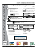
www.multiquip.com parts ordering procedures Ordering parts has never been easier! Choose from three easy options: order via internet (dealers only): Best deal! Effective: January 1st, 2006 If you have an MQ Account, to obtain a Username and Password, E-mail us at: parts@multiquip. com. Order parts on-line using Multiquip’s SmartEquip website! ■ View Parts Diagrams ■ Order Parts ■ Print Specification Information To obtain an MQ Account, contact your District Sales Manager for more information.
Safety Information Do not operate or service the equipment before reading the entire manual. Safety precautions should be followed at all times when operating this equipment. Failure to read and understand the safety messages and operating instructions could result in injury to yourself and others. Potential hazards associated with the operation of this equipment will be referenced with hazard symbols which may appear throughout this manual in conjunction with safety messages.
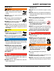
Safety Information general SaFeTy CauTion never operate this equipment without proper protective clothing, shatterproof glasses, respiratory protection, hearing protection, steel-toed boots and other protective devices required by the job or city and state regulations. Avoid wearing jewelry or loose fitting clothes that may snag on the controls or moving parts as this can cause serious injury. never operate this equipment when not feeling well due to fatigue, illness or when under medication.
Safety Information poWer Buggy SaFeTy CauTion danger Engine fuel exhaust gases contain poisonous carbon monoxide. This gas is colorless and odorless, and can cause death if inhaled. The engine of this equipment requires an adequate free flow of cooling air. never operate this equipment in any enclosed or narrow area where free flow of the air is restricted. If the air flow is restricted it will cause injury to people and property and serious damage to the equipment or engine.
Safety Information do noT operate the power buggy at excessive speeds. Reckless operation may cause accidents and severe injury. Slow down when approaching people, wet areas, and going up and down grades. It is the responsibility of the operator to adjust speed, as necessary, depending on the conditions of the road or path. alloW extra time to stop when operating the power buggy ion wet surfaces or loosely graded materials.
Safety Information engine SaFeTy Warning do noT place hands or fingers inside engine compartment when engine is running. never operate the engine with heat shields or guards removed. Keep fingers, hands hair and clothing away from all moving parts to prevent injury. alWayS shut down the engine before performing service or maintenance. do noT remove the engine oil drain plug while the engine is hot.
Safety Information alWayS recharge the battery in a well-ventilated environment to avoid the risk of a dangerous concentration of combustible gases. TranSporTing SaFeTy If the battery liquid (dilute sulfuric acid) comes into contact with clothing or skin, rinse skin or clothing immediately with plenty of water. alWayS shutdown engine before transporting.
specifications Table 1. Specifications (Power Buggy) Models WBH16/WBH16E Wheelbase 44 in. (1,117.6 mm) Overall Length 103 in. (2,616.2 mm) Overall Width- Dual Wheels 43.25 in. (1,098.6 mm) Maximum Weight Capacity 30.25 in. (738.65 mm) 2,500 lbs. (Dual Wheels) (1,136 kg) Overall Width- Single Wheel 32 in. (813 mm) Maximum Weight Capacity 1,100 lbs. (499 kg) (Single Wheel) Overall Height 53 in. (1346.2 mm) Operating Weight 1,200 lbs. (544.2 kg.) Ship Weight Palletized 1,260 lbs. (585 kg.
specifications Table 2. Specifications (Engine) GX390RT2QTT (Recoil Start) Model GX390RT2QNB2 (Electric Start) 3.46 x 2.51 in. Bore X Stroke (88 x 64 mm.) Displacement 389 cc Maximum Power 11.7 hp (3,600 rpm) Maximum Torque 19.5 ft-lbs. (2.7 kg-m) @ 2,500 rpm Compression Ratio 8.0 : 1 Idle Speed 1,400 ± rpm Maximum No Load RPM 3.850 ± rpm 1 gal./hr. Specific Fuel Consumption (3.78 liters/hr.) Fuel Tank Capacity 5.5 gal. (20.81 liters) Crankcase Oil Capacity 1.16 qts. (1.
dimensions Side View rear View Figure 1. WBH16/WBH16E Dimensions WBH16/WBH16E power buggy (S/n 110401 & up)• operation and parts manual — rev.
general information The MQ Whiteman Power Buggy, Models WBH16 (recoil start) and WBH16E (electric start) are intended for the transportation of concrete, concrete spreading and spot pouring. In addition, the WBH16/WBH16E is designed for landscaping applications, material sub-base distribution, job site cleanup and material transport. The Power Buggy is equipped with a 6-inch dump height which provides clearance and enables the operator to maneuver over any form height.
components Figure 2. WBH16/WBH16E Power Buggy Components 1. Tub or Bucket — Used for the transportation of material. Tub holds approximately 16 cubic feet (0.59 cubic yards) of water. 10. Engine — The WBH16 uses a HONDA GX390RT2QTT (recoil start) engine. The WBH16E uses a HONDA GX390RT2QNB2 (electric start) engine. 2. Handle Bar (Steering) — This handle bar is used to steer the buggy. When driving the buggy, use both hands and hold onto both handle bar grips. 11.
basic engine Figure 3. Honda GX390K1 Engine 1. Fuel Filler Cap — Remove this cap to add unleaded gasoline to the fuel tank. Make sure cap is tightened securely. DO NOT over fill. 8. Spark Plugs — Provides spark to the ignition system. Set spark plug gap to 0.70- 0.76 mm (0.028 - 0.030 in.) Clean spark plug once a week. 2. Throttle Lever — Used to adjust engine RPM speed (lever advanced forward - SLOW, lever back toward operator - FAST). 9. Muffler — Used to reduce noise and emissions. 3.
inspection Before Starting 1. Read safety information at the beginning of manual. 2. Clean the machine, removing dirt and dust, particularly the engine cooling air inlet, carburetor and air cleaner. 3. Check the air filter for dirt and dust. If air filter is dirty, replace air filter with a new one. 4. Check carburetor for external dirt and dust. Clean with dry compressed air. 5. Check fastening nuts and bolts for tightness. Engine Oil Check 1.
inspection Parking Brake Check Check the brakes as outlined in the maintenance section of this manual. Linkage Check Check and make sure that all linkages within the buggy are functioning correctly. Steering Check 1. Check and make sure that the power buggy's steering turns freely and that there is no binding. 2. Make sure that the zerk fitting for the steering has been lubricated. Dump Cylinder Check 1. Check the power buggy's dump cylinder as outlined in the operation section of this manual. 2.
OPERATION CAUTION DO NOT attempt to operate the power buggy until the Safety Information, General Information, and Inspection sections of this manual have been read and thoroughly understood. 4. Place the choke lever (Figure 10) in the OPEN position if starting a warm engine or the temperature is warm. ELECTRIC START (WBH16E only) 1. Before attempting to start the power buggy, make sure that the safety kill switch (Figure 19) is not pushed in. The power buggy will not start with the kill switch engaged.
OPERATION 7. Make sure the choke lever is in the OPEN position (Figure 10) before operating the power buggy. Before the buggy is placed into operation, run the engine for several minutes. Check for fuel leaks, and noises that would associate with a loose guard or cover. RECOIL START PRE-CHECK 1. Engage the parking brake lever (Figure 15) and attempt to rock the buggy back and forth. If the wheels turn during the rocking motion, adjust the brakes as outlined in the maintenance section of this manual. 1.
OPERATION Parking Brake/Direction Lever Before the power buggy can be put into operational use, it is best to perform a test run to make certain that all components are functioning properly. 3. When using the buggy for the first time, test the brake. With the right foot, step up and place it on the brake pedal (Figure 18). Gradually apply pressure to the brake pedal until the buggy comes to rest. 1. Place the buggy on flat solid ground. 2. Engage the parking brake lever. 3.
OPERATION EMERGENCY SHUTDOWN CAUTION The WBH16/WBH16E is equipped with a safety kill switch. This switch is located on the right side of the handle bar. 1. Press the power buggy's kill switch (Figure 19) and listen for the engine to stop. DO NOT steer the buggy left or right when traveling up or down on a grade. Travel in a straight path. CAUTION Avoid sudden and quick turns. When steering, turn the handle bar slowly. Always face the controls when traveling. TRAVELING ON A SLOPE 1.
OPERATION 2. When going up or down a slope, always travel in the forward direction (Figure 22). NOTICE Releasing either one (dump control lever or pedal) before dump is completed, will cause the tub to return to the horizontal position. Figure 22. Slope Travel Direction Tub (Bucket) Dumping The hydraulic dump can be controlled by hand (dump control lever) or foot (dump pedal). 1. To activate the hydraulic dump, press down on the dump pedal (Figure 23) or move the dump control lever forward.
maintenance Engine Refer to the Honda engine owner’s manual for specific information. 1. Check engine oil after every 10 hours of operation and maintain proper levels. 2. Drain oil after every 50 hours of operation and refill with grade of oil recommended below: Above 40 °F. (13 °C.) - S.A.E. 30 Below 40 °F. (13 °C.) - S.A.E. 20 5. Replace hydraulic oil after every 200 hours of operation. The hydraulic oil filter should be changed each time the hydraulic oil is changed.
maintenance pump control lever adjustment Table 4. Tire Wear Troubleshooting If the power buggy tends to creep in the forward or reverse direction after you release the speed control lever, the pump control lever requires adjustment. 3. Place the machines drive wheels on jacks or blocks free from ground contact. 4. Locate the pump control lever adjusting bolt. 5. Loosen the jam nut. 6.
troubleshooting Troubleshooting (power Buggy) Symptom possible problem Solution Speed control cable out of adjustment? Adjust speed control cable. Replace cable if necessary Hydraulic oil level low.? Check hydraulic oil level. Add oil if necessary. Contaminated hydraulic oil filter? Replace hydraulic oil filter. Low engine RPM? Check engine speed. Forward/Reverse lever in neutral position? Place lever in either forward or reverse position. Check hydraulic motors.
troubleshooting Troubleshooting (engine) Symptom possible problem Solution Spark plug bridging? Check gap, insulation or replace spark plug. Carbon deposit on spark plug? Clean or replace spark plug. Short circuit due to deficient spark plug insulation? Check spark plug insulation, replace if worn. Improper spark plug gap? Set to proper gap. Fuel reaching carburetor? Check fuel line. Water in fuel tank? Flush or replace fuel tank. Fuel filter clogged? Replace fuel filter.
troubleshooting Troubleshooting (engine) - continued Symptom Weak in power, compression is proper and does not misfire. Weak in power, compression is proper but misfires. Engine overheats. Rotational speed fluctuates. Recoil starter malfunctions. (if applicable) Starter malfunctions. possible problem Air cleaner dirty? Clean or replace air cleaner. Improper level in carburetor? Check float adjustment, rebuild carburetor. Defective spark plug? Clean or replace spark plug.
hydraulic system diagram WBH16/WBH16E power buggy (S/n 110401 & up)• operation and parts manual — rev.
Explanation of Code in Remarks Column The following section explains the different symbols and remarks used in the Parts section of this manual. Use the help numbers found on the back page of the manual if there are any questions. NOTICE The contents and part numbers listed in the parts section are subject to change without notice. Multiquip does not guarantee the availability of the parts listed. Sample parTS liST no. 1 2% 2% 3 4 parT no. parT name qTy. remarKS 12345 BOLT .....................1 .....
Suggested Spare Parts WBH16/WBH16E power buggy with honda GX390RT2QTT/GX390RT2QNB2 engine 1 to 3 units Qty. P/N Description 1............508667...................FILTER, HYDRAULIC OIL 1............16477.....................CAP, HYDRAULIC OIL TANK 1............18035.....................PUMP, HYDROSTATIC 1............511719...................COUPLING, ENGINE SHAFT 2............18316.....................LINING, BRAKE 1............18145.....................ROD, BRAKE CONTROL 1............520820.................
nameplate and decals 6 18247 TRAVEL NEUTRAL LIFT 9 513608 12 4 LIFT 18245 5 WARNING! 2 HOT SURFACE AREA 18248 WBH16 LIFT 7 4 1 10 513608 11 MQ WHITEMAN SAFETY INSTRUCTIONS OPERATE AT SAFE SPEEDS ONLY READ OPERATOR’S MANUAL BEFORE STARTING PLACE IN NEUTRAL BEFORE STARTING NO UNAUTHORIZED/UNTRAINED OPERATORS NO RIDERS BE SURE ALL SAFETY DEVICES ARE OPERATIONAL AND IN PLACE BEFORE STARTING THE ENGINE DISCONNECT SPARK PLUG BEFORE SERVICE NEVER OPERATE IN AN ENCLOSED AREA NEVER LEAVE UNATT
nameplate and decals NO. PART NO. 1 18252 2 18251 3 EM985 4 513608 5 18245 6 18247 7 18248 8 9 10 11 12 PART NAME QTY. REMARKS DECAL, WBH16 2 DECAL, MQ WHITEMAN 2 DECAL, HYDRAULIC OIL 1 DECAL, LIFTING HOOK 3 DECAL, FORKLIFT LIFTING 6 DECAL, CRUSH WARNING 1 DECAL, HOT SURFACE WARNING 1 DECAL, BUCKET DUMP LEVER.......................1................NOT AVAILABLE* DECAL, TRAVEL LEVER DIRECTION...............1................NOT AVAILABLE* DECAL, WHITEMAN SAFETY INSTRUCTIONS.....1................
HYDRAULIC DRIVE ASSY. 25 VIEW FROM OPERATOR’S PLATFORM 2 24 30 SEAL KIT 1 4 23 4 16 19 22 5 6 22 6 17 19 18 LEFT DRIVE MOTOR RIGHT DRIVE MOTOR 16 13 21 20 8 26 18 10 15 17 14 9 7 12 11 8 page 34 — WBH16/WBH16E power buggy (S/n 110401 & up) • operation and partsmanual — rev.
HYDRAULIC DRIVE ASSY. NO. 1 2 4 5 6 7 8 9* 10* 11 12 13 14 15 16 17 18 19 20 21 22 23 24 25 26 30 PART NO. 18058 18264M 511810 18276M 512189 492527 18029 511692 18237 492584 18190 491689 PT018038 18040 3365 505718 18011 PE449105 492600 6109180 18027 18275M 18265M 3322 516528 18011K PART NAME QTY. REMARKS VALVE, DIRECTION CONTROL 1 HOSE, DIRECTION VALVE TO DRV. MOTOR 1 ADAPTER, ELBOW 2 HOSE, LH HYDRAULIC MOTOR 1 ADAPTER, T - CONNECTOR 2 NUT, HEX 1/2-20 8 WHEEL, DRIVE ASSY.
HYDRAULIC PUMP ASSY. 1 16 15 3 17 2 13 3 2 SEE DRIVE ASSY. 4 5 12 DIRECTION VALVE 14 6 7 13 LIC U RA NK D HY IL TA O SEE HYDRAULIC OIL TANK ASSY. 11 12 8 8 HYDRAULIC OIL FILTER 10 9 SEE DUMP CYLINDER ASSY. DUMP VALVE page 36 — WBH16/WBH16E power buggy (S/n 110401 & up) • operation and partsmanual — rev.
HYDRAULIC PUMP ASSY. NO. 1 2 3 4 5 6 7 8 9 10 11 12 13 14 15 16 17 PART NO.
HYDRAULIC DUMP ASSY. 2 3 CONNECT TO HYDRAULIC PUMP ASSY ITEM 9 1 4 5 3 6 4 2 CONNECT TO HYDRAULIC PUMP ASSY ITEM 4 7 DUMP VALVE 9 page 38 — WBH16/WBH16E power buggy (S/n 110401 & up) • operation and partsmanual — rev.
HYDRAULIC DUMP ASSY. NO. 1 2 3 4 5 6 7 9 PART NO. PART NAME 18022 CYLINDER, HYDRAULIC DUMP 491705 ZERK FITTING 511803 ADAPTER, ELBOW 18020 HOSE, DUMP VALVE TO HYD. PISTON 511804 ADAPTER, STRAIGHT 512234 ADAPTER, ELBOW 511806 ADAPTER, STRAIGHT 506191 ADAPTER, ELBOW QTY. 1 2 2 2 2 1 1 1 REMARKS WBH16/WBH16E power buggy (S/n 110401 & up)• operation and parts manual — rev.
PUMP AND COUPLING ASSY. 1 Engine 24 21 23 2 6 20 28 7 29 22 27 26 25 11 HYDRAULIC PUMP 4 7 6 FRAME page 40 — WBH16/WBH16E power buggy (S/n 110401 & up) • operation and partsmanual — rev.
PUMP AND COUPLING ASSY. NO. 1 2 4 6 7 11 20 21 22 23 24 25 26 27 28 29 PART NO. 492472 511719 18112 492596 492355 506250 512494 512493 512505 492373 492624 512367 492595 492621 492438 492623 PART NAME SCREW, ALLEN HEAD 3/8-16 X 3/4 COUPLING, ENGINE SHAFT FAN WASHER, FLAT 1/4" SCREW, HHC 1/4-20 X 1/2 KEY, WOODRUFF FAN GUARD BRACKET, LONG BRACKET, SHORT BOLT, C/H 3/8" NC X 3/4" G5 WASHER, LOCK 3/8 IN. BOLT, C/H 3/16" NC X 1/2" G2 WASHER, FLAT 3/16 IN. WASHER, LOCK 3/16 IN.
TUB ASSY. 2 3 1 5 14 DASHED ( ) ITEMS ARE LOCATED ON THE UNDERSIDE OF THE BASE PLATE 6 15 4 15 5 5 13 12 11 10 7 9 LOCATED ON THE BACKSIDE OF COUNTERWEIGHT 5 6 page 42 — WBH16/WBH16E power buggy (S/n 110401 & up) • operation and partsmanual — rev.
TUB ASSY. NO. 1 2 3 4 5 6 7 9 10 11 12 13 14 15 PART NO. PART NAME 18004 TUB, PLASTIC 492313 SCREW, HHC 3/8-16 X 1-1/2 512193 WASHER, FLAT 3/8 LARGE 492598 WASHER, FLAT 3/8 490957 RING, SNAP 18130 PIN, HYD. PISTON CROSS 18129 PIN, TUB FRAME CROSS 492365 SCREW, HHC 5/16-18 X 1-1/4 492597 WASHER, FLAT 9.5 X 22.2 492583 NUT, NYLOC 3/4-16 492582 NUT, NYLOC 5/16-18 512279 SUPPORT, BUM STOP 18099 FRAME, TUB MOUNT 491705 ZERK GREASE FITTING QTY.
PANEL ASSY. 11 1 12 10 13 5 3 8 2 12 5 5 4 6 8 7 5 5 8 9 page 44 — WBH16/WBH16E power buggy (S/n 110401 & up) • operation and partsmanual — rev.
PANEL ASSY. NO. 1 2 3 4 5 6 7 8 9 10 11 12 13 PART NO. 503978 511474 18008 492355 492597 18141 492364 492582 801026 492623 505401 492363 23297 PART NAME POP RIVET AM-56 FASTENER, ACCESS DOOR DOOR, ACCESS SCREW, 1/4 NC X 1/2 IN. G5 WASHER, FLAT 9.5X22.2 COVER, R/SIDE ENGINE SCREW, HHC 5/16-18X1 NUT, NYLOC 5/16-18 COVER, L/SIDE ENGINE WASHER, LOCK 5/16 SCREW, HHC 5/16-18X 1/2 SCREW, HHC 5/16 NC X 3/4 G5 MANUAL HOLDER QTY.
BRAKE ASSY. page 46 — WBH16/WBH16E power buggy (S/n 110401 & up) • operation and partsmanual — rev.
BRAKE ASSY. NO. 1 2 3 4 5 6 7 8* 9* 10* 11* 12 13 14 15 16 17 18 19 20 21 22 23 24 25 26 PART NO. 511762 511698 511761 18111 492600 492584 18167 18307 18300 18316 503723 18303 492395 18302 18032 18314 492582 492303 505170 18016 492367 18015 492597 18145 512881 492600 PART NAME QTY. REMARKS SCREW, HHC 1/2-13X8 1 CLEVIS, ASSY.
sTEERING ASSY. 37 37 page 48 — WBH16/WBH16E power buggy (S/n 110401 & up) • operation and partsmanual — rev.
sTEERING ASSY. NO. 1 2 3 4 5 6 7 8 9 10 11 12 13 14 15 16 17 18 19 20 21 22 23 24 25 26 27 28 29 30 31 32 33 34 35# 36# 37 PART NO. 18132 492581 492582 491030 504505 18025 18242 511432 18181 18177 511717 18061 512414 492561 492584 492357 18183 18176 18182 18133 492465 506088 492369 491723 18238 512186 18091 EM941306 EM501299 512210 491688 18049 8115 511159 EM903113 15191VB 512200 PART NAME QTY.
chassis ASSY. 3 2 2 2 11 4 6 5 10 7 9 1 8 2 12 13 14 26 25 1 27 15 28 24 17 23 22 14 18 19 2 1 20 16 2 1 21 page 50 — WBH16/WBH16E power buggy (S/n 110401 & up) • operation and partsmanual — rev.
chassis ASSY. NO. PART NO. PART NAME QTY. REMARKS 1 492583 NUT, NYLOC 3/8 10 2 492598 WASHER, FLAT 3/8 18 3 492313 SCREW, HHC 3/8 - 16 X 1-1/2 3 4 503112 SCREW, HHC 3/8 - 16 X 2-3/4 4 5 492375 SCREW, HHC 3/8 - 16 X 12 2 6 492357 SCREW, HHC 1/4 - 20 X 12 2 7 492622 WASHER, LOCK 1/4 2 8 512196 BRACKET, HYD.
dump pedal and handle ASSY. 3 1 4 2 5 6 7 17 9 8 15 19 16 15 16 18 13 12 14 12 10 11 page 52 — WBH16/WBH16E power buggy (S/n 110401 & up) • operation and partsmanual — rev.
dump pedal and handle ASSY. NO. PART NO. 1 492401 2 512184 3 18121 4 18065 5 512185 6 492622 7 512183 8 18064 9* 10 492596 11 492581 12 492584 13 492600 14 18152 15 18123 16 511761 17 18153 18 492400 19 18122 PART NAME QTY. REMARKS SCREW, HHC 1/2- 13 X 4 1 NUT, NYLOC 3/16- 24 1 KNOB, LEVER 1 LEVER, DUMP VALVE 1 SCREW, HHC 1/4- 20 X1- 3/4 2 WASHER, LOCK 1/4 1 SCREW, HHC 3/16- 24 X1- 1/4 1 VALVE, DUMP....................................................1................
HYDRAULIC OIL TANK ASSY. 2 1 3 11 4 5 10 8 9 6 7 page 54 — WBH16/WBH16E power buggy (S/n 110401 & up) • operation and partsmanual — rev.
HYDRAULIC OIL TANK ASSY. NO. 1 2 3 4 5 6 7 8 9 10 11 PART NO. 3336 16477 18113 492375 491212 492598 492583 49123 492373 492624 18229 PART NAME SIGHT GAUGE, HYD. OIL TANK CAP, HYD. OIL TANK TANK HYD. OIL SCREW, HHC 3/8- 16 X1 PLUG, HYD. OIL TANK 1/2’’ WASHER, FLAT 3/8 NUT, NYLOC 3/8- 16 PLUG, HYD. OIL TANK 3/4 SCREW, HHC 3/8- 16 X 3/4 WASHER, LOCK 3/8 SCREEN, OIL RESERVOIR QTY. 1 1 1 3 1 3 3 1 2 2 2 REMARKS WBH16/WBH16E power buggy (S/n 110401 & up)• operation and parts manual — rev.
battery ASSY. (electric start) 2 14 20 18 12 10 8 6 4 16 22 page 56 — WBH16/WBH16E power buggy (S/n 110401 & up) • operation and partsmanual — rev.
battery ASSY. (electric start) NO. 2 4 6 8 10 12 14 16 18 20 22 24 PART NO. 505500 512557 511250 512555 492596 492622 492595 508480 503118 503119 512585 4671 PART NAME WINGNUT BATTERY CABLE, NEGATIVE BATTERY CABLE, POSITIVE BATTERY SUPPORT BRACKET WASHER, FLAT 1/4" WASHER, LOCK 1/4" WASHER, FLAT 3/16" BATTERY SUPPORT PLATFORM BOLT 3/16" x 1" NUT 3/16" SUPPORT BRACKET BOLT BATTERY QTY. 2 1 1 1 2 2 4 1 2 2 2 1 REMARKS WBH16/WBH16E power buggy (S/n 110401 & up)• operation and parts manual — rev.
fuel assy. 5 2 3 1 16 3 15 1 2 25 19 18 3/16” 5/16” Left Side Engine Cover 22 20 TO ENGINE AIR FILTER 21 7 20 11 1/4” 23 17 7 12 23 TO ENGINE CARBURETOR 9 7 10 7 11 1 1/4” 24 14 page 58 — WBH16/WBH16E power buggy (S/n 110401 & up) • operation and partsmanual — rev.
fuel assy. NO. 1 2 3 5 7 9 10 11 12 14 15 16 17 18 19 20 21 22 23 24 25 PART NO. 492622 492356 509161 520820 506208 19633 20795 60013 20763 511807 515386 800845 800841 23507 23508 517621 60004 23505 510725 492355 60028 PART NAME WASHER, LOCK 1/4 IN. SCREW, 1/4 x 3/4 IN. G5 WASHER, FLAT 1/4 IN.
engine assy. 15 Fuse 23 22 6 5 20 16 2 6 14 Regulator 17 19 25 24 5 9 3 7 8 4 MODEL WBH16E ONLY 1 14 10 12 13 11 14 13 page 60 — WBH16/WBH16E power buggy (S/n 110401 & up) • operation and partsmanual — rev.
engine assy. NO. 1 1 2 3 4 5 6 7 8 9 10 11 12 13 14 15 16 17 19 20 22 23 24 25 PART NO. GX390RT2QTT GX390RT2QNB2 801029 503118 512512 492595 503119 512507 508998 18007 492583 492598 492313 492581 492596 492356 492358 801019 10958 800921 492621 503115 801014 11078 PART NAME QTY.
Terms and Conditions of Sale — Parts paymenT TermS 5. Parts must be in new and resalable condition, in the original Multiquip package (if any), and with Multiquip part numbers clearly marked. 6. The following items are not returnable: Multiquip reserves the right to quote and sell direct to Government agencies, and to Original Equipment Manufacturer accounts who use our products as integral parts of their own products. a. SpeCial eXpediTing ServiCe Terms of payment for parts are net 30 days.
notes WBH16/WBH16E power buggy (S/n 110401 & up)• operation and parts manual — rev.
Operation and parts Manual HERE’S HOW TO GET HELP PLEASE HAVE THE MODEL AND SERIAL NUMBER ON-HAND WHEN CALLING United StateS Multiquip Corporate Office 18910 Wilmington Ave. Carson, CA 90746 Contact: mq@multiquip.com MQ Parts Department Tel.