SP-6065 Concrete Saw Operation Manual Revision #0 (04/23/03)
FOR HELP & INFORMATION CONTACT MULTIQUIP Please have the Model and Serial Number on-hand when calling. MAIN (M-F 7AM-5PM) (PACIFIC STANDARD TIME) PARTS DEPARTMENT SERVICE DEPARTMENT/ TECHNICAL ASSISTANCE MULTIQUIP INC. 18910 WILMINGTION AVE. CARSON, CALIFORNIA 90746 800-421-1244 or 310-537-3700 800-427-1244 or 310-537-3700 FAX: 800-672-7877 or 310-637-3284 800-428-1244 or 310-537-3700 FAX: 310-537-1173 WARRANTY DEPARTMENT 888-661-4279 or 310-661-4279 FAX: 310-537-1173 2 E-MAIL Mq@multiquip.
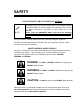
Conventions Throughout this manual, the following conventions are used to indicate important information. ! NOTE Text set off like this presents clarifying information, specific instructions, commentary, sidelights, or interesting points of information. Text set off like this indicates that failure to follow directions could result in damage to equipment. CAUTION Text set off like this indicates that failure to follow directions could result in bodily harm or loss of life.
WARNING CALIFORNIA – Proposition 65 Warning Engine exhaust and some of its constituents, and some dust created by power sanding, sawing, grinding, drilling and other construction activities contain chemicals known to the State of California to cause cancer, birth defects and other reproductive harm. Some examples of these chemicals are: o o o o Lead from lead-based paints. Crystalline silica from brick. Cement and other masonry products. Arsenic and chromium from chemically treated lumber.
TABLE OF CONTENTS CONVENTIONS...................................................................................................................3 SAFETY..............................................................................................................................7 OPERATION ...................................................................................................................19 BEFORE STARTING ........................................................................................
MAINTENANCE.............................................................................................................41 REMOVABLE GUARDS AND ACCESS PANELS ...................................................................41 BELTS AND PULLEYS ......................................................................................................42 V-Belt Tension............................................................................................................
SAFETY FOR YOUR SAFETY AND THE SAFETY OF OTHERS! ! NOTE This Owner's Manual has been developed to provide complete instructions for the safe and efficient operation of the Multiquip SP-6065 CONCRETE SAW. For engine maintenance information, please refer to the engine manufacturers instructions for data relative to its safe operation. Before using this CONCRETE SAW, ensure that the operating individual has read and understands all instructions in this manual.
HAZARD SYMBOLS Lethal Exhaust Gases Engine exhaust gases contain poisonous carbon monoxide gas is colorless and odorless, and can cause death if inhaled. NEVER operate this equipment in a confined area or structure that does not provide ample free flow air. Explosive Fuel Motor fuels are highly flammable, and can be dangerous if mishandled. DO NOT start the engine near spilled fuel or combustible fluids. DO NOT fill the fuel tank while the engine is running or hot.
Guards and Covers NEVER operate the saw without blade guards and covers in place. Adhere to safety guidelines ANSI American National Standards Institute, OSHA or other applicable local regulations. Rotating Blades Rotating blade can cut and crush. Keep hands and feet clear. Respiratory Hazard ALWAYS wear approved respiratory protection. Sight and Hearing Hazard ALWAYS wear approved eye and hearing protection.
Skin Injection Hazard NEVER use your hand to find hydraulic leaks. Use a piece of wood or cardboard. Hydraulic fluid injected into the skin must be treated by a knowledgeable physician immediately or severe injury or death can occur. Over Speed Conditions NEVER tamper with the factory settings of the engine governor or engine settings. Personal injury and damage to the engine or equipment can result if operating in speed ranges above maximum allowable.
RULES FOR SAFE OPERATION Most accidents involving product operation, maintenance and repair are caused by failure to observe basic safety rules and precautions. Accidents can often be avoided by recognizing potentially hazardous situations before an incident occurs. General Safety Warnings § DO NOT operate or service this equipment before reading this entire manual. Failure to follow instructions may lead to serious injury or death.
§ Before operating the saw, make sure all protective guards are securely in place. All saws are supplied with a blade guard, collar guard and belt guard. § Whenever necessary, replace operation and safety decals if they become difficult to read. § Verify the engine start switch is set to the OFF position before installing a blade. § Make sure the operator knows how to turn the engine OFF in case of an emergency. § Do not go near rotating parts (blades, belts, pulleys or wheels) while engine is running.
General Safety Precautions § ALWAYS read, understand, and follow procedures in the Operator’s Manual before attempting to operate the equipment. § Be sure the operator is familiar with proper safety precautions and operating techniques before using the saw. § Make sure the operating area is clear before starting the engine. § Maintain this equipment in a safe operating condition at all times. § Keep the saw clean. It will work better and last longer.
BLADE SAFETY § ALWAYS inspect diamond blades before each use. The blade should exhibit no cracks, dings, or flaws in the steel centered core and/or rim. Center (arbor) hole must be undamaged and true. § Examine blade flanges for damage, excessive wear and cleanliness before mounting blade. Blade should fit snugly on the shaft and against the inside/outside of the saw. WARNING § Only cut the material that is specified by the blade.
SAW TRANSPORTATION SAFETY § Use appropriate lifting equipment to ensure the safe movement of the saw. § DO NOT use the handle bars and/or front pointer as lifting points. CAUTION § NEVER attempt to tow the untrailered saw behind a vehicle. § NEVER transport the saw with the blade mounted. EMERGENCIES § ALWAYS know the location of the nearest fire extinguisher. § ALWAYS know the location of the nearest first aid kit.
MACHINE OPERATION AND SAFETY DECALS The Multiquip SP-6065 Saw is equipped with a number of operation and safety decals. Should any of these decals become unreadable, replacements can be obtained from your dealer. WARNING P/N 15582 P/N 15580 KEEP FEET CLEAR P/N 25250-001 WARNING! KEEP HANDS CLEAR P/N 25249-001 P/N 15581 CAUTION When Larger Blade and Guard is Installed, Belt Drive MUST Be Changed to Proper Size. See Owners Manual.
Serial Tag Fig. 1 — Serial Tag ! For future reference, fill in the model number and serial number of your saw in the spaces on the label above. NOTE The serial tag contains the model number and serial number of the saw. This information details all parts that were included with the saw when it was shipped from the factory, as well as the date of manufacture. Record your ENGINE model, specification number and serial number here: MODEL NO. SPEC. NO. SERIAL NO.
SERIAL TAG ENGINE SERIAL NUMBERS Fig. 2 — Serial Number Locations ! NOTE 18 § The 5/8” blade-mounting bolt on the right side of the saw (as viewed from the operator’s position) has a left hand thread, while the blade-mounting bolt on the left side of the saw has a right hand thread. § Most saw hardware is measured in English (inch) units. The Illustrated Parts List notes any Metric hardware. Be sure to use the correct hardware and proper tools.
OPERATION Before Starting Before starting the saw, carefully follow the checklist below: r Securely install the Belt Guard (2). r Fully slide on the Collar Guard (3). r Verify that proper-sized Blade Guard (4) is fully installed on the Blade Guard mounting tab. r Confirm the rear and side access panels (5) & (6) and engine protector are in place. r Wear eye and hearing protection and protective clothing. r Adjust handle bars (1) for best operator control.
Engine Power, Cutting Power & Sheave Size The cutting capability of your saw is a relationship between engine power (as reflected in the engine RPM) and the speed (RPM) of the Blade Shaft. The gasoline engine of the SP-6065 runs at 2800 RPM (full load). If 2800 RPM was a desirable Blade Shaft speed for the average conditions in which you work, we would use the same size sheave on the engine shaft and the Blade Shaft; and the ratio between the two would be 1 : 1. 1:1 Blade Shaft 1.
Typically, however, the ratios are not used to design a level of torque; they are used to create a saw with the optimum blade speed (blade Shaft RPM) for you. The major factors are: ♦ diameter of blade(s) you commonly use, and ♦ cutting conditions you work under We can also tailor the Blade Shaft RPM (blade speed) by adjusting the “primary” ratio between the engine and the Blade Shaft.
Blade RPM vs. Surface Feet Per Minute (SFPM) When choosing a blade for your cutting conditions, follow the blade manufacturer’s recommendations. Match the blade speed (Blade Shaft RPM) to the recommended blade Surface Feet Per Minute (SFPM). SFPM 12” 14” 16” 18” 20” 24” 26” 30” 36” diam. RPM diam. RPM diam. RPM diam. RPM diam. RPM diam. RPM diam. RPM diam. RPM diam.
Installing the Blade The blade can be mounted on either side of the saw to accommodate different cutting jobs. 1. Raise the saw so that the blade will clear the ground when installed. 2. Verify that blade collars are clean and undamaged. 3. Insert the bushing and mounting bolt through the outer collar and blade. ♦ Align collar pin through the blade into the inner collar. 4. Tighten the 5/8” mounting bolt to 125-175 foot-pounds of torque.
Stacking Blades for Wide Cuts WARNING NEVER attempt to stack blades beyond the capacity of the Kits described here. NEVER operate the saw without blade guards in place. Combining (stacking) blades together to make wide cuts requires an optional Bushing Extension Kit. • Kit #18501 allows blade stacking from .375” to .75” thickness. • Kit #18502 allows blade stacking from .75” to 1.125” thickness. The kits consist of an outer collar with a longer pin, an extended bushing, and longer bolts. 1.
Installing and Removing the Blade Guard Blade Guards are “ambidextrous” – that is, they can be installed on either side of the saw. Installing the Blade Guard 1. Slide the Blade Guard Mounting Clip onto the Guard Mounting Tab on the frame. 2. Connect the water delivery hose to the Blade Guard. ♦ Ensure that the water pipes are pointed toward the water distribution grooves in the Blade Collars. 3. Make sure the front-hinged section of the Blade Guard is fully closed before use.
Blade Guard Water Supply Verify that the water hose on the saw is connected to the Blade Guard and that the water pipes are pointed into both Blade Collars. CAUTION Make sure that the 90º outlets of the water tubes point toward the lower portion of the blade collars, aimed at the delivery ports, for proper water delivery to the blade. Water Tube bracket Water Tube aimed at groove in Blade Collar Blade Collar Fig.
Installing the Collar Guard The Collar Guard protects unused Blade Collars. 1. Slide the Collar Guard (1) onto the Guard Mounting Tab on the frame. 2. Verify that the unused Blade Collar (2) is secured to the Blade Shaft, by tightening the mounting bolt (3). Collar Guard Mounting Bolt Collar Fig.
Water Supply and Control § To prevent damage to the impeller of a belt driven water pump, do not run the engine with the water pump switch on, unless the water supply is connected and water is flowing. CAUTION § When storing the saw during freezing weather, blow out the water lines to prevent damage to the water delivery system. 1. Connect the water supply hose to the water inlet (garden hose) fitting (1) on the left side of the saw. 2.
Control Panel Ignition Switch ON-OFF Depth Indicator Light Switch Drive Disengage Voltmeter Choke Engine Status Indicator Throttle Pointer Cable Cam Cleat Auxiliary Switch Blade shaft Tachometer Raise Button Depth Stop Valve Maintenance Information Plunge Button Water Flow Control Water ON/OFF Control Valve Water Pump Switch (Option) Fig.
Handlebars The handlebars are adjustable to three different angles, for optimum operator control, and can also be slid fully inward for storage. Once handlebars are adjusted, lock them into position by tightening the lock knob on each side. Lock Knob P3 P2 P1 Three operating positions Storage position Fig.
Fueling the Saw The saw features a 10-gallon, clear, molded plastic fuel tank with a sight gauge, central drain, and shutoff valve. The gas tank cap is located at the front of the control console. CAUTION § § § § § Be sure the engine is turned off prior to fueling the saw. Do not spill fuel on control panel or engine. Wipe up spills immediately Do not over-tighten gas cap. Use unleaded gasoline only. Fuel Tank Cap Sight Gauge Shut-off Valve Fig.
Starting and Stopping the Engine Do not leave the saw unattended while the engine is running. Do not start, park, or leave the saw unattended on a slope. If the saw has an optional water pump, do not run the saw dry with the water pump switch ON — otherwise the pump impellers will be damaged. § In normal operation, Do not stop the engine abruptly when hot! Reduce the throttle to idle and allow the engine to run one or two minutes before turning the ignition switch off. § § § CAUTION 1.
Block Heaters Optional Block Heaters, (installed directly on the crankcase), are operated by plugging them into an electrical outlet via an extension cord. Do not use when low temperatures are above 20°F. The block heater is NOT thermostatically controlled and should be used only prior to intended use of saw. CAUTION § Do not leave optional Block Heaters plugged in unattended, for extended periods or when temperatures are above 20°F.
6 5 4 3 2 1 Fig.
Raise — Lower Controls This saw uses a 12-volt hydraulic pump and cylinder to raise and lower the blade. The SP 6065 saw has a plunge button and a raise button. Controls are located on the joystick handle. Fig. 16 — Joystick Handle - Controls 1. To lower the blade to the cut, push the button on the end of the handle (1). 2. To lift the blade, hold down the Raise button on the side of the handle (3).
Setting the Depth Stop This saw uses a hydraulic Depth Stop to position and lock the blade at the desired cut depth. 1. With the blade raised several inches off the ground, open the Depth Stop Valve to allow the cylinder to “pump out”. 2. Close the Depth Stop Valve. The system is now “preloaded” and ready to complete setting the desired cutting depth. 3.
Drive System This saw has a cable-controlled Hydro-Gear hydrostatic powered transaxle with infinite F-N-R speed adjustment via a joystick controller. The saw is designed with locked axle drive, and can travel at speeds up to 300 feet per minute. Drive System Controls The panel-mounted joystick controls FORWARD-NEUTRAL-REVERSE (F-N-R) and infinitely variable speeds in both directions. To increase forward speed, slowly move the joystick FORWARD.
Transaxle The Hydro-Gear hydrostatic-powered transaxle has no chains, sprockets or open gears to service. There is a simple cable control. The remote filter promotes long life and easy maintenance. Drain Plug Fig.
Night Light The night light can be used on either side of the saw, and can be extended and rotated for best illumination of the cutting area. Aim the light, then lock it in position by tightening the lock knobs. The light can be removed for storage by loosening the lock knobs, disconnecting the light cord and sliding the light bar out of the saw. Lock Knob Lock Knob Fig.
Lift Point The convenient single point for lifting the saw with a hoist is located just in front of the console, between it and the engine. Lift Point Fig. 22 — Lift Point WARNING 40 § To avoid possible injury, stay clear of the saw while it is being hoisted. § To avoid possible damage to the saw, use approved rigging (minimum 2000 lb. test) when hoisting the saw.
MAINTENANCE This saw has many service-saving features, such as fully enclosed oil bath lubricated Blade Shaft bearings, which require no daily lubrication. ! Level the saw frame surface prior to service to get accurate oil level readings.
Belts and Pulleys Belt Qty Part Number Blade Shaft Drive Belt 2 Part # 520009 Jackshaft Belt 1 Part # 521012 Transaxle Drive Belt 1 Part# 521004 Water Pump Option Belts 1 Part# 521006 Part# 521008 Jackshaft Transaxle Drive Belt Blade Shaft Belt Jackshaft Belt Belt Tensioner Pulley Fig. 24 — Belt Locations V-Belt Tension Ideal V-Belt tension is the lowest tension at which the belt will not slip under peak load conditions.
Adjusting Blade Shaft Drive Belt Tension ! NOTE When tightening or loosening drive belts, raise the saw to reduce stress on the tensioning system, and gravity will assist you by pulling the engine backwards slightly. 1. Access the Panel on the side of the saw, loosen the Engine Mount Lock Bolts to allow the engine to rotate forward. ♦ Requires 15/16” socket, 10”- 12” extension and ratchet or breaker bar. Lock Bolt Access Panel Engine Mount Lock Bolt Engine Mount Lock Bolt Fig.
2. Loosen the jam nut on the Single Point Belt Tension Bolt. Single Point Belt Tension Bolt Jam Nut Fig. 26— Single Point Belt Tension Bolt 3. Adjust drive belt to the desired tension. DO NOT over tighten. 4. Tighten the Engine Mount Lock Bolt. 5. Turn the Single Point Tension Bolt until the head of the bolt no longer touches the frame. Tighten the jam nut to prevent the bolt from turning. Replacing the Blade Shaft Belt: See Fig. 25 & 26, above… 1.
Rotary Belt Tensioner The Rotary Belt Tensioner system uses a 3/4”-headed bolt and a 15/16” or 1” nut to set belt tension by positioning an arm between the Tensioner Pulley and the Tensioner Base. Ridges on the Base mark the amount of tension. 1. Loosen the Bolt Head. 2. Rotate the Tensioner Nut clockwise until the desired belt tension is achieved. 3. Tighten the Bolt Head. 4. DO NOT OVER-TIGHTEN.
Blade Shaft Maintenance The fully enclosed Blade Shaft eliminates most maintenance. However, should the Blade Shaft need service or repair, contact Multiquip for details. Fig. 28 — Blade Shaft Blade Shaft Replacement To assure correct Blade Shaft/Wheel alignment it is recommended that this operation be performed by a Multiquip Authorized Service Center.
Blade Collar Removal/Installation Correct removal or installation of the Inner Blade Collar or Flange requires the Collar Puller (option Part Number 18503) shown in Figure 31. WARNING Follow instructions closely to prevent injury from flying Blade Collars! Because of the tapered fit between Blade Collar and Blade Shaft, 5-10 tons of force is needed to release the inner collar. Parts and tools can become dangerous projectiles if instructions are not followed properly. Fig.
Installing the Inner Blade Collar 1. Ensure that the tapered portion of the Blade Shaft, and the Inner Blade Collar are perfectly clean and free of burrs or indentations. Clean and repair as necessary 2. Ensure that the Drive Key is in place. 3. Slide the Inner Collar onto the tapered portion of the Blade Shaft ♦ DO NOT use any lubricant! Lubricant prevents the tapered surfaces of the Collar and Shaft from mating properly. 4. Install the Outer Blade Collar, Collar Bushing, and Mounting Bolt.
5. Loosen the Mounting Bolt and remove the Outer Collar and Bushing. 6. Inspect the Inner Collar to ensure the proper seating of the tapered fit. ♦ The Inner Collar should be seated between .030” and 0.0” (flush) to the end of the Blade Shaft. Inner Collar Blade Shaft Fig. 31 — Proper seating of the Inner Collar on the Blade Shaft 7. Test to ensure that the Inner Collar does not wobble when rotated. Use an indicator dial on the face of the Collar. Maximum tolerance is .
Circuit Breakers Three thermal circuit breakers are located inside the top of the Console. Remove Panel to access circuit breakers Fig. 32 — Circuit Breaker location Under normal circumstances circuit breakers do not require service; they are automatically re-set when an overload condition is corrected. If a breaker is cycling on/off, locate the cause of the electrical overload and repair as required. Maximum Cut Depth Adjustment This saw comes factory-adjusted for maximum usable cut depth.
Lubrication This saw has five grease fittings on the front axle assembly. • Front axle pivot bearings (F1 & F3) • Hydraulic lift cylinder ends (F2, and far end of cylinder) • Depth Stop Pivot Plate (F4) These fittings are easily accessed by raising the saw half way up, and then lifting the rear of the saw until the blade collars rest on the ground. To prevent the possibility of crush injury, ensure that the saw is securely placed on blocks before servicing the lubrication points.
Engine The Model SP-6065 features a xx HP xx gasoline engine. See the engine manual for service details and oil recommendations. • Check air filters daily, replace as required. • Check engine oil level daily. • ♦ Level the frame prior to service to get an accurate reading. ♦ Do Not over-fill with oil. Change engine oil and filter every 50 hours of operation Safety Air Filters are not intended to be used for primary air filtration.
PTO Drive Maintenance Disassembly of the PTO Drive and replacement of the PTO Drive Sheave/Bearing Assembly requires the PTO Bearing Puller (P/N 18610). The Sheave/Bearing Assembly is not serviceable and must be replaced as a complete unit. 1. Remove the Drive Belt (see Replacing the Blade Shaft Drive Belt). 2. Remove the Drive Plate Assembly from the engine. ♦ The Assembly is held on by 11 bolts. ♦ Note the clocking orientation of the plate. 3.
Fig. 36 — PTO Drive Sheave/Bearing Assembly Re-Assembling the PTO Drive 1. Clean and inspect all parts. 2. Use a press to push the new Bearing/Sheave assembly onto the Bearing Support (9) until the bearings contact the shoulder of the Support. 3. Use a sharp pointed awl or similar tool to install the flat-wound Spiral Retaining Ring (5) into the top groove of the Bearing Support (9). 4. Install the Splined Drive Shaft (10) in the Splined Drive Shaft Flange (15). 5.
Replacing the Battery This saw uses a Group 75, 12-Volt, 1000 cold cranking amp battery. To replace the battery: 1. Remove Engine Guard and Upper Belt Guard. 2. Loosen the Rotary Tensioner and remove the Transaxle Belt. 3. Loosen the two Engine Mount Lock Bolts and the Single Point Belt Tension Bolt. Single Point Belt Tension Bolt Engine Mount Lock Bolt Access Panel Jam Nut Engine Mount Lock Bolt Fig.
Raise-Lower System This saw uses a 12-volt hydraulic pump and hydraulic cylinder to power the raise-lower system. ♦ ♦ ♦ ♦ Level frame prior to service to get an accurate reading. Check oil level daily. Fill the reservoir half to two-thirds full when cold Use 5W-30 premium grade engine oil. Depth Stop Valve Lift Pump Reservoir 2 3 Lift Pump Depth Stop Cylinder 1 4 5 Hydraulic Manifold, Lowering valves Lift Cylinder Fig.
Joystick Tension Adjustment The speed control joystick uses friction adjustment to provide the preferred “feel”: 1. Using a ¼” Allen wrench and 9/16” wrench, loosen both pivot bolts until they can be turned by hand. Pivot #1 only requires a 9/16” wrench, as the Allen nut side is welded in place. 2. Tighten pivot #1 until the handle is close to the desired “feel”. 3. Tighten pivot #2 until it just starts to increase the force required to move the handle. Pivot #1 Pivot #2 Fig.
Hydraulic System Maintenance The hydraulic system consists of: § § § § Blade Shaft Transaxle Depth Stop Cylinder & Valve Lift Cylinder § § § § Hydraulic Pump Hydraulic Manifold Hydraulic Filter Oil Fill/ System Vent Routine Maintenance • Check oil level daily. ♦ Level the saw frame prior to service to get an accurate reading. ♦ Fill reservoir to Fill line when cold, with 5W-30 premium grade engine oil. Fig. 41 — Oil Reservoir Fill Line • Change oil and filter annually.
Draining & Filling the Hydraulic System To drain the hydraulic system: 1. Remove the drain plug from the bottom of the Blade Shaft housing and the bottom of the Transaxle. Drain Plug Drain Plug Fig. 43 — Hydraulic System Drains 2. 3. 4. 5. Collect and dispose of the used oil in an environmentally friendly manner. Remove the used oil filter. See Fig. 42. Once drained, reinstall the drain plugs. Pre-fill and install a new oil filter.
To fill the hydraulic system with oil: 1. Add oil to the system reservoir. • The reservoir will need filling several times. 2. Run the engine for a couple minutes to cycle oil throughout the system. • Add more oil as required. 3. Repeat as necessary. Tips • It takes 3-4 quarts to fill the hydraulic system when new, and somewhat less when changing the oil. • Remove the oil reservoir cap to speed oil draining.
Bleeding the Depth Stop Cylinder After changing the hydraulic system oil, or after disturbing the Depth Stop Cylinder plumbing, air may become trapped in the system and cause the Depth Stop Cylinder to work improperly. To remedy the situation, the Depth Stop Cylinder must be bled to remove trapped air. This procedure requires the use of the Depth Stop Block tool (P/N 584042).. 1. Open the Depth Stop Valve. 2. Fully raise the saw. 3. Place the Depth Stop Block between the Depth Stop Plate and the Front Axle.
Drive Wheel Alignment Below is the technique recommended for aligning the wheels. Distance X is the same on both sides; the Front Wheel and Blade shaft axles must be at right angles to the frame edge. Distance A is 3/16” (.187”) longer on the right side, so that the saw steers slightly left. Users may wish to alter the alignment to fit a particular application. Distance X Distance X Distance A Distance = A + .187” Fig.
The drive wheels are aligned by adjusting the entire rear drive assembly: 1. Loosen the Transaxle Attachment Bolts just enough to move the Transaxle — do not completely loosen the bolts. 2. Loosen and tighten the Alignment Jackscrew nuts to move the Transaxle — and thus the wheels — in the appropriate direction to achieve the desired alignment distance (see Fig.44). 3. Lock down the Transaxle Attachment Bolts when the appropriate alignment distance is set.
SPECIFICATIONS Engine 57 HP Turbocharged Deutz Diesel, direct injection, air/oil cooling, oil filter and above-frame remote oil drain. Engine Air Cleaner 4-Stage air filtration, pre-cleaner plus cartridge element and safety element. 10 Gallon clear-molded plastic fuel tank with sight gauge, central drain and shutoff valve. Blade Shaft Assembly Fully enclosed bearings and shaft, oil bath lubrication, 2-3/8” diameter shaft, magnetic drain plug, seal protectors and protected remote oil fill and vent.
Dimensions and Weights A B D C E F G H I A Max Length, Handle Bar Extended, Pointer Bar UP 76.0” B Max Length, Handle Bar Removed, Pointer Bar UP 49.0” C Max Height, Console Top to Surface 36.0” D Max Length, Handle Bar Extended, Pointer Bar DOWN 125.0” E Max Height 55.0” F Wheel Base, Front Wheels 26.0” G Wheel Base, Rear Wheels 28.0” H Max Width, Guards, Covers OFF 35.0” I Max Width, Guards, Covers ON 38.
MULTIQUIP INC. POST OFFICE BOX 6254 CARSON, CA 90749 310-537-3700 • 800-421-1244 FAX: 310-537-3927 E-MAIL: mq@multiquip.com www: multiquip.