Operation and parts Manual MODEL st41230/st41460 MODEL st61230/st61460 submersible pumpS Revision #1 (11/12/13) To find the latest revision of this publication, visit our website at: www.multiquip.com THIS MANUAL MUST ACCOMPANY THE EQUIPMENT AT ALL TIMES.
Table of Contents ST41230/ST41460 ST61230/ST61460 Submersible Pumps Table Of Contents..................................................... 2 Parts Ordering Procedures....................................... 3 Safety Information................................................. 4-7 Specifications ............................................................ 8 Dimensions .............................................................. 9 General Information ...............................................
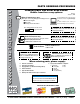
www.multiquip.com Parts Ordering Procedures ordering parts has never been easier! Choose from three easy options: order via internet (Dealers only): best Deal! Effective: January 1st, 2006 If you have an MQ Account, to obtain a Username and Password, E-mail us at: parts@multiquip. com. Order parts on-line using Multiquip’s SmartEquip website! ■ View Parts Diagrams ■ Order Parts ■ Print Specification Information To obtain an MQ Account, contact your District Sales Manager for more information.
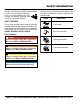
Safety Information Do not operate or service the equipment before reading the entire manual. Safety precautions should be followed at all times when operating this equipment. Failure to read and understand the safety messages and operating instructions could result in injury to yourself and others. Potential hazards associated with the operation of this equipment will be referenced with hazard symbols which may appear throughout this manual in conjunction with safety messages.
Safety Information general saFetY Caution never operate this equipment without proper protective clothing, shatterproof glasses, respiratory protection, hearing protection, steel-toed boots and other protective devices required by the job or city and state regulations. Avoid wearing jewelry or loose fitting clothes that may snag on the controls or moving parts as this can cause serious injury. never operate this equipment when not feeling well due to fatigue, illness or when under medication.
Safety Information pump saFetY Danger never operate the equipment in an explosive atmosphere or near combustible materials. An explosion or fire could result causing severe bodily harm or even death. Warning Accidental starting can cause severe injury or death. alWaYs place the ON/OFF switch in the OFF position. Do not place hands or fingers inside pump when pump is running. never disconnect any emergency or safety devices. These devices are intended for operator safety.
Safety Information NOTICE alWaYs make certain that the voltage supplied to the pump is correct. Always read the pump’s nameplate to determine what the power requirements are. power Cord/Cable safety Dan never stand in water while AC power cord is connected to a live power source. never use damaged or worn cables or cords. Inspect for cuts in the insulation. Control box safety Danger alWaYs have a qualified electrician perform the control box installation.
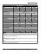
specifications Table 1. Specifications ST41230 ST41460 ST61230 Centrifugal Centrifugal Centrifugal Chrome Steel Chrome Steel Chrome Steel 4.00 (101) 4.00 (101) 6.00 (152) 0.60 in (15.2) Model ST61460 Type Centrifugal Impeller Chrome Steel Discharge Size in. (mm) 6.00 (152) Max Solids in. (mm) Maximum Pumping Capacity 423 (1,600) 423 (1,600) 674 (2,450) 674 (2,450) gallons/min (liters/min.) Max Head ft. (m) 138 ft. (42.1) 138 ft. (42.1) 105 ft. (32.5) 105 ft. (32.5) Power HP (kW) 10 (7.5) 10 (7.
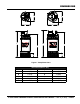
dimensions B G F A C H J E D I Figure 1. Pump Dimensions REF. DES. A B C D E Table 2. Dimensions in. (mm) ST41230/ST4160 REF. DES. F 11 (279) G 11 (279) H 32.5 (826) I 5.5 (140) J 28.25 (718) ST61230/ST6160 14 (356) 14 (356) 34.75 (883) 5.5 (140) 31.0 (787) st4/ST6 series submersible pumps• operation AND PARTS manual — rev.
general information The Multiquip Model ST41230/ST41460 and ST61230/ ST61460 submersible pumps are designed to pump water. These pumps work best when faced with high head applications where you need an appreciable flow. The pumping of flammable, toxic, corrosive, abrasive liquids is strictly forbidden. These pumps are best suited for clear water applications where maximum size of solids (debris) does not exceed 0.6-inches (15.2 mm).
components 7 6 5 11 7 8 8 12 4 4 ST41230 ST41460 3 3 2 1 9 10 2 ST61230 ST61460 9 10 1 Figure 2. Submersible Pump Components Figure 2 shows the location of the basic components, for the submersible pumps. Listed below is a brief explanation of each component. 1. Strainer Base – This strainer base is made of stainless steel which is resistant to hardware corrosion. For dewatering purposes, always place the strainer base on a platform. 2.
float switches Mechanical Float Switch Design Features Mechanically activated float switches offer a reliable low current control for dewatering applications. Float switch housings are constructed of high-impact, corrosion resistant polypropylene with mechanically activated, snap action contacts. How It Works The mechanical float switch control will turn ON (close) when the float tips 45° above -horizontal, indicating a high level, and turns OFF (opens) when the float switch drops 45° below horizontal.
float switches Float Switches Mounting The Float Switches For unattended operation of the submersible pump two single float switches (Model SW-1WOPA) will be required. These float switches can be connected directly to a control box (bare wires) and will allow the pump to turn on and off depending on the length of the tether. 1. Determine the required cord tether length as shown in Figure 3 and Table 3. 2. Place the cord into the clamp as shown in Figure 6. 3.
float switches Control Boxes For remote pumping applications, all four model submersible pumps will require a control box (Figure 7). CAUTION! HIGH VOLTAGE! For each model submersible pump there is an associated control box. Reference Table 4 for the desired control box and applicable heater. The heater size is determined by the the full load amps the pump will draw.
control box installation Control Box Installation CONTROL BOX MOUNTING The following procedure outlines the steps for connecting the pump to a control box. Mount the control box in an upright vertical position. Make sure the control box is securely fastened to a flat surface, that is free of dust, dirt, moisture or any elements that may contaminate or erode the electronic components of the control box. DANGER Each submersible pump is designed to work with a control box.
control box installation Connecting SW-1WOPA Float Switches to Control Box 1. Remove the float switch input connector housing, then route the float switch wires through the cable gland on the control box. Attach the wires of the float switch to the terminal block as indicated by Table 6 and Figure 8. Table 6. Dual Float switch Connections Wire Float Terminal Block No. Color Switch TB1-A1 Black Start TB1-A2 White TB1-A3 Black Stop TB1-A4 White 2.
control Box power connections 3-Phase Power Installation (Input to Control Box) 3-Phase Power Installation (Output To Pump) 1. The 3-phase input power cord should have four wires. Each wire is color coded. The colors are RED, WHITE, BLACK and GREEN. 1. The 3-phase output power cord should have four wires. Each wire is color coded. The colors are RED, WHITE, BLACK and GREEN. 2.
control box wiring layout MOUNT CONTROL BOX IN AN UP-LEFT VERTICAL POSITION AS SHOWN. C FN M-8/10 XF 3 4 DUEL-ELE FUSE FUSET X1 230 220 240 H1 1 2 TRANSFORMER H2 X2 110 115 120 H3 H4 XF 460 440 480 X1 12 3 4 3- 50/60HZ 105 2- OFF/ON LAMP 4- 4T2 2T1 2T1 H1 75VA TEMP. CL. 1- U.S. PAT. NO. 3516040 -4 AC POWER TERMINAL BLOCK ImperviTRAN (R ) B075BTZ13JK -3 H3 4- CONTROLLER CAT. NO.
operation Pump Placement LOWER LOWER 1. Attach a suitable lifting chain to the eye bolts or lift handle (Figure 9) on the pump. Use a crane, or similar lifting device and lower the pump into place. For applications where there is an excessive amount of mud, grit or silt, the use of a support platform is desirable. 2. Make sure the pump is always placed in an upright position, not tilted (Figure 10). Never position the pump directly on a soft, loose bottom.
operation Control Box Operation (Manual Mode) Reset Button 1. From the voltage source, set the circuit breaker or quick disconnect switch to the ON position. 1. When the electronic overload module detects an overload condition, the pump will shut down. Check the pump and correct the cause of ther overload. 2. For manual operation of the pump, place the 3-position operation switch (Figure 11) on the control box in the MANUAL position. 2.
maintenance Lubrication Inspecting Lubrication Oil (Mechanical Seal) To check the lubrication oil level of the mechanical seal perform the following: 1. Block the oil fill opening with a finger and roll pump to one side to drain (Figure 17) oil into a small transparent container. Checking Lubrication Oil Level 1. Lay the pump (Figure 16) on its side with the oil plug facing upwards. 2. If oil is cloudy (milky) or has water in it, indicates that mechanical seal is defective or worn.
maintenance Impeller Removal Refer to the the following procedure and Figure 18 for the removal of the impeller. ST61230/ST61460 ST41230/ST41460 1. Remove oil screw and gasket from the oil fill chamber port. Drain oil from oil chamber as referenced in Figure 18. 2. Remove the four hex nuts and lock washers that secure the base plate to the inlet plate. 3. Remove base plate, inlet plate, o-ring and strainer. 4. Next, remove the four bolts and lock washers that secure pump casing to the seal bracket. 5.
maintenance Water Tank Storage NOTICE If an installed pump (immersed in water) has not been in operation for a long period of time, check the insulation resistance and run the pump for 30 minutes every month. Insulation resistance is moisture and temperature sensitive. When temperature increases, insulation resistance decreases, and vice versa.
notes page 24 — st4/ST6 series submersible pumps • operation AND PARTS manual — rev.
troubleshooting Table 9. Pump Troubleshooting SYMPTOM Pump Fails To Start Pump Fails to Deliver Full Output Water in Mechanical Seal Oil POSSIBLE PROBLEM SOLUTION Incorrect voltage/amps? Check that the proper voltage, 230 or 460 VAC, 60 Hz, 3-phase is being supplied to the pump. Also check that there is an adequate amount of current (amps) to run the pump. Check power source circuit breaker. Check electrical connections? If using float switches check wiring, inspect power cord.
control box wiring diagram (CB1269/CB1274) EXTERNAL 3-PHASE (230 VAC) POWER SOURCE CIRCUIT BREAKER L2 L2 L3 L3 GREEN L2 L3 M L1 L1 RED WHITE BLACK L1 230 VAC THREE PHASE WIRING CONNECTIONS CB1269 CB1274 POWER INPUT H1 O/L RED AWG 8 RED RED AWG 8 WHT RED AWG 8 BLK H3 H2 WHT XF FUSE 1/2 AMP X2 X1 GRN 2 MAN 4 AUTO BLK 1 OVERLOAD RELAY OFF O/L X2 NC ON INDICATOR LAMP L1 L2 RED AWG 10 RED AWG 10 FUSE 4 X2 X1 XF H3 A1 TERMINAL BLOCK H1 110 115 120 X1 4 JUMPER TABS
control box wiring diagram (CB1456/CB1463) CB1456 CB1463 POWER INPUT EXTERNAL 3-PHASE (460 VAC) POWER SOURCE CIRCUIT BREAKER L2 L2 L3 O/L RED AWG 8 RED RED AWG 8 WHT RED AWG 8 L3 L3 GREEN L2 M L1 L1 RED WHITE BLACK L1 460 VAC THREE PHASE WIRING CONNECTIONS H1 H3 SEE TABLE 4 FOR CORRECT HEATER SELECTION CONTROL TRANSFORMER 50VA CPT WHT XF FUSE 1/2 AMP X2 X1 GRN OVERLOAD RELAY MAN 2 BLK 1 OFF O/L X2 NC AUTO 4 ON INDICATOR LAMP L1 L2 RED AWG 10 RED AWG 10 FUSE 4 X2 X1 X
EXPLANATION OF CODES IN REMARKS COLUMN The following section explains the different symbols and remarks used in the Parts section of this manual. Use the help numbers found on the back page of the manual if there are any questions. NOTICE The contents and part numbers listed in the parts section are subject to change without notice. Multiquip does not guarantee the availability of the parts listed. SAMPLE PARTS LIST no. 1 2% 2% 3 4 part no. part name QtY. REMARKS 12345 BOLT .....................1 .....
SUGGESTED SPARE PARTS ST41230/ST41460 AND ST61230/ST61460 SUBMERSIBLE PUMPS 1 to 3 units Qty. P/N Description 1............432230-01.............MECHANICAL SEAL 1............4214335-01...........OIL SEAL 1............86414475n............O-RING GASKET SET (ST41230/ST41460) 1............86414110...............O-RING GASKET SET (ST61230/ST61460) NOTICE Part numbers on this Suggested Spare Parts list may supersede/replace the part numbers shown in the following parts lists.
ST41230/ST41460 ASSY. 73G 73 73A 75 2 75A 75C 19 73 81 41D 1 68 45 66 73B 75B 73F 18 75E 65A 4A 43 73C 41D 41A 73D 75C 45B 45A 45B 67 4 73J 81A 73D 11 15 41 75I 73E 3 79 75H 71 75D 42 75F 75G 74 41C 10 32 82 O-RING AND GASKETS SET 75 76 77 31 73H 41B 12 75 17 73L 13 65 9 41 76A 79A 75 74A page 30 — st4/ST6 series submersible pumps • operation AND PARTS manual — rev.
ST41230/ST41460 ASSY. NO. 1 2 3 4 4A 9 10 11 12 13 15 17 18 19 31 31 32 41$ 41A$ 41B$ 41C$ 41D$ 42 43 45$ 45A$ 45B$ 65 65A 66 67 68 71 71 73 73A 73B 73C 73D 73E 73F 73G 73H 73L 73J 74 74A PART NO.
ST41230/ST41460 ASSY. 73G 73 73A 75 2 75A 75C 19 73 81 41D 1 68 45 66 73B 75B 73F 18 75E 65A 4A 43 73C 41D 41A 73D 75C 45B 45A 45B 67 4 73J 81A 73D 11 15 41 75I 73E 3 79 75H 71 75D 42 75F 75G 74 41C 10 32 82 O-RING AND GASKETS SET 75 76 77 31 73H 41B 12 75 17 73L 13 65 9 41 76A 79A 75 74A page 32 — st4/ST6 series submersible pumps • operation AND PARTS manual — rev.
ST41230/ST41460 ASSY. NO. 75 75A 75B 75C 75D 75E 75F 75G 75H 75I 76 76A 76A 77 79 79A 81 81A 81A 82 PART NO. 753430010-01 753430006-01 753430012-01 753430008-01 751306304 753430005-01 752430025-01 752430016-03 753430016-01 757300004 7630STW40 7630RTW90 7630RTW40 771433-01 79363041 79363081 8102554150131 81G1001 811202 86414475N PART NAME QTY.
ST61230/ST61460 ASSY. 41B 73A 81 75 68A 75A 73B 73 1 73D 75B 45 68 73C 66 41 75B 73F 18 75E 45 76B 43 4A 73G 73D 45A 11 45C 45B 75B 75I 71 75C 81A 75D 15 73E 75G 3 41D 41F 10 75F 74 75B 79 73H 41B 32 76 82 O-RING AND GASKETS SET 73G 67 77 4 73J 45C 42 12 74A 75B 31 73I 73D 17 75B 74A 76A 79A 41A 19 13 73D 75B 9 75H 74A 75B page 34 — st4/ST6 series submersible pumps • operation AND PARTS manual — rev.
ST61230/ST61460 ASSY. NO. 1 3 4 4A 9 10 11 12 13 15 17 18 19 31 31 32 41$ 41A$ 41B$ 41D$ 41F$ 42 43 45$ 45A$ 45B$ 45C$ 66 67 68 68A 71 71 73 73A 73A 73B 73C 73D 73E 73F 73G 73H 73I 73J 74 74A PART NO.
ST61230/ST61460 ASSY. 41B 73A 81 75 68A 75A 73B 73 1 73D 75B 45 68 73C 66 41 75B 73F 18 75E 45 76B 43 4A 73G 73D 45A 11 45C 45B 75B 75I 71 75C 81A 75D 15 73E 75G 3 41D 41F 10 75F 74 75B 79 73H 41B 32 76 82 O-RING AND GASKETS SET 73G 67 77 4 73J 45C 42 12 74A 75B 31 73I 73D 17 75B 74A 76A 79A 41A 19 13 73D 75B 9 75H 74A 75B page 36 — st4/ST6 series submersible pumps • operation AND PARTS manual — rev.
ST61230/ST61460 ASSY. NO. 75 75A 75B 75C 75D 75E 75F 75G 75H 75I 76 76A 76B 77 79 79A 81 81 81A 81A 82 PART NO. 753430008-01 753430006-01 753430010-01 757300004 751306306 753430005-01 752430016-03 753430016-01 752430010-01 752430025-01 7630STW40 7630RTW90 7607-01 771433-01 79363061 79363081 8102804150171 8102554150171 81G0801 811202 86414110 PART NAME QTY.
Terms and Conditions of Sale — Parts paYment terms 5. Parts must be in new and resalable condition, in the original Multiquip package (if any), and with Multiquip part numbers clearly marked. 6. The following items are not returnable: Multiquip reserves the right to quote and sell direct to Government agencies, and to Original Equipment Manufacturer accounts who use our products as integral parts of their own products. a. speCial eXpeDiting serviCe Terms of payment for parts are net 30 days.
notes st4/ST6 series submersible pumps• operation AND PARTS manual — rev.
Operation and Parts Manual HERE’S HOW TO GET HELP PLEASE HAVE THE MODEL AND SERIAL NUMBER ON-HAND WHEN CALLING UNITED STATES Multiquip Corporate Office 18910 Wilmington Ave. Carson, CA 90746 Contact: mq@multiquip.com MQ Parts Department Tel.