Operation and Parts Manual HTH-SERIES RIDE-ON POWER TROWEL Revision #6 (02/22/11) To find the latest revision of this publication, visit our website at: www.multiquip.com THIS MANUAL MUST ACCOMPANY THE EQUIPMENT AT ALL TIMES.
PROPOSITION 65 WARNING Engine exhaust and some of its constituents, and some dust created by power sanding, sawing, grinding, drillingandotherconstructionactivities contains chemicals known to the State of California to cause cancer, birth defects and other reproductive harm. Some examples of these chemicals are: Leadfromlead-basedpaints. Crystalline silicafrombricks. Cementandothermasonryproducts. Arsenicandchromiumfromchemically treatedlumber.
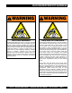
SILICOSIS/RESPIRATORY WARNINGS WARNING WARNING SILICOSIS WARNING RESPIRATORY HAZARDS Grinding/cutting/drilling of masonry, concrete, metal and other materials with silica in their composition may give off dust or mists containing crystalline silica. Silica is a basic component of sand, quartz, brick clay, granite and numerous other minerals and rocks. Repeated and/or substantial inhalation of airborne crystalline silica can cause serious or fatal respiratory diseases, including silicosis.
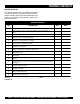
TABLE OF CONTENTS Proposition 65 Warning........................................... 2 Silicosis/Respiratory Warnings................................ 3 Table of Contents..................................................... 4 Parts Ordering Procedures...................................... 5 Training Checklist ................................................... 6 Daily Pre-Operation Checklist................................. 7 Safety Information..............................................8-13 Specifications.
www.multiquip.com PARTS ORDERING PROCEDURES Ordering parts has never been easier! Choose from three easy options: Order via Internet (Dealers Only): Best Deal! Effective: January 1st, 2006 If you have an MQ Account, to obtain a Username and Password, E-mail us at: parts@multiquip. com. Order parts on-line using Multiquip’s SmartEquip website! ■ View Parts Diagrams ■ Order Parts ■ Print Specification Information To obtain an MQ Account, contact your District Sales Manager for more information.
TRAINING CHECKLIST TRAINING CHECKLIST This checklist will lists some of the minimum requirements for machine maintenance and operation. Please feel free to detach it and make copies. Use this checklist whenever a new operator is to be trained or it can be used as a review for more experienced operator’s. TRAINING CHECKLIST NO. DESCRIPTION 1 Read Operator’s Manual completely. 2 Machine layout, location of components, checking of engine and hydraulic oil levels.
DAILY PRE-OPERATION CHECKLIST DAILY PRE-OPERATION CHECKLIST DAILY PRE-OPERATION CHECKLIST 1 Engine oil level. 2 Hydraulic oil level. 3 Radiator coolant level. 4 Condition of blades. 5 Blade pitch operation. 6 Kill switch (seat) operation. 7 Steering control operation. COMMENTS: HTH-8 FT. RIDE-ON POWER TROWEL — OPERATION AND PARTS MANUAL — REV.
SAFETY INFORMATION Do not operate or service the equipment before reading the entire manual. Safety precautions should be followed at all times when operating this equipment. Failure to read and understand the safety messages and operating instructions could result in injury to yourself and others. Potential hazards associated with the operation of this equipment will be referenced with hazard symbols which may appear throughout this manual in conjunction with safety messages.
SAFETY INFORMATION GENERAL SAFETY CAUTION NEVER operate this equipment without proper protective clothing, shatterproof glasses, respiratory protection, hearing protection, steel-toed boots and other protective devices required by the job or city and state regulations. Avoid wearing jewelry or loose fitting clothes that may snag on the controls or moving parts as this can cause serious injury. NEVER operate this equipment when not feeling well due to fatigue, illness or when under medication.
SAFETY INFORMATION TROWEL SAFETY NOTICE ALWAYS keep the machine in proper running condition. DANGER Engine fuel exhaust gases contain poisonous carbon monoxide. This gas is colorless and odorless, and can cause death if inhaled. The engine of this equipment requires an adequate free flow of cooling air. NEVER operate this equipment in any enclosed or narrow area where free flow of the air is restricted.
SAFETY INFORMATION NOTICE NEVER run engine without an air filter or with a dirty air filter. Severe engine damage may occur. Service air filter frequently to prevent engine malfunction. NEVER tamper with the factory settings of the engine or engine governor. Damage to the engine or equipment can result if operating in speed ranges above the maximum allowable. FUEL SAFETY DANGER BATTERY SAFETY DANGER DO NOT drop the battery. There is a possibility that the battery will explode.
SAFETY INFORMATION TRANSpORTING SAFETY CAUTION NEVER allow any person or animal to stand underneath the equipment while lifting. Ride-on trowels are very heavy and awkward to move around. Use proper heavy lifting procedures and DO NOT attempt to lift the trowel by the guard rings. NOTICE The easiest way to lift the trowel is to utilize the lift loops that are welded to the frame. These lift loops are located to the left and right sides of the operator’s seat.
SAFETY INFORMATION Trailer should be adjusted to a level position at all times when towing. Raise and lock trailer wheel stand in up position when towing. Place chock blocks underneath wheel to prevent rolling while parked. Place support blocks underneath the trailer’s bumper to prevent tipping while parked. Use the trailer’s swivel jack to adjust the trailer height to a level position while parked. ENVIRONMENTAL SAFETY NOTICE Dispose of hazardous waste properly.
HTH — SPECIFICATIONS ON EHEAT PR HAUFFAG EC E PR OFF HYDROSTATIC DRIVE C HEIGHT 1 B WIDTH A LENGTH Figure 1. HTH Dimension /Specifications Table 2. HTH Specifications SPECIFICATION PARAMETER HTH-38KD (KUBOTA) HTH-31V (VANGUARD) A–Length – in. (cm) 96.75 (245.8) 96.75 (245.8) B–Width – in. (cm) 50.0 (127) 50.0 (127) C–Height – in. (cm)1 55.0 (140) 55.0 (140) Weight – lbs. (kgs.) Operating 1,306 (592) 1,200 (544) Weight – lbs. (kgs.
HTH — GENERAL INFORMATION HTH RIDE-ON TROWEL FAMILIARIZATION Hydraulic Steering The HTH series Ride-On Power Trowels are designed for the floating and finishing of concrete slabs. Dual joystick controls located to the left and right of the operator are provided for steering the HTH-Ride on Power Trowel. The joysticks are linked to three hydraulic steering cylinders located within the frame of the machine.
HTH — CONTROLS AND INDICATORS Figures 2 and 3 show the location of the controls, indicators and general maintenance parts. Each control may perform more than one function. All functions of each control are described below. 1. Seat – Place for operator to sit. Engine will not start unless operator is seated. Seat is adjustable. 2. Steering Control (right side) -Allows the unit to move in either a forward, reverse left or right direction. 3. Throttle Control Lever – Controls the speed of the engine.
HTH — CONTROLS AND INDICATORS 27. Oil Filter – Provides oil filtering for the engine. 28. Retardant Spray Motor – Used with the spray control button. 29. Retardant Spray Tank - Holds 5 gallons of retardant or water. 30. Battery - Provides +12V DC power to the electrical system. 31. Hydraulic Suction Filter - Filters hydraulic fluid prior to entering the system. 32. Hydraulic Return Filter - Filters hydraulic returning to reservoir.
HTH — INITIAL START-UP This section is intended to assist the operator with the initial start-up of the HTH series Ride-On Power Trowel. It is extremely important that this section be read carefully before attempting to use the trowel in the field. Fuel 1. DO NOT use your ride-on power trowel until this section is thoroughly understood. CAUTION Failure to understand the operation of the HTH Ride-On Power Trowel could result in severe damage to the trowel or personal injury.
HTH — INITIAL START-UP 3. 4. It is recommended that the kill switch be used to stop the engine after every use. Doing this will verify that the switch is working properly and presents no danger to the operator. Remember to turn the key to the “OFF” position after stopping the machine. Not doing so may drain your units’ battery. Place the engine throttle lever (Figure 7) in the LOW position.
HTH — INITIAL START-UP Table 3. Joystick Directional Positioning DIRECTION RESULTS Causes only the left side Left Move Joystick Forward of the ride-on trowel to move forward. Causes only the left side Left Move Joystick Backward of the ride-on trowel to move backward. Causes only the right side Right Move Joystick Forward of the ride-on trowel to move forward. Causes only the right side Right Move Joystick Backward of the ride-on trowel to move backward.
HTH — MAINTENANCE NOTE See the engine manual supplied with your machine for appropriate engine maintenance schedule and troubleshooting guide for problems. At the front of the book (Page B) there is a “Daily Pre-Operation Checklist”. Make copies of this checklist and use it on a daily basis. CAUTION! Blade speed adjustment is a two-step process. First, the left spider’s speed should be checked and/or adjusted. Second, the right spider’s speed should be adjusted to match the left.
HTH — MAINTENANCE PUMP ACTUATION LEVERS ADJUSTMENT NUT There are some things to look for when checking to see if adjustment is necessary. Is the machine wearing out blades unevenly (i.e.
HTH — MAINTENANCE Changing A Blade Whiteman recommends that all the blades on the entire machine be changed at the same time. If only one or some of the blades are changed at one time, the machine will not finish concrete consistently and the machine may wobble or bounce. 1. Place the machine on a flat, level surface. Adjust the blade pitch control to make the blades as flat as possible. Note the blade orientation on the trowel arm.
HTH — TROUBLESHOOTING Troubleshooting (Ride-On Mechanical Trowel) Symptom Engine running rough or not at all. Safety stop switch not functioning. Possible Problem Stop switch malfunction? Make sure that the stop switch is functioning when the operator is seated. Replace switch if necessary. Fuel? Look at the fuel system. Make sure there is fuel being supplied to the engine. Check to ensure that the fuel filter is not clogged.
HTH — TROUBLESHOOTING Troubleshooting (Ride-On Mechanical Trowel) - continued Symptom Lights (optional) not working. Retardant spray (optional) not working. Steering is unresponsive. Operating position is uncomfortable. Power head on Electric Pitch (optional) not working. Linkage on Twin Pitch not working. Possible Problem Solution Wiring? Check all electrical connections in the lighting circuit. Verify wiring is in good condition with no shorts. Replace defective wiring or components immediately.
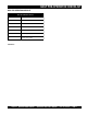
EXPLANATION OF CODE IN REMARKS COLUMN The following section explains the different symbols and remarks used in the Parts section of this manual. Use the help numbers found on the back page of the manual if there are any questions. NOTICE The contents and part numbers listed in the parts section are subject to change without notice. Multiquip does not guarantee the availability of the parts listed. Sample partS liSt NO. 1 2% 2% 3 4 part NO. part Name QtY. remarKS 12345 BOLT......................1 .....
HTH — SUGGESTED SPARE PARTS 1 to 3 Units Qty. P/N Description 4............. 0183........................COTTER PIN 6............. 10221......................BUSHING 2............. 11648......................YOKE PIVOT SHAFT 1............. 10208......................MUFFLER (VANGUARD) 1............. 11732......................MUFFLER (KUBOTA) 1............. 12194......................HEAT SHIELD (VANGUARD) 1............. 11993......................OVERFLOW BOTTLE 6............. 11984......................
HTH — LEFT/RIGHT PIVOT ASSY 7 1 RIGHT SIDE PIVOT ASSEMBLY (VIEW FROM OPERATORS SEAT) 6 4 20 21 13 6 6 17 1 18 9 10 8 25 2 1 2 24 7 16 3 4 23 5 2 11 3 19 15 NOTES: 5 22 1 TORQUE TO 50 FT. LBS 2 2 TORQUE TO 60 FT. LBS 3 APPLY LOCTITE. 3 6 27 4 SEE PAGE 44 FOR HYDRAULIC MOTOR HOSE CONNECTIONS. 5 PLACE FLUSH HEAD SCREW IN BACK OF MOUNT AS SHOWN. 6 PLACE HEX HEAD SCREW IN FRONT OF MOUNT AS SHOWN. PAGE 28 — HTH-8 FT. RIDE-ON POWER TROWEL — OPERATION AND PARTS MANUAL — REV.
HTH — LEFT/RIGHT PIVOT ASSY HTH-8 FT. RIDE-ON POWER TROWEL — OPERATION AND PARTS MANUAL — REV.
HTH — LEFT/RIGHT PIVOT ASSY NO 1 2 3 4 5 6 7 8 9 10 11 12 13 14 15 16 17 18 19 20 21 22 23 24 25 26 27 PART NO 0166 A 0183 0448 10138 10176 10221 1023 11154 11420 11425 11434 11445 11450 11474 11499 11548 11555 11578 11648 11772 11773 11882 12051 12065 12066 13178 2549 PART NAME WASHER, LOCK, 3/8 MED PIN, COTTER 1/8 X 1 1/4 WASHER, FLAT, 7/16 SAE SCREW, SHS 1/4-20 X 1/2, N.P. NUT, NYLOC 1/2-13 BUSHING, 1 ID x 1.
HTH — NOTE PAGE HTH-8 FT. RIDE-ON POWER TROWEL — OPERATION AND PARTS MANUAL — REV.
HTH — LEFT/RIGHT TWIN PITCH ASSY LEFT SIDE TWIN PITCH TOWER ASSEMBLY P/N 11651 ITEM 55 (VIEW FROM OPERATOR'S SEAT). 25 1 57 3 60 58 2 59 62 6 62 23 29 63 65 67 2 38 64 66 10 4 15 9 34 29 27 37 24 40 28 30 34 33 22 5 20 36 11 7 69 2 12 1 35 14 20 8 16 19 B 68 2 26 2 NOTES: LEVER ASSEMBLY, ITEM 57 1 INCLUDES ITEMS WITHIN OUTLINE. 13 A CONTINUED ON NEXT PAGE SEE A , ITEM 32. CONTINUED ON NEXT PAGE SEE B , ITEM 31.
HTH — LEFT/RIGHT TWIN PITCH ASSY CONTINUED FROM A , ITEM 13 CONTINUED FROM PART OF LEFT SIDE TWIN PITCH TOWER ASSEMBLY B , ITEM 19 31 32 B A 24 49 18 1 56 24 49 2 20 14 39 17 20 21 48 24 45 41 43 3 42 53 47 29 24 44 50 43 52 3 51 3 45 NOTES: MITER BOX ASSEMBLY, ITEM 56 1 INCLUDES ITEMS WITHIN OUTLINE. 2 ITEM 49 (VERTICAL SHAFT) COUPLES THE LEFT AND RIGHT SIDES OF THE TWIN PITCH CONTROLS. BOTH LEFT AND RIGHT SIDES ARE IDENTICAL UNLESS OTHERWISE NOTED.
HTH — LEFT/RIGHT TWIN PITCH ASSY LEFT/RIGHT TWIN PITCH ASSY NO 1+% 2+% 3 +% 4+% 5+% 6+% 7+% 8+ 9+% 10+% 11+ 12+% 13+% 14 +% 15 +% 16+% 17 18 19+% 20 +% 21 22+% 23+% 24 +% 25+% 26+% 27+% 28+% 29 +% 30+% 31 32 33+% 34+% 35+% 36+% 37+% 38 +% 39 40+% 41 42 43 44 45 46 47 48 49 50 * * * * * * * * * * * * * * * PART NO 0126 B 0161C 0181 B 0655 0685 0948 10382 10511 10512 10546 10722 10723 1116 11583 1162 A 11623 11630 11649 11652 11654 1499 1529 1530 1578 1579 1586 1604 1612 1733 2007 2012 2156 2169 2170 2311
HTH — LEFT/RIGHT TWIN PITCH ASSY LEFT/RIGHT TWIN PITCH ASSY NO * * 51 52 53 54 55 56 57 58# 59# 60# 61# 62# 63# 64# 65# 66# 67# 68% 69% * PART NO 2845 4514 5283 11650 11651 11655 1617 2300 2332 4014 4403 3231 1615 1733 1616 0185 1528 10510 10721 PART NAME SHAFT, MITER BOX HORIZ SCREW, HHC 1/4 – 20 X 5/8 NUT, NYLOC 5/16 – 18 RIGHT SIDE TWIN PITCH CONT ASSY LEFT SIDE TWIN PITCH TOWER ASSY MITER BOX ASSY LEVER ASSY, TROWEL ADJUSTMENT DECAL, AL PITCH, RH DECAL, AL PITCH, LH SCREW, 2-3/16 P-K TYPE U DRIVE
HTH — ENGINE (VANGUARD) PAGE 36 — HTH-8 FT. RIDE-ON POWER TROWEL — OPERATION AND PARTS MANUAL — REV.
HTH — ENGINE (VANGUARD) HTH-8 FT. RIDE-ON POWER TROWEL — OPERATION AND PARTS MANUAL — REV.
HTH — ENGINE (VANGUARD) ENGINE ( VANGUARD) NO 1 2 3 4 5 6 7 8 9 10 11 12 13 14 15 16 17 18 19 20 21 22 23 24 25 26 27 28 29 30 31 32 33 34 35 36 37 38 39 40 41 42 43 44 45 46 47 48 49 50 51 PART NO 0131 A 0161 C 0166 A 0300 B 0730 0948 10024 10136 10176 10208 10370 10434 10463 11292 11323 11353 11363 11377 11517 11577 11756 11757 11804 11819 11821 11822 11827 11833 11834 11899 11900 12103 12194 13211 19468 19473 2866 2955 3242 3333 5054 A 5218 60013 60025 6869 8126 4514 0181 B 11993 12497 11984 PART NAM
HTH — NOTE PAGE HTH-8 FT. RIDE-ON POWER TROWEL — OPERATION AND PARTS MANUAL — REV.
HTH — ENGINE (KUBOTA) PAGE 40 — HTH-8 FT. RIDE-ON POWER TROWEL — OPERATION AND PARTS MANUAL — REV.
HTH — ENGINE (KUBOTA) HTH-8 FT. RIDE-ON POWER TROWEL — OPERATION AND PARTS MANUAL — REV.
HTH — ENGINE (KUBOTA) ENGINE (KUBOTA) NO 1 2 3 4 5 6 7 8 9 10 11 12 13 14 15 16 17 18 19 20 21 22 PART NO 0105 0166 A 0300 B 10136 11517 11520 11577 11597 11618 11662 11732 11740 19473 2955 5054 A 5218 5283 60004 60028 6869 8125 11984 PART NAME SCREW, HHC 5/16-18 X 1 1/2 WASHER, LOCK, 3/8 MED WASHER, FLAT, 5/16 SAE WASHER, FLAT, 3/8 SAE MOUNT, RIGHT MOTOR W/A MOUNT, LEFT MOTOR W/A MOUNT, MACHINERY ENGINE, KUBOTA 33HP, V1505 BRACKET, THROTTLE W/A SCREW, HHC M10 – 125 X 25 MM MUFFLER W/A, 38 KUB (ASSY ON
HTH — NOTE PAGE HTH-8 FT. RIDE-ON POWER TROWEL — OPERATION AND PARTS MANUAL — REV.
HTH — ENGINE (KUBOTA) BELOW S/N JG53027 13 18 19 28" 14" 13 TRANSFER PUMP 13 CANNISTER FUEL FILTER 19 17" 4" 13 19 32 16 24 23 IN-LINE FUEL FILTER 31 22 16 2 25 19 21" 16 27 26 NOTES: 25 NK E TA LIN EL N FU UR NK NE RET A I T EL Y L FU PPL SU 1 MOUNT FUEL TANK UNDERNEATH PLATFORM ASSEMBLY. USE ITEMS 29, 30 AND 31 TO SECURE FUEL TANK MAIN FRAME ASSEMBLY. 1 2 FUEL CONNECTIONS REPRESENT EARLIER HTH KUBOTA MODELS 30 29 28 PAGE 44 — HTH-8 FT.
HTH — ENGINE (KUBOTA) BELOW S/N JG53027 ENGINE (KUBOTA) BELOW S/N JG53027 NO 1 2 3 4 5 6 7 8 9 10 11 12 13 14 15 16 17 18 19 20 21 22 23 24 25 26 27 28 29 30 31 32 PART NO 0105 0166 A 0300 B 10136 11517 11520 11577 11597 11618 11662 11732 11740 19473 2955 5054 A 5218 5283 60004 60028 6869 8125 11984 12002 12019 19601 19594 11675 0131A 0181B 0948 11978 2914 PART NAME SCREW, HHC 5/16-18 X 1 1/2 WASHER, LOCK, 3/8 MED WASHER, FLAT, 5/16 SAE WASHER, FLAT, 3/8 SAE MOUNT, RIGHT MOTOR W/A MOUNT, LEFT MOTOR W/A
HTH — HYDRAULIC STEERING ASSY PAGE 46 — HTH-8 FT. RIDE-ON POWER TROWEL — OPERATION AND PARTS MANUAL — REV.
HTH — HYDRAULIC STEERING ASSY HYDRAULIC STEERING ASSY NO 1 2 3 4 5 6 7 8 9 10 11 12 13 14 15 16 17 18 19 20 21 22 23 24 25 26 27 28 29 30 31 32 PART NO 0161 C 0300 B 0447 10176 10229 11141 11142 11146 11422 11423 11455 11614 11619 11676 11686 11696 11698 11699 11721 11722 11723 11724 11725 11780 11910 11956 12038 12056 12060 2549 4692 5283 PART NAME WASHER, LOCK, 5/16 MED WASHER, FLAT, 5/16 SAE WASHER, FLAT, 1/2 SAE NUT, NYLOC 1/2-13 SCREW, HHC 5/16-24 X 1 SPACER, ROD END ROD END, 1/2-20 MALE RH NUT, H
HTH — VALVE ASSY (LEFT SIDE) 1 8 13 1 2 12 21 7 19 20 4 11 7 22 10 6 5 18 4 9 6 6 3 7 3 2 14 8 2 15 NOTES: PORT "A" PORT "B" 1 TORQUE TO 48 + 5 FT. LBS 2 TORQUE TO 33 + 3.5 FT. LBS 3 TORQUE TO 14 + 1.5 FT. LBS 4 TORQUE TO 7 + 1.0 FT. LBS 5 TORQUE TO 18 + 2.0 FT. LBS 17 5 16 6 FOR COMPLETE VALVE ASSY. USE PART NUMBER 11423. 7 LUBRICATE PIVOT JOINT, PLATE AND PLUNGER CONTACT AREAS AS REQUIRED. 8 FOR LEFT HANDLE PARTS BREAKDOWN SEE PAGE 46. PAGE 48 — HTH-8 FT.
HTH — VALVE ASSY (LEFT SIDE) VALVE ASSY (LEFT SIDE) NO PART NO PART NAME QTY. REMARKS * 11423 VALVE ASSY 1............................ INCLS. ITEMS W/ 1 11619 HANDLE, LEFT VALVE 1 2 12519 BOOT, RIGHT 1 3 HU51761 CAP SCREW-FLAT HD 1 4 HU53616 RETAINING RING-EXT 2 5 12536 GASKET 2 6 HU53748 SPRING 2 7 12522 PLUNGER CAPSULE ASSY. 2 8 12521 METERING CAPSULE ASSY. 2 9 HU7472-A11 HOUSING- PILOT VALVE 1 10 HU51773-1 CLAMP BOOT 1 11 11910 SHIM 6............................
HTH — VALVE ASSY (RIGHT SIDE) VALVE ASSY (RIGHT SIDE) PAGE 50 — HTH-8 FT. RIDE-ON POWER TROWEL — OPERATION AND PARTS MANUAL — REV.
HTH — VALVE ASSY (RIGHT SIDE) VALVE ASSY (RIGHT SIDE) NO PART NO PART NAME QTY. REMARKS * 11422 VALVE ASSY 1...................... INCLS. ITEMS W/ 1 11455 HANDLE, RIGHT VALVE 1 2 12518 BOOT, RIGHT 1 3 HUP51999 BOLT ASSY, PIVOT 1 4 HU53616 RETAINING RING-EXT 2 5 12535 GASKET 4 6 HU53748 SPRING 4 7 12522 PLUNGER CAPSULE ASSY. 4 8 12521 METERING CAPSULE ASSY. 4 9 HU51505-A1 HOUSING VALVE 1 10 HU52698 CLAMP, BOOT 1 11 11910 SHIM 6......................
HTH — HANDLE ASSY (LEFT SIDE) PAGE 52 — HTH-8 FT. RIDE-ON POWER TROWEL — OPERATION AND PARTS MANUAL — REV.
HTH — HANDLE ASSY (LEFT SIDE) HANDLE ASSY (LEFT SIDE) NO 1 2 3 4 5 6 7 8 9 * * * * * * * * PART NO 11619 OEMAA5 OEMAA7 12473 OEMAA8 11676 OEMAA6 12487 OEM2783AM PART NAME HANDLE ASSY, LEFT VALVE UPPER SCREW LOWER SCREW 10 AMP MOMENTARY SPST PB SWITCH LOWER NUT ADAPTER COUPLING W/CABLE PASSAGE UPPER NUT BOOT, TOP HANDLE 2-PIECE HANDLE W/HARDWARE QTY. REMARKS * 1......................... INCLS. ITEMS W/ 2 2 1 2 1 2 1 1 HTH-8 FT. RIDE-ON POWER TROWEL — OPERATION AND PARTS MANUAL — REV.
HTH — HYDRAULIC DRIVE ASSY PAGE 54 — HTH-8 FT. RIDE-ON POWER TROWEL — OPERATION AND PARTS MANUAL — REV.
HTH — HYDRAULIC DRIVE ASSY HTH-8 FT. RIDE-ON POWER TROWEL — OPERATION AND PARTS MANUAL — REV.
HTH — HYDRAULIC DRIVE ASSY HYDRAULIC DRIVE ASSY NO 1 2 3 4 5 6 7 8 9 10 11 12 13 14 15 16 17 18 19 20 21 22 23 24 25 26 27 28 29 30 31 32 33 34 35 36 37 38 39 40 41 42 43 44 45 46 47 48 49 50 PART NO 0166 A 0300 B 0424 0948 10024 10136 11297 11378 11385 11386 11396 11402 11421 11486 11490 11546 11579 11580 11588 11589 11590 11591 11610 11611 11612 11613 11682 11698 11699 11704 11705 11716 11719 11720 11723 11725 11749 11754 11755 11783 11786 11794 11870 11874 11875 11883 11884 11885 11886 11887 PART NAM
HTH — HYDRAULIC DRIVE ASSY HYDRAULIC DRIVE ASSY NO 51 52 53 54 55 56 57 58 59 60 61 62 63 64 65 66 67 PART NO 11888 11889 11892 11893 11894 11896 11948 11949 1284 3333 3367 5277 5283 6904 11681 60049 3462 PART NAME FITTING, STR 8MJ-3/8 MP FITTING, 45 6MJ-8MO FITTING, 90 1 MP-3/4 FP SWIV FITTING, NIPPLE 1 MP CLOSE FITTING, PLUG HEX HEAD 6 MO HOSE, SUCTION 3/4 100 R4 18" LG HOSE, 15-1/2" X 3/8 ID –06-08 HOSE, 23 X 3/8 ID –06-08 SCREW, HHC 3/8-16 X 1 1/2 CLAMP, 11/4 HOSE FITTING, 90 128 ARB – 3/4 MP SCREW
HTH — 4-BLADE SPIDER (LEFT) ASSY PAGE 58 — HTH-8 FT. RIDE-ON POWER TROWEL — OPERATION AND PARTS MANUAL — REV.
HTH — 4-BLADE SPIDER (LEFT) ASSY 4-BLADE SPIDER (LEFT) ASSY NO 1 2 3 4 5# 6 7 8 9 10 11# 12# 13# 14# 15# 16# 17# 18# 19# 20# 21# 22# 23+ 24 25 26# 27# 15# 16# 17# 18# 19# 20# 21# 22# 23+ 24 25 26# 27# * * PART NO 11419 11431 12406 11493 1162 A 11952 11953 12050 2621 5054 A 0164 B 0166 A 11039 11595 11602 12049 1322 1875 1876 9005 2829 9006 11464 12212 11850 0105 0161C 11602 12049 1322 1875 1876 1986 2829 9006 11464 12212 11849 0105 0161C PART NAME PLATE, WEAR THRUST COLLAR W/BUSHING WEAR, CAP BEARING
HTH — 4-BLADE SPIDER (RIGHT) ASSY PAGE 60 — HTH-8 FT. RIDE-ON POWER TROWEL — OPERATION AND PARTS MANUAL — REV.
HTH — 4-BLADE SPIDER (RIGHT) ASSY 4-BLADE SPIDER (RIGHT) ASSY NO 1 2 3 4 5# 6 7 8 9 10 11# 12# 13# 14# 15# 16# 17# 18# 19# 20# 21# 22# 23+ 24 25 26# 27# * PART NO 11419 11431 12406 11493 1162 A 11952 11953 12050 2621 5054 A 0164 B 0166 A 11039 11594 11602 12049 1322 1875 1876 1986 2829 9006 11464 12212 11849 0105 0161C PART NAME PLATE, WEAR THRUST COLLAR W/BUSHING WEAR, CAP BEARING, 6017 2RSNR W/3200-130 CAP, GREASE ZERK, #2 YELLOW SPACER, 12MMX12L RETAINER, SPIDER SCREW, HHC M12-175 X 60 109, NP ZERK
HTH — CONVERSION 4-BLADE TO 5-BLADE The following is a material parts list for those customers that want to convert from a 4-blade spider to a 5-blade spider assembly. CASE #1 CASE #2 Customer does not want to use parts from his current 4-blade assembly: Customer reusing applicable parts from their 4-blade assembly. Description Part No.
HTH — NOTE PAGE HTH-8 FT. RIDE-ON POWER TROWEL — OPERATION AND PARTS MANUAL — REV.
HTH — 5-BLADE SPIDER ASSY (LEFT) LEFT SIDE SPIDER ASSEMBLY (5-BLADE). VIEW FROM OPERATORS SEAT. 25 3 1 18 2 26 6 1 7 15 5 4 16 3 19 20 9 11 21 14 1 4 17 13 8 10 27 28 22 12 23 NOTES: 1 APPLY LOCTITE P/N 1477 24 1 2 2 TORQUE TO 90 FT. LBS RIGHT SIDE SPIDER ASSEMBLY 3 P/N 12046 INCLUDES ALL ITEMS WITHIN OUTLINE. 4 PART OF ITEM 16 (P/N11431) PAGE 64 — HTH-8 FT. RIDE-ON POWER TROWEL — OPERATION AND PARTS MANUAL — REV.
HTH — 5-BLADE SPIDER ASSY (LEFT) 5-BLADE SPIDER ASSY (LEFT) NO 1 2 3 4 5 6 7 8 9 10 11 12 13 14 15 16 17+ 18 19 20 21 22 23 24 25 26# 27 28 * * * * * * * * * * * * * * * PART NO 12046 2829 9005 0166 A 1876 0164 B 9006 11039 9111 1875 1322 12048 1162 A 11602 11419 11431 11464 11493 2621 1162 A 11952 11953 5054 A 12050 12406 12181 0105 0161C PART NAME SPIDER ASM, LEFT SIDE ARM, TROWEL EXTENDED LEVER, TROWEL ARM LEFT SIDE WASHER, LOCK, 3/8 MED NUT, HEX JAM 3/8 SCREW, HHC PIN, ROLL 5/16 X 2 BUSING, ARM 1
HTH — 5-BLADE SPIDER ASSY (RIGHT) PAGE 66 — HTH-8 FT. RIDE-ON POWER TROWEL — OPERATION AND PARTS MANUAL — REV.
HTH — 5-BLADE SPIDER ASSY (RIGHT) 5-BLADE SPIDER ASSY (RIGHT) NO 1 2 3 4 5 6 7 8 9 10 11 12 13 14 15 16 17+ 18 19 20 21 22 23 24 25 26# 27 28 * * * * * * * * * * * * * * * PART NO 12047 2829 1986 0166 A 1876 0164 B 9006 11039 2143 1875 1322 12048 1162 A 11602 11419 11431 11464 11493 2621 1162 A 11952 11953 5054 A 12050 12406 12181 0105 0161C PART NAME QTY. REMARKS * SPIDER ASSY, RIGHT SIDE............................1...........................
HTH — STABILIZER RING ASSY STABILIZER RING ASSY PAGE 68 — HTH-8 FT. RIDE-ON POWER TROWEL — OPERATION AND PARTS MANUAL — REV.
HTH — STABILIZER RING ASSY STABILIZER RING ASSY NO 1 2 3 4 5 6 PART NO 0161C 1237 1723 6014C 9148 12095 PART NAME WASHER, LOCK, 5/16 MED SCREW, SCH 5/16-18 X 7/8, NYL, NP ROD END, 5/16-24 MALE NUT, HEX FINISH 5/16-24 RING, STABILIZER, EXT ARM, HD RING, STABILIZER, EXT ARM, HD QTY. REMARKS 4................QTY 5 For 5-Blade 4................QTY 5 For 5-Blade 4................QTY 5 For 5-Blade 8................QTY 10 For 5-Blade 1................4-Blade 1................5-Blade HTH-8 FT.
HTH — TOP PANEL (LEFT SIDE) TOP PANEL (LEFT SIDE) PAGE 70 — HTH-8 FT. RIDE-ON POWER TROWEL — OPERATION AND PARTS MANUAL — REV.
HTH — TOP PANEL (LEFT SIDE) TOP PANEL (LEFT SIDE) NO 1 5 11 15 21 24 29 31 33 37 40 41 42 43 44 46 51 53 58 59 60 62 67 68 70 71 73 74 PART NO 0161 C 0300 10019 10229 11246 11534 11663 11671 11681 11819 11928 11930 11934 11935 11936 11963 2203 2923 5065 B 5283 60049 8239 12287 11247 11811 0202 11982 11983 PART NAME WASHER, LOCK, 5/16 MED WASHER, FLAT, 5/16 SAE NUT, NYLOC 10-32 SCREW, HHC 5/16-24 X 1 DECAL SET, INTERNATIONAL STDS NUT,“U” TYPE, 1/4-20 PANEL, FRONT LEFT PANEL, TOP LEFT COVER, OIL COOLER,
HTH — TOP PANEL (RIGHT SIDE) TOP PANEL (RIGHT SIDE) SEE DETAIL A PAGE 70 (KUBOTA) SEE DETAIL A PAGE 68 (VANGUARD) 35 65 E I N 64 W LO D E E P S 7 3 9 6 9 N G HI GH 37 45 66 69 70 34 OI L 30 WA TE R 39 CH AR GE PR HE E AT 54 10 23 17 11 50 THROTTLE CABLE ASSY., SEE PAGE 30 A VANGUARD SEE PAGE 34 A KUBOTA 8 12 2 47 A 55 24 37 26 29 22 13 RIGHT SIDE (VIEW FROM DRIVERS SEAT) PAGE 72 — HTH-8 FT. RIDE-ON POWER TROWEL — OPERATION AND PARTS MANUAL — REV.
HTH — TOP PANEL (RIGHT SIDE) TOP PANEL (RIGHT SIDE) NO PART NO 2 0169 3 0181 6 0424 7 0730 8 0937 9 0948 10 0949 11 10019 12 10024 13 10133 17 10568 22 11265 23 11379 24 11534 26 11593 29 11663 30 11670 34 11711 35 11712 37 11819 39 11912 45 11959 47 12005 50 2153 54 3513 55 4001 64 11694 65 12307 66 12305 69 2697 70 2814 PART NAME SCREW, HHC 3/8-16 X 3 WASHER, LOCK, 1/4 MED SCREW, HHC 1/4-20 X 1 1/4 SCREW, HHC 1/4-20 X 1 NUT, HEX 10-32 WASHER, FLAT, 1/4 SAE NUT, HEX FINISH 1/4-20 NUT, NYLOC 10-32 NU
HTH — FRONT PANEL (RIGHT) (VANGUARD) FRONT PANEL (RIGHT) (VANGUARD) A DETAIL 61 63 38 56 51 CHOKE CABLE ASSY., CONNECT TO CARBURETOR LINKAGE. 19 18 18A 9 52 57 11 64 56 20 9 11 58 12 51 12 49 VANGUARD ONLY PAGE 74 — HTH-8 FT. RIDE-ON POWER TROWEL — OPERATION AND PARTS MANUAL — REV.
HTH — FRONT PANEL (RIGHT) (VANGUARD) FRONT PANEL (RIGHT) (VANGUARD) NO 9 11 12 18 18A 19 20 38A 49 51 52 56 57 58 63 64 PART NO 0948 10019 10024 10958 11078 11029 11098 11836 19301 2203 2673 4514 4682 5065 B 8381 11792 PART NAME WASHER, FLAT, 1/4 SAE NUT, NYLOC 10-32 NUT, NYLOC 1/4-20 SWITCH, IGNITION (W/KEYS) KEY, IGNITION SWITCH CHOKE CABLE ASSY CIRCUIT BREAKER, 40A, 12V PANEL, FRONT RIGHT TERMINAL STRIP, 10 POLE WASHER, FLAT, #10 CIRCUIT BREAKER, 30A, 12V SCREW, HHC 1/4-20 X 5/8 LIGHT SWITCH SCREW,
HTH — FRONT PANEL (RIGHT) (KUBOTA) DETAIL A 63 61 CHOKE CABLE ASSY., CONNECT TO CARBURETOR LINKAGE. 51 19 56 57 9 64 18 18A 38 20 11 12 KUBOTA ONLY PAGE 76 — HTH-8 FT. RIDE-ON POWER TROWEL — OPERATION AND PARTS MANUAL — REV.
HTH — FRONT PANEL (RIGHT) (KUBOTA) FRONT PANEL (RIGHT) (KUBOTA) NO 9 12 18 18A 19 20 38 51 53 56 57 63 64 PART NO 0948 10024 11924 12627 11029 11098 11673 2203 2923 4514 4682 8381 11792 PART NAME WASHER, FLAT, 1/4 SAE NUT, NYLOC 1/4-20 SWITCH, IGNITION (W/KEYS) UNIVERSAL KEY SET CABLE, CHOKE (25 KOH PENDING) CIRCUIT BREAKER, 40A, 12V PANEL, FRONT RIGHT WASHER, FLAT, #10 GROMMET, 7/16 ID, 1/16 X 9/16GRV SCREW, HHC 1/4-20 X 5/8 LIGHT SWITCH BOOT, LIGHT SWITCH ACCESORY SOLENOID QTY.
HTH — SEAT AND FRAME SEAT AND FRAME 27 IVE IC TAT 28 DR O-S DR HY 5 36 32 37 59 16 61 14 4 PAGE 78 — HTH-8 FT. RIDE-ON POWER TROWEL — OPERATION AND PARTS MANUAL — REV.
HTH — SEAT AND FRAME SEAT AND FRAME NO 4 5 14 16 25 27 28 32 36 37 59 61 PART NO 0183 0300 10176 8087 11575 11632 11660 11674 11760 11819 5283 8081 PART NAME PIN, COTTER 1/8 X 1 1/4 WASHER, FLAT, 5/16 SAE NUT, NYLOC 1/2-13 SCREW FRAME, SEAT W/A SEAT W/ARMS PLATE, SEAT W/A PANEL, FRONT CENTER DECAL, FRONT PANEL “HYD-S DRV” SCREW, HHC 1/4-20 X 3/4 W/WASH NUT, NYLOC 5/16-18 PIN, CLEVIS 1/2 X 2 3/4 QTY. 2 10 8 8 1 1 1 1 1 28 8 2 REMARKS HTH-8 FT. RIDE-ON POWER TROWEL — OPERATION AND PARTS MANUAL — REV.
HTH — FRAME AND FUEL TANK FRAME AND FUEL TANK 3 FOR COMPLETE PEDAL PARTS BREAKDOWN SEE DETAIL A, SHEET XX. 3 4 28 4 4 57 A 24 KUBOTA ENGINE, REPLACE *FOR ITEM 42 WITH ITEM 65. 65 25 CONNECT TO FUEL PUMP SEE SHEET XX. 59 * 42 16 43 52 34 46 47 W STUD BOLT FOR FUEL TANK BRACKET IS WELDED TO FRAME DER 21 P O C O AT E D * 45 44 7 52 40 FUEL RETURN LINE FROM ENGINE (KUBOTA ONLY) SEE SHEET XX. * FOR KUBOTA ENGINE, REPLACE ITEM 45 WITH ITEM 64. 4 55 57 57 41 64 PAGE 80 — HTH-8 FT.
HTH — FRAME AND FUEL TANK FRAME AND FUEL TANK NO 3 4 7 16 21 24 25 28 34 40 41 42 43 44 45 46 47 52 55 57 59 64 65 PART NO 0202 0300 B 0948 10818 11418 11500 11534 11628 11678 11819 11922 12007 12010 12021 12024 12025 13118 19633 3233 5283 60058 12006 12023 PART NAME SCREW, HHC 5/16 – 18 X 1 WASHER, FLAT, 5/16 SAE WASHER, FLAT, 1/4 SAE DECAL, MQ WHITEMAN, 23 – 1/2" FUEL CAP/GAUGE (105") FRAME, COMPLETE NUT, “U” TYPE.
HTH — FOOT PEDALS FOOT PEDALS RIGHT FRONT PEDAL (VIEW FROM OPERATOR'S SEAT) 60 FOR PEDAL MOUNTING HARDWARE SEE DETAIL A, SHEET XX 11 60 60 11 33 11 33 19 18 6 A 60 ? 31 11 C0NNECT TO HYDRAULIC PUMP SEE PAGE XX 6 48 32 9 27 51 48 51 22 9 27 27 23 29 51 30 54 9 PAGE 82 — HTH-8 FT. RIDE-ON POWER TROWEL — OPERATION AND PARTS MANUAL — REV.
HTH — FOOT PEDALS FOOT PEDALS NO 6 9 11 18 19 22 23 27 29 30 31 32 33 48 51 54 60 PART NO 0730 10024 10136 11199 11228 11491 11492 11611 11638 11641 11643 11656 11677 1484 19378 2755 6014 B PART NAME SCREW, HHC 1/4 – 20 X 1 NUT, NYLOC 1/4 – 20 WASHER, FLAT, 3/8 SAE BASE, SPEED CONTROL PEDAL W/A ACCELERATOR PEDAL W/A CABLE, THROTTLE ASSY U-BOLT, CABLE ROD END, 1/4 – 28 FEMALE RH ADAPTOR, SPEED CONTROL SPRING SPRING, THROTTLE ROD END, 1/4 – 28 MALE RH ROCKER, SPEED CONTROL W/A PIN, SPEED CONTROL LEVER BU
HTH — BATTERY BATTERY 53 10 36 37 50 1 5 15 STARTER BLACK CABLE 49 NEGATIVE RED CABLE 14 12 62 POSITIVE 13 63 Y ER TT BA 56 26 38 15 8 7 9 61 39 7 25 7 58 6 20 7 35 8 17 FOR SPRAY ASSEMBLY PARTS BREAKDOWN SEE SHEET XX. 2 6 PAGE 84 — HTH-8 FT. RIDE-ON POWER TROWEL — OPERATION AND PARTS MANUAL — REV.
HTH — BATTERY BATTERY NO PART NO PART NAME 1 2 5 6 7 8 9 10 12 13 14 15 17 20 25 26 35 36 37 38 39 49 50 53 56 58 61 62 63 0161 C 0181 B 0479 0730 0948 0949 10024 10031 10313 10314 10315 10318 10930 11362 11534 11584 11680 11692 11693 11793 11805 1597 1605 2509 3353 60052 911329 11691 0166 A WASHER, LOCK, 5/16 MED WASHER, LOCK, 1/4 MED WASHER, EXT SHKP, 3/8 PLTD SCREW, HHC 1/4 – 20 X 1 WASHER, FLAT, 1/4 SAE NUT, HEX FINISH 1/4 – 20 NUT, NYLOC 1/4 – 20 WASHER, EXT SHKP, 1/4 CABLE, NEG BATTERY BLACK
HTH — SPRAY ASSY SPRAY ASSY 18 PART OF ITEM 6 3 4 15 22 4 16 17 20 27 8 24 21 57” 4 23 1 2 20 7 1 5 19 1 2 5 25 8” 19 19 2 9 5 5 14 12 26 10 8” 2” 25 6 19 13 5 12 2 1 11 PAGE 86 — HTH-8 FT. RIDE-ON POWER TROWEL — OPERATION AND PARTS MANUAL — REV.
HTH — SPRAY ASSY SPRAY ASSY NO 1 2 3 4 5 6 7 8 9 10 11 12 13 14 15 16 17 18 19 20 21 22 23 24 25 26 27 * * PART NO 0131 A 0181 B 0202 0300 B 0948 10021 10022 11222 12008 12009 12036 19633 19661 2108 2816 2898 2912 2915 2918 2930 3233 392292 5283 60001 60002 60058 8128 PART NAME SCREW, HHC 1/4-20 X 3/4 WASHER, LOCK, 1/4 MED SCREW, HHC 5/16-18 X 1 WASHER, FLAT, 5/16 SAE WASHER, FLAT, 1/4 SAE PUMP, SPRAY KIT FITTING, PLASTIC 6 BARB – 4 BARB MOUNT, SPRAY NOZZLE, W/NEW STR FITTING, 90 6 BARB – 4 BARB FUEL
HTH — LIGHT ASSY LIGHT ASSY PAGE 88 — HTH-8 FT. RIDE-ON POWER TROWEL — OPERATION AND PARTS MANUAL — REV.
HTH — LIGHT ASSY LIGHT ASSY NO 1 2 3 4 PART NO 11741 11742 12355 2896 PART NAME BRACKET, LIGHT W/A RIGHT SIDE BRACKET, LIGHT W/A LEFT SIDE BRACKET, LIGHT LIGHT ASSY QTY. 1 1 2 6 REMARKS HTH-8 FT. RIDE-ON POWER TROWEL — OPERATION AND PARTS MANUAL — REV.
HTH — E-Z MOVER AND LIFT HANDLE E-Z MOVER AND LIFT HANDLE PAGE 90 — HTH-8 FT. RIDE-ON POWER TROWEL — OPERATION AND PARTS MANUAL — REV.
HTH — E-Z MOVER AND LIFT HANDLE E-Z MOVER AND LIFT HANDLE NO 1 2 3 4 5 6 7 8 9 10 11 12 13 14 15 PART NO PART NAME QTY. 0189 2336 1869 7170 11684 10440 0655 0300B 2364 10445 4684 0183 10446 8151 0161C HAND GRIP UPPER HANDLE SNAP PIN CLIP DOLLY AXLE WHEEL & TIRE SCREW, HHCS 5/16-18 x 3/4" FLAT WASHER 5/16" WHEEL FRAME FLAT WASHER 5/8" COTTER PIN FLAT WASHER 3/4" FLAT WASHER 3/4" SAE LOCK WASHER 5/16" 2 1 1 2 1 2 2 2 2 1 2 2 2 2 2 EMR-2 E-Z MOVER ASSY — PURCHASE THROUGH MQ UNIT SALES DEPT.
HTH — WIRING DIAGRAM (VANGUARD) PAGE 92 — HTH-8 FT. RIDE-ON POWER TROWEL — OPERATION AND PARTS MANUAL — REV.
HTH — WIRING DIAGRAM (KUBOTA) HTH-8 FT. RIDE-ON POWER TROWEL — OPERATION AND PARTS MANUAL — REV.
TERMS AND CONDITIONS OF SALE — PARTS PAYMENT TERMS 5. Parts must be in new and resalable condition, in the original Multiquip package (if any), and with Multiquip part numbers clearly marked. 6. The following items are not returnable: Multiquip reserves the right to quote and sell direct to Government agencies, and to Original Equipment Manufacturer accounts who use our products as integral parts of their own products. a. SPECIAL EXPEDITING SERVICE Terms of payment for parts are net 30 days.
NOTE PAGE HTH-8 FT. RIDE-ON POWER TROWEL — OPERATION AND PARTS MANUAL — REV.
Operation and Parts Manual HERE’S HOW TO GET HELP PLEASE HAVE THE MODEL AND SERIAL NUMBER ON-HAND WHEN CALLING UNITED STATES Multiquip Corporate Office 18910 Wilmington Ave. Carson, CA 90746 Contact: mq@multiquip.com MQ Parts Department Tel.