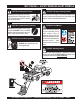
OPERATION AND PARTS MANUAL SERIES MODEL MVC-70H/HW ONE-WAY PLATE COMPACTOR (HONDA GASOLINE ENGINE) Revision #2 (11/02/05) To find the latest revision of this publication, visit our website at: www.multiquip.com THIS MANUAL MUST ACCOMPANY THE EQUIPMENT AT ALL TIMES.
PROPOSITION 65 l PAGE 2 — MVC-70H/HW PLATE COMPACTOR — OPERATION & PARTS MANUAL — REV.
NOTE PAGE MVC-70H/HW PLATE COMPACTOR — OPERATION & PARTS MANUAL — REV.
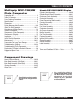
TABLE OF CONTENTS Multiquip MVC-70H/HW Plate Compactor Proposition 65 ........................................................... 2 Table Of Contents ..................................................... 4 Parts Ordering Procedures ....................................... 5 Specifications ............................................................ 6 Dimensions ............................................................... 7 Safety Message Alert Symbols ..............................
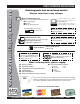
www.multiquip.com PARTS ORDERING PROCEDURES Ordering parts has never been easier! Choose from three easy options: Best Deal! Order via Internet (Dealers Only): If you have an MQ Account, to obtain a Username and Password, E-mail us at: parts@multiquip.com. Order parts on-line using Multiquip’s SmartEquip website! ■ View Parts Diagrams ■ Order Parts ■ Print Specification Information To obtain an MQ Account, contact your District Sales Manager for more information.
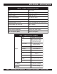
MVC-70H/HW — SPECIFICATIONS TABLE 1. COMPACTOR SPECIFICATIONS Model MVC-70H/W Centrifugal Force 1,220 kg (2,700 lbs.) Vibration Frequency 5,600 vpm (93 Hz) Maximum Forward Speed 25 m/min (82 ft/min) Plate Size (L x W) 541 x 350 mm (21.3 x 13.8 in ) Overall Dimensions (L x W x H) 879 x 350 x 886 mm (4.6 x 13.8 x 34.9 in ) Operating Weight (with water tank) 86 kg (190 lbs.) Operating Weight (without water tank) 76 kg (168 lbs.) Maximum Area of Compaction 543 sq. m/hr (5,865 sq.
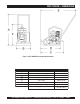
MVC-70H/HW — DIMENSIONS Figure 1. MVC-70H/HW Plate Compactor Dimensions TABLE 3. DIMENSIONS REFERENCE LETTER A B C D E F DESCRIPTION Height (Handle Upright) Width Length (Handle Upright) Plate Length Length (Handle Lowered) Height (Compactor Only) Shipping Dimensions DIMENSION in. (mm) 914 mm (36 in). 420 mm (16.5 in. 635 mm (25 in.) 510 mm (20 in). 914 mm (36 in). 635 mm (25 in.) 686 x 381 x 711 mm ( 27 x 15 x 28 in.) MVC-70H/HW PLATE COMPACTOR — OPERATION & PARTS MANUAL — REV.
MVC-70H/HW — SAFETY MESSAGE ALERT SYMBOLS FOR YOUR SAFETY AND THE SAFETY OF OTHERS! HAZARD SYMBOLS Safety precautions should be followed at all times when operating this equipment. Failure to read and understand the Safety Messages and Operating Instructions could result in injury to yourself and others. Potential hazards associated with the operation of the MQ Model MVC-70H/HW Plate Compactor.
MVC-70H/HW — SAFETY MESSAGE ALERT SYMBOLS CAUTION - Rotating Parts Hazards NEVER operate equipment with covers, or guards removed. Keep fingers, hands, hair and clothing away from all moving parts to prevent injury. CAUTION - Accidental Starting Hazards ALWAYS place the power source, circuit breakers or ON/OFF switch in the OFF position, when the generator is not in use, unless connected to transfer switch. CAUTION - Eye and Hearing Hazards ALWAYS wear approved eye and hearing protection.
MVC-70H/HW — RULES FOR SAFE OPERATION CAUTION - Read Manual! Failure to follow instructions in this manual may lead to serious injury or even death! This equipment is to be operated by trained and qualified personnel only! This equipment is for industrial use only. The following safety guidelines should always be used when operating the MQ Mikasa Model MVC-70H/HW Plate Compactor. GENERAL SAFETY ■ DO NOT operate or service this equipment before reading this entire manual.
MVC-70H/HW — RULES FOR SAFE OPERATION ■ NEVER run engine without air filter. Severe engine damage may occur. ■ ALWAYS service air cleaner frequently to prevent carburetor malfunction. ■ ALWAYS be sure the operator is familiar with proper safety precautions and operations techniques before using compactor. ■ ALWAYS read, understand, and follow procedures in Operator’s Manual before attempting to operate equipment. ■ Refer to the Honda Engine Owner's Manual for engine technical questions or information.
MVC-70H/HW — OPERATION AND SAFETY DECALS Machine Safety Decals The MVC-70H/HW Plate Compactor is equipped with a number of safety decals (Figure 2). These decals are provided for operator safety and maintenance information. The illustration below shows these decals as they appear on the machine. Should any of these decals become unreadable, replacements can be obtained from your dealer. l Figure 2. Operation and Safety Decals PAGE 12 — MVC-70H/HW PLATE COMPACTOR — OPERATION & PARTS MANUAL — REV.
MVC-70H/HW — GENERAL INFORMATION Definition of Plate Compactor Frequency/Speed The Mikasa MVC-70H/HW is a walk behind, plate compactor designed for the compaction of sand, mixed soils and asphalt. This plate compactor is a powerful compacting tool capable of applying a tremendous force in consecutive high frequency vibrations to a soil surface. Its applications include compacting for road, embankments and reservoirs as well as backfilling for gas pipelines, water pipelines and cable installation work.
MVC-70H/HW — COMPONENTS (PLATE COMPACTOR) Figure 3. MVC-70H/HW Plate Compactor Components Figure 3 shows the location of the components and general maintenance parts. The function of each component is described below: 6. Belt Cover – Remove this cover to gain acess to the Vbelts. NEVER run the compactor without the V-belt cover. If the V-belt cover is not installed, the possibility exist that your hand may get caught between the V-belt and clutch, thus causing serious injury and bodily harm. 1.
MVC-70H/HW — COMPONENTS (HONDA GX160K1QMX2 ENGINE) Figure 4. Engine Controls & Components 5. Fuel Valve Lever – OPEN to let fuel flow, CLOSE to stop the flow of fuel. 6. Choke Lever – Used in the starting of a cold engine, or in cold weather conditions. The choke enriches the fuel mixture. 7. Air Cleaner – Prevents dirt and other debris from entering the fuel system. Remove wing-nut on top of air filter cannister to gain access to filter element.
MVC-70H/HW — INSPECTION Before Starting 1. Read safety instructions at the beginning of manual. NOTE 2. Clean the compactor, removing dirt and dust. Particularly, the bottom of the plate, engine cooling air inlet, carburetor and air cleaner. 3. Check the air filter for dirt and dust. If the air filter is dirty, blow through the air filter cartridge from the inside, moving a jet of dry compressed air up and down until all dust is removed. Otherwise replace air filter with a new one. 4.
MVC-70H/HW — INSPECTION 2. The V-belt tension is proper if the V-belt bends 10 to 15 mm (Figure 10) when depressed with finger at midway between the clutch and vibration pulley shafts. V-Belt Check Caution - V-Belt check NEVER attempt to check the V-belt with the engine running. Severe injury can occur if your hand (Figure 8) gets caught between the V-belt and the clutch. Always use safety gloves. CLUTCH PULLEY Figure 10. V-Belt Tension VIBRATOR PULLEY 3.
MVC-70H/HW — INITIAL START-UP Caution - Read Manual NOTE D DO NOT attempt to operate the plate compactor until the Safety, General Information and Inspection sections of this manual have been read and thoroughly understood. 1. Place the fuel valve lever (Figure 11) in the "ON" position. The CLOSED position of the choke lever enriches the fuel mixture for starting a COLD engine. The OPEN position provides the correct fuel mixture for normal operation after starting, and for restarting a warm engine. 4.
MVC-70H/HW — INITIAL START-UP 6. If the engine has started, slowly return the choke lever (Figure 13) to the CLOSED position. If the engine has not started repeat steps 1 through 5. 7. Before the compactor is put into operation run the engine for 3-5 minutes. 8. Check for abnormal engine noises or fuel leaks. Stopping the Engine Caution - Stopping Engine NEVER stop the engine suddenly while working at high speeds. 1.
MVC-70H/HW — MAINTENANCE CAUTION - Inspection CAUTION - Inspection Intervals These inspection intervals are for operation under normal conditions. Adjust your inspection intervals based on the number of hours plate compactor is in use, and particular working conditions. Inspection and other services should always be carried out on hard and level ground with the engine shut down. Inspection and Maintenance Service Tables. 1.
MVC-70H/HW — MAINTENANCE Changing Vibrator Oil 1. When changing the vibrator oil, remove the drain plug (Figure 7), and simply tip the compactor to drain the oil. Note that the oil will drain more easily while it is hot. Remember to use only 10W-30 motor oil when replacing vibrator oil. Checking and Replacing the V-Belt and Clutch Figure 16. Engine Oil Plug Spark Plug 1. Remove and clean the spark plug (Figure 17). 2. Adjust the spark gap to 0.028 ~0.031 inch (0.6~0.7 mm).
MVC-70H/HW — PREPARATION FOR LONG -TERM STORAGE Compactor Storage For storage of the compactor for over 30 days, the following is required: z Drain the fuel tank completely. z Run the engine until the fuel in the injection system is completely consumed. z Completely drain the oil from the engine crankcase and follow procedures described in the HONDA engine Owner's Manual for engine storage. z Completely drain the compactor's oil from the vibrating case.
MVC-70H/HW — TROUBLESHOOTING (ENGINE) Practically all breakdowns can be prevented by proper handling and maintenance inspections, but in the event of a breakdown, please take a remedial action following the diagnosis based on the Troubleshooting Charts (Tables 8 and 9). If the problem cannot be remedied, please leave the unit just as it is and consult our company's business office or service plant. TABLE 8. ENGINE TROUBLESHOOTING SYMPTOM Difficult to start, "fuel is available, but no SPARK at spark plug".
MVC-70H/HW — TROUBLESHOOTING (ENGINE) TABLE 8. ENGINE TROUBLESHOOTING (CONTINUED) SYMPTOM "Weak in power" compression is proper and does not misfire. POSSIBLE CAUSE SOLUTION Air cleaner not clean? Clean or replace air cleaner Improper level in carburetor? Check float adjustment, re-build carbureator. Defective Spark plug? Clean or replace spark plug. Defective Spark plug? "Weak in power" compression is proper but misfires. Engine overheats. Rotational speed fluctuates.
MVC-70H/HW — TROUBLESHOOTING (PLATE COMPACTOR) TABLE 9. PLATE COMPACTOR TROUBLESHOOTING SYMPTOM Travel speed too low, and vibration is weak. Does not travel forward. POSSIBLE CAUSE SOLUTION Engine speed too low? Set engine speed to correct RPM. Clutch slips? Check or replace clutch. V-belt slips? Adjust or replace V-belt. Excessive oil in vibrator? Drain excess oil and fill to proper level. Malfunction in vibrator housing? Check eccentr ic, gears and counter weights.
MVC-70H/HW — EXPLANATION OF CODE IN REMARKS COLUMN The following section explains the different symbols and remarks used in the Parts section of this manual. Use the help numbers found on the back page of the manual if there are any questions. The contents and part numbers listed in the parts section are subject to change without notice. Multiquip does not guarantee the availibility of the parts listed. Sample Parts List: NO.
MVC-70H/HW — SUGGESTED SPARE PARTS MQ MIKASA MVC-70H/HW PLATE COMPACTOR WITH HONDA GX160K1QMX2 GASOLINE ENGINE 1 to 3 Units Qty. P/N Description 3 .......... 070100312 ........... V-BELT 4 .......... 939010250 ........... SHOCK ABSORBER 3 .......... 9807956846 ......... SPARK PLUG 1 .......... 28462ZH8003 ...... ROPE, RECOIL STARTER 3 .......... 17210ZE1505 ....... ELEMENT, AIR CLEANER 1 .......... 17620ZH7023 ...... FUEL CAP 1 .......... 17672ZE2W01 .....
MVC-70H/HW — NAME PLATE AND DECALS NAME PLATE AND DECALS l PAGE 28 — MVC-70H/HW PLATE COMPACTOR — OPERATION & PARTS MANUAL — REV.
MVC-70H/HW — NAME PLATE AND DECALS NAMEPLATE AND DECALS NO. PART NO. PART NAME QTY. REMARKS 1 PLATE, MODEL/SERIAL NUMBER ..................... 1 ................ CONTACT PARTS DEPT. 2 920203290 DECAL, READ OWNERS MANUAL 1 ................ NPA-329 3 920203989 DECAL, BELT GUARD WARNING 1 ................ NPA-989 4 920101410 DECAL: MIKASA MARK 120X60 ......................... 1 ................ WATER TANK 5 920201580 DECAL: MQ MARK 71X55 ................................... 1 ................
MVC-70H/HW — MAIN BODY ASSY. (OLD STYLE) MAIN BODY ASSY. (OLD STYLE) l PAGE 30 — MVC-70H/HW PLATE COMPACTOR — OPERATION & PARTS MANUAL — REV.
MVC-70H/HW — MAIN BODY ASSY. (OLD STYLE) MAIN BODY ASSY. (OLD STYLE) NO PART NO PART NAME QTY. REMARKS 1 418117720 VIBRATORY PLATE .................................. 1 ................. S/N L1643 AND BELOW 2 418216500 BASE ........................................................ 1 ................. S/N L1663 AND BELOW 3 939010250 SHOCK ABSORBER D45-H41 4 4 959404350 EARTH WIRE 1 5 020310080 NUT M10 8 6 030210250 WASHER, LOCK M10 8 7 031110160 WASHER, FLAT M10 4 8 939010010 SHOCK ABSORBER, STOPPER 45 .......
MVC-70H/HW — MAIN BODY ASSY. (NEW STYLE) MAIN BODY ASSY. (NEW STYLE) l PAGE 32 — MVC-70H/HW PLATE COMPACTOR — OPERATION & PARTS MANUAL — REV.
MVC-70H/HW — MAIN BODY ASSY. (NEW STYLE) MAIN BODY ASSY. (NEW STYLE) NO PART NO PART NAME QTY. REMARKS 1 418117721 VIBRATORY PLATE .................................. 1 ................. S/N L1644 AND ABOVE 2 418216501 BASE ........................................................ 1 .................
MVC-70H/HW — VIBRATOR ASSY. VIBRATOR ASSY. l PAGE 34 — MVC-70H/HW PLATE COMPACTOR — OPERATION & PARTS MANUAL — REV.
MVC-70H/HW — VIBRATOR ASSY. VIBRATOR ASSY. NO 61 62 63 64 65 66 67 68 69 70 71 72 72 73 74 75 77 78 79 PART NO 418117730 001221445 030214350 031114260 418456950 060403020 418456960 418456970 002400820 418456990 418343400 040306307 040406307 418456980 951401920 952403450 002211030 953400270 953405260 PART NAME VIBRATING CASE BOLT 14X45 T WASHER, LOCK M14 WASHER, FLAT M14 CASE COVER/PULLEY OIL SEAL TC-30458 CASE COVER/SHUT-OFF PACKING BOLT 8X20 SW, PW COVER SEAL, VIB. ECC.
MVC-70H/HW — WATER TANK ASSY. WATER TANK ASSY. l PAGE 36 — MVC-70H/HW PLATE COMPACTOR — OPERATION & PARTS MANUAL — REV.
MVC-70H/HW — WATER TANK ASSY. WATER TANK ASSY. NO 91 92 101 101 102 * 103 * 104 * 105 * 107 108 110 111 112 113 114 115 PART NO 418216510 002211025 418910020 418910030 954300342 001241030 033910010 022910180 954403241 959403790 416338940 418343430 001220825 031108160 020308060 418457010 PART NAME QTY. REMARKS HOOK 1 BOLT 10X25 H, SW 3 WATER TANK, ORANGE ........................... 1 ................. INCLUDES ITEM W/ * WATER TANK, WHITE ............................... 1 .................
HONDA GX160K1QMX2 ENGINE — CYLINDER HEAD ASSY. CYLINDER HEAD ASSY. l PAGE 38 — MVC-70H/HW PLATE COMPACTOR — OPERATION & PARTS MANUAL — REV.
HONDA GX160K1QMX2 ENGINE — CYLINDER HEAD ASSY. CYLINDER HEAD ASSY. NO. PART NO. 1 12210ZH8000 2 * 12204ZE1306 3 * 12205ZE1315 4 # 12216ZE5300 * 5 12251ZF1800 6 12310ZE1010 7 12391ZE1000 8 15721ZH8000 9 90016ZE1000 10 90043ZE1020 11 90047ZE1000 12 9430110160 14 957230806000 15 9807955846 15 9807956846 PART NAME QTY. REMARKS CYLINDER HEAD......................................... 1 ...... INCLUDES ITEMS W/ * GUIDE, VALVE (OS) (OPTIONAL) 1 GUIDE, EX. VALVE (OS) (OPTIONAL) ........ 1 ......
HONDA GX160K1QMX2 ENGINE — CYLINDER BARREL ASSY. CYLINDER BARREL ASSY. l PAGE 40 — MVC-70H/HW PLATE COMPACTOR — OPERATION & PARTS MANUAL — REV.
HONDA GX160K1QMX2 ENGINE — CYLINDER BARREL ASSY. CYLINDER BARREL ASSY. NO. PART NO. 2 12000ZH8811 3 15510ZE1023 3 15510ZE1033 4 16510ZE1000 5# 16511ZE1000 16512ZE1000 6# 8 16531ZE1000 10 90131ZE1000 11 90451ZE1000 12 90601ZE1000 13 90602ZE1000 14 * 91001ZF1003 15 91202883005 * 16 91353671003 17 9405010000 18 9410106800 19 9425108000 20 957010601200 PART NAME QTY. REMARKS CYLINDER ASSY. (OIL ALERT) ................... 1 ...... INCLUDES ITEMS W/ * SWITCH ASSY., OIL LEVEL ........................ 1 ......
HONDA GX160K1QMX2 ENGINE — CRANKCASE COVER ASSY. CRANKCASE COVER ASSY. l PAGE 42 — MVC-70H/HW PLATE COMPACTOR — OPERATION & PARTS MANUAL — REV.
HONDA GX160K1QMX2 ENGINE — CRANKCASE COVER ASSY. CRANKCASE COVER ASSY. NO. PART NO. 1 11300ZE1641 3 11381ZH8801 4 15600ZE1003 5 15600ZG4003 9# 15625ZE1003 15625ZE1003 10+ 11 91202883005 * 12 9430108140 13 957010803200 961006205000 14 * PART NAME QTY. REMARKS COVER ASSY., CRANKCASE (U-TYPE) ..... 1 ...... INCLUDES ITEMS W/ * GASKET, CASE COVER 1 CAP ASSY., OIL FILLER ............................. 1 ...... INCLUDES ITEMS W/# CAP ASSY., OIL FILLER ............................. 1 ......
HONDA GX160K1QMX2 ENGINE — CRANKSHAFT ASSY. CRANKSHAFT ASSY. l PAGE 44 — MVC-70H/HW PLATE COMPACTOR — OPERATION & PARTS MANUAL — REV.
HONDA GX160K1QMX2 ENGINE — CRANKSHAFT ASSY. CRANKSHAFT ASSY. NO. PART NO. 4 13310ZE1601 13 90003ZE1000 14 90473842000 15 90745ZE1600 PART NAME QTY. REMARKS CRANKSHAFT (Q-TYPE) 1 BOLT, HEX 5/16” ............................................ 1 .... USE FROM S/N 6745959 WASHER, 8 MM ............................................. 1 .... USE FROM S/N 6745959 KEY, 78 X 38 MM 1 MVC-70H/HW PLATE COMPACTOR — OPERATION & PARTS MANUAL — REV.
HONDA GX160K1QMX2 ENGINE — PISTON/RINGS ASSY. PISTON/RINGS ASSY. l PAGE 46 — MVC-70H/HW PLATE COMPACTOR — OPERATION & PARTS MANUAL — REV.
HONDA GX160K1QMX2 ENGINE — PISTON/RINGS ASSY. PISTON/RINGS ASSY. NO. PART NO. 1 13010ZH8941 1 13011ZH8941 1 13012ZH8941 1 13013ZH8941 2 13101ZH8000 2 13102ZH8000 2 13103ZH8000 2 13104ZH8000 3 13111ZE1000 4 13200ZE1010 5 90001ZE1000 * 90551ZE1000 6 PART NAME QTY. REMARKS RING SET, PISTON (STD) 1 RING SET, PISTON (OS 0.25) 1 RING SET, PISTON (OS 0.50) ............. 1 ......... USE FROM ENGINE S/N 4733211 RING SET, PISTON (0.75) OPTION 1 PISTON (STD) 1 PISTON (OS 0.25) 1 PISTON (OS 0.50) 1 PISTON (0.
HONDA GX160K1QMX2 ENGINE — CAMSHAFT ASSY. CAMSHAFT ASSY. l PAGE 48 — MVC-70H/HW PLATE COMPACTOR — OPERATION & PARTS MANUAL — REV.
HONDA GX160K1QMX2 ENGINE — CAMSHAFT ASSY. CAMSHAFT ASSY. NO. PART NO. 1 14100ZE1812 2 14410ZE1010 3 14431ZE1000 4 14441ZE1010 5 14451ZE1013 6 * 14568ZE1000 7 14711ZF1000 8 14721ZF1000 9 14751ZF1000 10 14771ZE1000 11 14773ZE1000 12 14781ZE1000 13 14791ZE1010 14 90012ZE0010 15 90206ZE1000 PART NAME QTY. REMARKS CAMSHAFT ASSY. ...................................... 1 ...... INCLUDES ITEMS W/ * ROD, PUSH 2 ARM, VLAVE ROCKER 2 LIFTER, VALVE 2 PIVOT, ROCKER ARM 2 SPRING, WEIGHT RETURN 1 VALVE, IN. 1 VALVE, EX.
HONDA GX160K1QMX2 ENGINE — RECOIL STARTER ASSY. RECOIL STARTER ASSY. l PAGE 50 — MVC-70H/HW PLATE COMPACTOR — OPERATION & PARTS MANUAL — REV.
HONDA GX160K1QMX2 ENGINE — RECOIL STARTER ASSY. RECOIL STARTER ASSY. NO. PART NO. 1 28400ZH8013ZB 2 28410ZH8003ZB * 3 * 28420ZH8013 4 * 28422ZH8013 5 * 28433ZH8003 6 * 28441ZH8003 7 28442ZH8003 * 8 * 28443ZH8003 9 * 28461ZH8003 28462ZH8003 10 * 11 * 90003ZH8003 12 90008ZE2003 PART NAME QTY. REMARKS STARTER ASSY., RECOIL “NH1”(BLACK) ............ 1 .....
HONDA GX160K1QMX2 ENGINE — FAN COVER ASSY. FAN COVER ASSY. l PAGE 52 — MVC-70H/HW PLATE COMPACTOR — OPERATION & PARTS MANUAL — REV.
HONDA GX160K1QMX2 ENGINE — FAN COVER ASSY. FAN COVER ASSY. NO. PART NO. 2 19610ZE1000ZC 4 19612ZH8811 7 90601ZH7013 8 19630ZH8000 11 36100ZE1015 11 36100ZH7003 13 90013883000 14 90022888010 17 34150ZH7003 19 957010600800 PART NAME QTY. REMARKS COVER, FAN *NH1* (BLACK) 1 PLATE, SIDE (OIL ALERT) 1 CLIP, HARNESS 1 SHROUD 1 SWITCH ASSY., ENGINE STOP ........... 1.......... USE UP TO S/N 4368640 SWITCH ASSY., ENGINE STOP ........... 1..........
HONDA GX160K1QMX2 ENGINE — CARBURETOR ASSY. CARBURETOR ASSY. l PAGE 54 — MVC-70H/HW PLATE COMPACTOR — OPERATION & PARTS MANUAL — REV.
HONDA GX160K1QMX2 ENGINE — CARBURETOR ASSY. CARBURETOR ASSY. NO. PART NO.
HONDA GX160K1QMX2 ENGINE — AIR CLEANER ASSY. AIR CLEANER ASSY. l PAGE 56 — MVC-70H/HW PLATE COMPACTOR — OPERATION & PARTS MANUAL — REV.
HONDA GX160K1QMX2 ENGINE — AIR CLEANER ASSY. AIR CLEANER (DUAL) ASSY. NO. PART NO. 1 16271ZE1000 2 17210ZE1505 3 * 17218ZE1505 4 17230ZE1820 5 * 17232891000 17238ZE7010 6# 7# 17239ZE1000 8 17410ZE1020 9 90201415000 10 17235ze1831 11 90325044000 13 957010602000 PART NAME QTY. REMARKS GASKET, ELBOW ........................................ 1 ......
HONDA GX160K1QMX2 ENGINE — MUFFLER ASSY. MUFFLER ASSY. l PAGE 58 — MVC-70H/HW PLATE COMPACTOR — OPERATION & PARTS MANUAL — REV.
HONDA GX160K1QMX2 ENGINE — MUFFLER ASSY. MUFFLER ASSY. NO. PART NO. 1 18310ZH8810 1 18310ZK8V50 3 18320ZF1H01 5 18331883810 7 18355ZE1000 8 18381ZH8800 11 90050ZE1000 12 90055ZE1000 13 18522ZE1000 15 94001080000S 30 90002ZG0003 PART NAME QTY. REMARKS MUFFLER..................................................... 1 ...... USE UP TO S/N 6745959 MUFFLER..................................................... 1 ......
HONDA GX160K1QMX2 ENGINE — FUEL TANK ASSY. FUEL TANK ASSY. l PAGE 60 — MVC-70H/HW PLATE COMPACTOR — OPERATION & PARTS MANUAL — REV.
HONDA GX160K1QMX2 ENGINE — FUEL TANK ASSY. FUEL TANK ASSY. NO. PART NO. 10 16854ZH8000 17 16955ZE1000 20 17510ZE1020ZF 21 17620ZH7023 23 17631ZH7003 * 17672ZE2W01 24 29 91353671003 33 9405006000 36 950014500360M 40 43 44 45 9500202080 957010602500 90404680000 91319ME5003 PART NAME QTY. REMARKS RUBBER, SUPPORTER (107MM) 1 JOINT, FUEL TANK 1 TANK, FUEL *NH1* (BLACK) 1 CAP, FUEL FILLER ...................................... 1 ...... INCLUDES ITEMS W/ * GASKET, FUEL FILLER CAP 1 FILTER, FUEL 1 O-RING (13.
HONDA GX160K1QMX2 ENGINE — FLYWHEEL ASSY. FLYWHEEL ASSY. l PAGE 62 — MVC-70H/HW PLATE COMPACTOR — OPERATION & PARTS MANUAL — REV.
HONDA GX160K1QMX2 ENGINE — FLYWHEEL ASSY. FLYWHEEL ASSY. NO. PART NO. 1 13331357000 2 19511ZE1000 4 28451ZH8003 5 31100ZE1010 5 31100ZE1810 8 90201878003 PART NAME KEY, SPECIAL WOODRUFF (25 X 18) FAN, COOLING PULLEY, STARTER FLYWHEEL FLYWHEEL (LAMP) NUT, SPECIAL (14MM) QTY. 1 1 1 1 1 1 REMARKS MVC-70H/HW PLATE COMPACTOR — OPERATION & PARTS MANUAL — REV.
HONDA GX160K1QMX2 ENGINE — IGNITION COIL ASSY. IGNITION COIL ASSY. l PAGE 64 — MVC-70H/HW PLATE COMPACTOR — OPERATION & PARTS MANUAL — REV.
HONDA GX160K1QMX2 ENGINE — IGNITION COIL ASSY. IGNITION COIL ASSY. NO. PART NO. 1 30500ZE1033 2 30700ZE1013 7 36101ZE1010 11 90121952000 PART NAME COIL ASSY., IGNITION CAP ASSY., NOISE SUPPRESSOR WIRE, STOP SWITCH (370MM) BOLT, FLANGE (6 X 25) QTY. 1 1 1 2 REMARKS MVC-70H/HW PLATE COMPACTOR — OPERATION & PARTS MANUAL — REV.
HONDA GX160K1QMX2 ENGINE — CONTROL ASSY. CONTROL ASSY. l PAGE 66 — MVC-70H/HW PLATE COMPACTOR — OPERATION & PARTS MANUAL — REV.
HONDA GX160K1QMX2 ENGINE — CONTROL ASSY. CONTROL ASSY. NO. PART NO. 2 16500ZH8813 4 16551ZE0010 5 16555ZE1000 6 16561ZE1020 7 16562ZE1020 9 * 16571ZH8020 10 16574ZE1000 * 11 * 16575ZH8000 12 * 16576891000 16578ZE1000 13 * 14 * 16580ZH8813 15 * 16584883300 16 * 16592ZE1810 17 * 16594883010 21 90013883000 22 90015ZE5010 24 90114SA0000 * 93500050250H 25 * 90605230000 26 * 93500040060H 27 * 93500050160A 28 * 9405006000 29 PART NAME QTY. REMARKS CONTROL ASSY. ......................................... 1 ......
HONDA GX160K1QMX2 ENGINE — GASKET KIT ASSY. NO ARTWORK AVAILABLE l PAGE 68 — MVC-70H/HW PLATE COMPACTOR — OPERATION & PARTS MANUAL — REV.
HONDA GX160K1QMX2 ENGINE — GASKET KIT ASSY. GASKET KIT ASSY. NO. PART NO. 1 06111ZH8405 2 11381ZH8801 * 3 * 12251ZF1800 4 * 12391ZE1000 5 * 16212ZH8800 6 * 16221ZH8801 7 18381ZH8800 * PART NAME QTY. REMARKS GASKET KIT ............................................. 1 .......... INCLUDES ITEMS W/ * GASKET, CASE COVER 1 GASKET, CYLINDER HEAD 1 GASKET, CYLINDER HEAD COVER 1 GASKET, INSULATOR 1 GASKET, CARBURETOR 1 GASKET, MUFFLER 1 MVC-70H/HW PLATE COMPACTOR — OPERATION & PARTS MANUAL — REV.
HONDA GX160K1QMX2 ENGINE — LABELS ASSY. LABELS ASSY. l PAGE 70 — MVC-70H/HW PLATE COMPACTOR — OPERATION & PARTS MANUAL — REV.
HONDA GX160K1QMX2 ENGINE — LABELS ASSY. LABELS ASSY. NO. PART NO. 1 87521ZH8020 3 87522zh9010 6 87528ZE1810 8 87532ZH8810 PART NAME EMBLEM (5.5) LABEL, CAUTION MARK, CHOKE MARK, OIL ALERT (E) QTY. 1 1 1 1 REMARKS MVC-70H/HW PLATE COMPACTOR — OPERATION & PARTS MANUAL — REV.
TERMS AND CONDITIONS OF SALE — PARTS Effective: October 1, 2002 PAYMENT TERMS 5. Parts must be in new and resalable condition, in the original Multiquip package (if any), and with Multiquip part numbers clearly marked. 6. The following items are not returnable: Terms of payment for parts are net 10 days. FREIGHT POLICY All parts orders will be shipped collect or prepaid with the charges added to the invoice. All shipments are F.O.B. point of origin.
NOTE PAGE MVC-70H/HW PLATE COMPACTOR — OPERATION & PARTS MANUAL — REV.
OPERATION AND PARTS MANUAL HERE'S HOW TO GET HELP PLEASE HAVE THE MODEL AND SERIAL NUMBER ON-HAND WHEN CALLING UNITED STATES Multiquip Corporate Office 18910 Wilmington Ave. Tel. (800) 421-1244 Carson, CA 90746 Fax (800) 537-3927 Contact: mq@multiquip.com Mayco Parts 800-306-2926 Fax: 800-672-7877 310-537-3700 Fax: 310-637-3284 Service Department 800-421-1244 Fax: 310-537-4259 310-537-3700 MQ Parts Department 800-427-1244 310-537-3700 MEXICO UNITED KINGDOM MQ Cipsa Carr. Fed. Mexico-Puebla KM 126.