OPERATION & PARTS MANUAL SERIES MODEL MVH-200DA REVERSIBLE PLATE COMPACTOR (YANMAR DIESEL ENGINE) Revision #0 (03/21/05) THIS MANUAL MUST ACCOMPANY THE EQUIPMENT AT ALL TIMES.
PAGE 2 — MVH-200DA PLATE COMPACTOR — OPERATION & PARTS MANUAL — REV.
HERE'S HOW TO GET HELP PLEASE HAVE THE MODEL AND SERIAL NUMBER ON-HAND WHEN CALLING MULTIQUIP CORPORATE OFFICE 18910 Wilmington Ave. Carson, CA 90746 Email: mq@multiquip.com Internet: www.multiquip.com PARTS DEPARTMENT 800-427-1244 310-537-3700 MAYCO PARTS 800-306-2926 310-537-3700 SERVICE DEPARTMENT 800-421-1244 310-537-3700 TECHNICAL ASSISTANCE 800-478-1244 WARRANTY DEPARTMENT 800-421-1244, EXT. 279 310-537-3700, EXT.
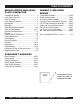
TABLE OF CONTENTS MIKASA SERIES MVH-200DA PLATE COMPACTOR YANMAR L70EE-DVMK ENGINE Proposition 65 Warning ............................................. 2 Here’s How To Get Help ............................................ 3 Table Of Contents ..................................................... 4 Parts Ordering Procedures ....................................... 5 Specifications ............................................................ 6 Dimensions .......................................................
PARTS ORDERING PROCEDURES When ordering parts, please supply the following information: ❒ ❒ ❒ ❒ ❒ ❒ ❒ Dealer account number Dealer name and address Shipping address (if different than billing address) Return fax number Applicable model number Quantity, part number and description of each part Specify preferred method of shipment: Note: Unless otherwise indicated by customer, all ✓ FedEx or UPS Ground orders are treated as “Standard Orders”, and will ✓ FedEx or UPS Second Day or Third Day ship within 24 hou
MVH-200DA — SPECIFICATIONS Table 1. MVH-200DA REVERSIBLE PLATE COMPACTOR SPECIFICATIONS Centrifugal Force 7,056 lbs. (3,200 kg) Vibration Frequency 5,200 vpm Maximum Forward Speed 75 ft/min (23 m/min) Plate Size (L x W) 27.6 x 20 in (70 x 51 cm) Operating Weight 449 lbs. (204 kg) Maximum Area Capacity 7,515 sq. ft/hr (698 sq. m/hr) HP Rating 6.7 BHP (4.9 kW) Table 2.
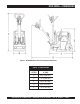
MVH-200DA — DIMENSIONS Figure 1. MVH-200DA Reversible Plate Compactor Dimensions TABLE 3. DIMENSIONS REFERENCE LETTER DIMENSIONS IN. (MM) A 49 in. (1245 mm.) B 21 in. (533 mm.) C 26.5 in. (673 mm.) D 48 in. (1219 mm.) E 31 in. (787 mm.) MVH-200DA PLATE COMPACTOR — OPERATION & PARTS MANUAL — REV.
MVH-200DA — SAFETY MESSAGE ALERT SYMBOLS FOR YOUR SAFETY AND THE SAFETY OF OTHERS! Safety precautions should be followed at all times when operating this equipment. Failure to read and understand the Safety Messages and Operating Instructions could result in injury to yourself and others. NOTE This Owner's Manual has been developed to provide complete instructions for the safe and efficient operation of the Multiquip Model MVH-200DA Reversible Plate Compactor.
MVH-200DA — SAFETY MESSAGE ALERT SYMBOLS CAUTION - Rotating Parts CAUTION - Equipment Damage Messages NEVER operate equipment with covers, or guards removed. Keep fingers, hands, hair and clothing away from all moving parts to prevent injury. Other important messages are provided throughout this manual to help prevent damage to your light tower, other property, or the surrounding environment.
MVH-200DA — RULES FOR SAFE OPERATION DANGER Failure to follow instructions in this manual may lead to serious injury or even death! This equipment is to be operated by trained and qualified personnel only! This equipment is for industrial use only. The following safety guidelines should always be used when operating the compactor: GENERAL SAFETY ■ DO NOT operate or service this equipment before reading this entire manual. ■ This equipment should not be operated by persons under 18 years of age.
MVH-200DA — RULES FOR SAFE OPERATION Loading and Unloading (Crane): ■ Before lifting, make sure that machine parts (hook and vibration insulator) are not damaged and screws are not loosened or lost. ■ Always make sure crane or lifting device has been properly secured to the hook of guard frame on compactor. ■ NEVER lift the machine while the engine is running. ■ Use adequate lifting cable (wire or rope) of sufficient strength. ■ Use one point suspension hook and lift straight upwards.
MVH-200DA — OPERATION AND SAFETY DECALS Figure 2 displays the operation and safety decals as they appear on the reversible plate compactor. Should any of these decals become damaged or unreadable, contact the Multiquip Parts Department for a replacement set. Figure 2. Operation and Safety Decals PAGE 12 — MVH-200DA PLATE COMPACTOR — OPERATION & PARTS MANUAL — REV.
MVH-200DA — FEATURES Plate Compactor Frequency/Speed The Mikasa MVH-200DA is a walk-behind, reversible plate compactor designed for the compaction of sand, clay and asphalt. This plate compactor is a powerful compacting tool capable of applying a tremendous force in consecutive high frequency vibrations to a soil surface. Its applications include soil compacting for road, embankments and reservoirs as well as backfilling for gas pipelines, water pipelines and cable installation work.
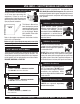
MVH-200DA — PLATE COMPACTOR COMPONENTS Figure 3. MVH-200DA Components Figure 3 illustrates the location of the major components for the 6. MVH-200DA Reversible Plate Compactor. The function of each component is described below: Engine –This plate compactor uses a YANMAR L70EEDVMK engine. Refer to the owner’s manual for engine information and related topics. 7. Belt Cover – Remove this cover to gain access to the Vbelts. NEVER run the compactor without the V-belt cover.
MVH-200DA — ENGINE COMPONENTS Figure 4. Engine Controls and Components The engine shown above is a YANMAR L70EE- DVMK engine 6. (Figure 4). The engine must be checked for proper lubrication and filled with fuel prior to operation. Refer to the manufacturer’s 7. engine manual for instructions and details of operation and servicing. Each component is described below: 1. Fuel Filler Cap – Remove this cap to add unleaded gasoline to the fuel tank. Make sure cap is tightened securely. DO NOT over fill.
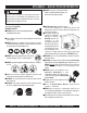
MVH-200DA — PRE-INSPECTION CAUTION - General Safety Precautions NEVER operate the compactor in a confined area or enclosed area structure that does not provide ample free flow of air. 3. Insert and remove the dipstick without screwing it into the filler neck. Check the oil level shown on the dipstick. 4. If the oil level is low (Figure 6), fill to the edge of the oil filler hole with the recommended oil type (Table 4). Maximum oil capacity is 1.16 quarts (1.1 liters).
MVH-200DA — START-UP PROCEDURE This section is intended to assist the operator with the initial start-up of the compactor. It is extremely important that this section be read carefully before attempting to use the compactor in the field. 4. Push down the decompression lever (Figure 10) and release. Starting the Engine (Yanmar engine): 1. Open the fuel cock (Figure 7). Figure 10. Decompression Lever 5. If the engine does not start, repeat steps 3 and 4. Shut-Down Procedure: Figure 7. Fuel Cock 2.
MVH-200DA — OPERATION Emergency Shutdown Procedure: To Turn The Compactor: 1. Move the throttle lever quickly to the STOP position (Figure 11). 1. Move the travel lever to the NEUTRAL position. 2. Close the fuel cock. 2. Hold the hand grip firmly and turn the compactor in the desired direction. DO NOT swing compactor while gripping the travel lever. Traveling: 1. Grasp the compactor's hand grip and move the throttle lever (Figure 12) quickly to the fast position.
MVH-200DA — OPERATION Stowing the Handle: Lifting: 1. Push up the handle (Figure 15). 1. Use a crane or lift to load and unload the machine. A skilled crane operator is required to perform the job. 2. Pull the stopper grip upward into the hole of the guard frame to lock the handle. 2. When lifting the machine, check for any damaged or loose bolts, lifting hooks, and shock mounts. 3. Check any damaged or loose bolts in the guard frame to avoid machine sliding off. 4.
MVH-200DA — MAINTENANCE CAUTION - General Maintenance Safety Inspection and other services should always be carried out on hard and level ground with the engine shutdown. TABLE 6.
MVH-200DA — MAINTENANCE Engine Oil Replacement: 1. Replace engine oil, first in 25 hours of operation and every 50 to 100 hours afterwards. 2. Drain the engine oil when the oil is warm as shown in Figure 16. 3. Clean foam element in warm, soapy water or nonflammable solvent. Rinse and dry thoroughly. Dip the element in clean engine oil and completely squeeze out the excess oil from the element before installing. Figure 17. Engine Air Filter Figure 16. Engine Oil (Draining) 3.
MVH-200DA — MAINTENANCE Checking and Replacing the V-Belt and Clutch: Checking the Clutch After 200 hours of operation, remove the belt cover to check the V-belt tension (Figure 19). 1. With belt cover removed, visually check outer drum of the clutch for seizure and "V" groove for wear or damage. 2. Clean the "V" groove as necessary. 3. Check the clutch lining and shoe for signs of wear. If the shoe is worn, replace the clutch to prevent deficient power transmission and slippage. Replacing the Clutch 1.
MVH-200DA — MAINTENANCE CAUTION - Filling the Hydraulic Oil Reservoir Make sure hydraulic oil i is at a normal safe operating level. DO NOT over fill. Over filling (excessive oil) will cause excess oil to blow out of breather plug. Replacing Hydraulic Oil 1. Remove the hydraulic hoses (left and right) which enters the cylinder of the vibrator from the hydraulic pump and move the travel lever back and forth to drain the hydraulic oil from the pump. 2.
MVH-200DA — MAINTENANCE 6. Filling the reverse travel circuit with oil. a. With the travel lever pushed forward (hydraulic circuit is connected with reverse travel circuit), add oil into pump and remove bleed plug of vibrator cylinder (opposite of belt cover side). In a few seconds, oil will come out of bleed plug. b. When aeration disappears, reinstall the plug tightly. c. Move the travel lever slowly until aeration in the hand pump disappears (about 10 to 15 times). 7.
MVH-200DA — ENGINE TROUBLESHOOTING Practically all breakdowns can be prevented by proper handling and maintenance inspections, but in the event of a breakdown, please take remedial action following the diagnosis based on the Engine Troubleshooting Table (Table 8) information shown below and on the following page. If the problem cannot be remedied, please leave the unit as it is and consult Multiquip’s business office or service plant. TABLE 8.
MVH-200DA — PLATE COMPACTOR TROUBLESHOOTING Practically all breakdowns can be prevented by proper handling and maintenance inspections, but in the event of a breakdown, please take remedial action following the diagnosis based on the Compactor Troubleshooting Table (Table 9) information shown below. If the problem cannot be remedied, please leave the unit as it is and consult Multiquip’s business office or service plant. TABLE 9.
NOTE PAGE MVH-200DA PLATE COMPACTOR — OPERATION & PARTS MANUAL — REV.
EXPLANATION OF CODE IN REMARKS COLUMN How to read the marks and remarks used in this parts book. NOTE Items Found In the “Remarks” Column Serial Numbers-Where indicated, this indicates a serial number range (inclusive) where a particular part is used. If more than one of the same reference number is listed, the last one listed indicates newest (or latest) part available.
SUGGESTED SPARE PARTS MQ MIKASA MVH-200DA 1 to 3 Units W/ YANMAR L70EE- DVMK Qty. P/N Description 3 ......... 070200323 ....... V-BELTS 2 ......... 956100038 ....... THROTTLE WIRE 3 ......... 11465012591 ... ELEMENT, A/C 1 ......... 11428855041 ... CAP, FUEL TANK 1 ......... 11487076630 ... ROPE, RECOIL STARTER 2 ......... 11425035110 ... STRAINER, OIL LUB W/ O-RING 2 ......... 11425055121 ... FILTER, FUEL OIL 1 ......... 11425055100 ...
MVH-200DA — DECAL PLACEMENT BODY ASSY. PAGE 30 — MVH-200DA PLATE COMPACTOR — OPERATION & PARTS MANUAL — REV.
MVH-200DA — DECALS PLACEMENT BODY ASSY. NO. 1 2 3 4 5 6 7 8 9 10 11 12 13 PART NO. 920203260 920204230 920203330 920202220 920204580 920204040 920203290 920203560 920206280 920206290 TBD 920206880 PART NAME QTY. REMARKS DECAL, OIL TANK 1 DECAL, TRAVEL LEVER OP.
MVH-200DA — BODY ASSY. BODY ASSY. PAGE 32 — MVH-200DA PLATE COMPACTOR — OPERATION & PARTS MANUAL — REV.
MVH-200DA — BODY ASSY. BODY ASSY.
MVH-200DA — VIBRATION ASSY. VIBRATION ASSY. PAGE 34 — MVH-200DA PLATE COMPACTOR — OPERATION & PARTS MANUAL — REV.
MVH-200DA — VIBRATION ASSY. VIBRATION ASSY.
MVH-200DA — VIBRATION ASSY. (CONT.) VIBRATION ASSY. (CONT.) PAGE 36 — MVH-200DA PLATE COMPACTOR — OPERATION & PARTS MANUAL — REV.
MVH-200DA — VIBRATION ASSY. (CONT.) VIBRATION ASSY. (CONT.) NO PART NO 86 455324870 86 455331070 87 951404500 87 951405370 88 455324880 89 080200500 90 060105030 91 455324890 92 050100850 93 001220825 94 030208200 96 455324900 96 455335560 97 951403090 98 455435060 98 455448970 99 001221230 100 030212300 101 455324910 102 001521225 103 001521240 104 952405480 PART NAME QTY. REMARKS ROTARY SHAFT, DRIVE ........................... 1 ................. S/N 1540 AND BELOW ROTARY SHAFT, DRIVE ...................
MVH-200DA — CONTROL ( A-TYPE ) ASSY. CONTROL ( A-TYPE ) ASSY. PAGE 38 — MVH-200DA PLATE COMPACTOR — OPERATION & PARTS MANUAL — REV.
MVH-200DA — CONTROL ( A-TYPE ) ASSY. CONTROL ( A-TYPE ) ASSY.
MVH-200DA — PUMP ( A-TYPE ) ASSY. PUMP ( A-TYPE ) ASSY. PAGE 40 — MVH-200DA PLATE COMPACTOR — OPERATION & PARTS MANUAL — REV.
MVH-200DA — PUMP ( A-TYPE ) ASSY. PUMP NO A B * C * 1 * 2$ * 3$ * 5 * 6 * 7 * 8 * 9 * 10 * 11 * 12 * 13 * 14 * 15 * 16 * 17 * 18# * 19 #$ * 20# * 21# * 22 #$ * 22 #$ * 23 * 23-1 $ * 24 * 25 * 26 * 27 * 28 * 29 * 30 * 31 #$ * 32 * 33 * 34 * ( A-TYPE ) ASSY.
MVH-200DA — THROTTLE LEVER ( A-TYPE ) ASSY. THROTTLE ( A-TYPE ) ASSY. PAGE 42 — MVH-200DA PLATE COMPACTOR — OPERATION & PARTS MANUAL — REV.
MVH-200DA — THROTTLE LEVER ( A-TYPE ) ASSY. THROTTLE ( A-TYPE ) ASSY. NO PART NO PART NAME QTY. REMARKS 1 956200010 THROTTLE LEVER ASSY. 103F/SX 1 2 092008016 SCREW 8 X 16 2 2 092008025 SCREW 8 X 25 2 3 030208200 WASHER, LOCK 8MM 2 4 020108060 NUT M8 ..................................................... 2 ................. REPLACES 020308060 5 455435000 SPACER 7 X 9.5 X15 1 6 456331120 LEVER BRACKET, T ................................. 1 .................
YANMAR L70EE-DVMK— CYLINDER BLOCK ASSY. CYLINDER BLOCK ASSY. 1 2 NOTES: 1 2 - SEE CYLINDER HEAD AND BONNET ASSY., ITEM1 - SEE FUEL INJECTION PUMP ASSY., ITEM1 PAGE 44 — MVH-200DA PLATE COMPACTOR — OPERATION & PARTS MANUAL — REV.
YANMAR L70EE-DVMK— CYLINDER BLOCK ASSY. CYLINDER BLOCK ASSY. NO. PART NO.
YANMAR L70EE-DVMK— CYLINDER HEAD & BONNET ASSY. CYLINDER HEAD & BONNET ASSY. PAGE 46 — MVH-200DA PLATE COMPACTOR — OPERATION & PARTS MANUAL — REV.
YANMAR L70EE-DVMK— CYLINDER HEAD & BONNET ASSY. CYLINDER HEAD & BONNET ASSY. NO. PART NO. PART NAME QTY. REMARKS 1 11487111020 CYLINDER HEAD 1 6 11487111100 VALVE, SUCTION 1 7 11487111110 VALVE, EXHAUST 1 8 11435011120 SPRING, VALVE 2 9 10115811180 RETAINER, SPRING 2 10 27310060001 COTTER ASSY 2 12 11477111250 SUPPORT CAM ARM .........................................1 ............. INCLUDES ITEMS W/ * 13 11477111260 SUPPORT, ROCKER ARM 1 * 14 ARM ASSY, INTAKE ...........................................1 ...
YANMAR L70EE-DVMK— AIR CLEANER & MUFFLER ASSY. AIR CLEANER & MUFFLER ASSY. PAGE 48 — MVH-200DA PLATE COMPACTOR — OPERATION & PARTS MANUAL — REV.
YANMAR L70EE-DVMK— AIR CLEANER & MUFFLER ASSY. AIR CLEANER & MUFFLER ASSY. NO. PART NO. PART NAME QTY. REMARKS 1 11425012211 GASKET, AIR CLEANER 1 2 11428812511 CLEANER, AIR ...................................................1 ............. INCLUDES ITEMS W/ # 3# 11465007450 LABEL, AIR CLEANER 1 4# 11428812520 COVER COMPL.
YANMAR L70EE-DVMK— CRANKSHAFT, PISTON & CAMSHAFT ASSY. CRANKSHAFT, PISTON & CAMSHAFT ASSY. 1 2 NOTES: 1 - SEE CYLINDER BLOCK ASSY., ITEM 24 2 - SEE CYLINDER BLOCK ASSY., ITEM 56 PAGE 50 — MVH-200DA PLATE COMPACTOR — OPERATION & PARTS MANUAL — REV.
YANMAR L70EE-DVMK— CRANKSHAFT, PISTON & CAMSHAFT ASSY. CRANKSHAFT, PISTON & CAMSHAFT ASSY. NO. PART NO. PART NAME QTY. REMARKS 1 71488014580 CAMSHAFT (D) ASSY 1 5 11425014200 TAPPET 2 6 11477114260 TAPPET, F.O. 1 7 11435014451 ROD, PUSH 2 9 71487321730 CRANKSHAFT ASSY 1 17 10385401221 NUT M16 1 18 11425021550 WASHER, FLYWHEEL 1 19 11439921420 FLYWHEEL 1 20 22512040120 KEY 4X 12 1 22 71487222721 PISTON W/RINGS ...............................................1 .............
YANMAR L70EE-DVMK— LUB. OIL PUMP & GOV. ASSY. LUB. OIL PUMP & GOVERNOR ASSY. 1 2 3 NOTES: 1 - SEE CYLINDER BLOCK ASSY., ITEM 24 2 - SEE CYLINDER BLOCK ASSY., ITEM 1 3 - SEE CYLINDER BLOCK ASSY., ITEM 2 PAGE 52 — MVH-200DA PLATE COMPACTOR — OPERATION & PARTS MANUAL — REV.
YANMAR L70EE-DVMK— LUB. OIL PUMP & GOV. ASSY. LUB.OIL PUMP & GOVERNOR ASSY. NO. PART NO. PART NAME QTY. REMARKS 1 11425032010 PUMP ASSY, LUB. OIL 1 7 11425032070 COVER, LUB. OIL PUMP 1 8 10333832570 O-RING 1 9 22312030160 PARALLEL PIN 3X16 1 10 26476060142 BOLT M 6X 14, TAPPING 3 11 11425035110 STRAINER, LUB. OIL ..........................................1 ............. INCLUDES ITEMS W/ * 12 11425035070 FILTER, LUB. OIL 1 * O-RING 1A S-22.
YANMAR L70EE-DVMK— COOLING & STARTING DEVICE ASSY. COOLING & STARTING DEVICE ASSY. PAGE 54 — MVH-200DA PLATE COMPACTOR — OPERATION & PARTS MANUAL — REV.
YANMAR L70EE-DVMK— COOLING & STARTING DEVICE ASSY. COOLING & STARTING DEVICE ASSY. NO. PART NO. PART NAME QTY. REMARKS 1 11487045201 COVER 1 2 11435045320 RUBBER SEAL 1 3 11435045340 COLLAR 1 4 18372055210 GROMMET 1 5 26106060202 BOLT M 6X 20 PLATED 1 6 11436045101 CASE, FAN(SILVER)(17) 1 7 11425045301 RUBBER, CUSHION 4 8 11425045310 COLLAR 4 9 11425045330 SEAL, FAN CASE 1 10 11437045351 BOLT, FAN CASE 4 11 11488076051 STARTER ASSY, RE-COIL .................................1 .............
YANMAR L70EE-DVMK— FUEL INJECTION PUMP ASSY. FUEL INJECTION PUMP ASSY. PAGE 56 — MVH-200DA PLATE COMPACTOR — OPERATION & PARTS MANUAL — REV.
YANMAR L70EE-DVMK— FUEL INJECTION PUMP ASSY. FUEL INJECTION PUMP ASSY. NO. PART NO. PART NAME QTY. REMARKS 2 71487551100 PUMP ASSY, F. INJECT. .....................................1 ............. INCLUDES ITEMS W/ # 3# 10554651020 GASKET 1 11425051080 PLATE 1 4# 6# 11465051100 BODY, F.I. PUMP 1 11425051160 SPRING 1 14# 16# 11465051300 VALVE ASSY, DELIVERY 1 10554651330 SPRING, DELIV. VALVE 1 20# 21# 11425051340 HOLDER, F.I.P.
YANMAR L70EE-DVMK— FUEL TANK & FUEL LINE ASSY. FUEL TANK & FUEL LINE ASSY. 1 2 NOTES: 1 - SEE FUEL INJECTION PUMP ASSY., ITEM 28 2 - SEE FUEL INJECTION PUMP ASSY., ITEM 1 PAGE 58 — MVH-200DA PLATE COMPACTOR — OPERATION & PARTS MANUAL — REV.
YANMAR L70EE-DVMK— FUEL TANK & FUEL LINE ASSY. FUEL TANK & FUEL LINE ASSY. NO. PART NO. PART NAME QTY. REMARKS 1 71435055711 TANK, FUEL (RED)(50) .......................................1 ............. INCLUDES ITEM W/ * 3 11428855041 CAP ASSY, FUEL TANK .....................................1 .............
YANMAR L70EE-DVMK— TOOL, LABEL & GASKET SET ASSY. TOOL, LABEL & GASKET SET ASSY. PAGE 60 — MVH-200DA PLATE COMPACTOR — OPERATION & PARTS MANUAL — REV.
YANMAR L70EE-DVMK— TOOL, LABEL & GASKET SET ASSY. TOOL, LABEL & GASKET SET ASSY. NO. PART NO. PART NAME QTY. REMARKS 3 11425007090 LABEL, AIR COOLED 1 4 11425007111 LABEL, YANMAR 1 5 11426807240 LABEL, CAUTION 1 6 11426107350 LABEL 1 7 11426807350 LABEL, HOW TO START 1 11 11425092600 BAG, TOOL 1 12 16033092730 DRIVER, + 1 13 28110100120 WRENCH 10X12 1 14 28110140170 WRENCH 14X17 1 15 28210000150 FEEDER, OIL 1 16 11425092101 F.W. LOCKING HANDLE .....................................1 .............
TERMS AND CONDITIONS OF SALE — PARTS Effective: October 1, 2002 PAYMENT TERMS 5. Parts must be in new and resalable condition, in the original Multiquip package (if any), and with Multiquip part numbers clearly marked. 6. The following items are not returnable: Terms of payment for parts are net 10 days. FREIGHT POLICY All parts orders will be shipped collect or prepaid with the charges added to the invoice. All shipments are F.O.B. point of origin.
NOTE PAGE MVH-200DA PLATE COMPACTOR — OPERATION & PARTS MANUAL — REV.
OPERATION & PARTS MANUAL HERE'S HOW TO GET HELP PLEASE HAVE THE MODEL AND SERIAL NUMBER ON-HAND WHEN CALLING MULTIQUIP CORPORATE OFFICE 18910 Wilmington Ave. Carson, CA 90746 Email: mq@multiquip.com Internet: www.multiquip.com PARTS DEPARTMENT 800-427-1244 310-537-3700 MAYCO PARTS 800-306-2926 310-537-3700 SERVICE DEPARTMENT 800-421-1244 310-537-3700 TECHNICAL ASSISTANCE 800-478-1244 WARRANTY DEPARTMENT 800-421-1244, EXT. 279 310-537-3700, EXT.