Operation and Parts Manual MODEL b46s90 walk-behind trowel (SUBARU EX270DE5013 GASOLINE ENGINE) Revision #0 (06/13/13) To find the latest revision of this publication, visit our website at: www.multiquip.com THIS MANUAL MUST ACCOMPANY THE EQUIPMENT AT ALL TIMES.
fuel and chemical exposure Warnings Gasoline engine exhaust and some of its constituents, and some dust created by power sanding, sawing, grinding, drillingandotherconstructionactivities contains chemicals known to the State of California to cause cancer, birth defects and other reproductive harm. Some examples of these chemicals are: Leadfromlead-basedpaints. Crystalline silicafrombricks. Cementandothermasonryproducts. Arsenicandchromiumfromchemically treatedlumber.
Silicosis/Respiratory Warnings WARNING WARNING SILICOSIS WARNING RESPIRATORY HAZARDS Grinding/cutting/drilling of masonry, concrete, metal and other materials with silica in their composition may give off dust or mists containing crystalline silica. Silica is a basic component of sand, quartz, brick clay, granite and numerous other minerals and rocks. Repeated and/or substantial inhalation of airborne crystalline silica can cause serious or fatal respiratory diseases, including silicosis.
Table of Contents B46S90 WALK-BEHIND TROWEL Fuel and Chemical Exposure Warnings................... 2 Silicosis/Respiratory Warnings................................. 3 Table Of Contents..................................................... 4 Training Checklist..................................................... 5 Daily Pre-Operation Checklist.................................. 6 Safety Information............................................... 7-11 Trowel Specifications/Dimensions..........................
training checklist Training checklist No. description 1 Read operation manual completely. 2 Machine layout, location of components, checking of engine oil level. 3 Fuel system, refueling procedure. 4 Operation of controls (machine not running). 5 Safety controls, safety stop switch operation. 6 Emergency stop procedures. 7 Startup of machine, engine choke. 8 Maintaining a hover. 9 Maneuvering. 10 Pitching. 11 Concrete finishing techniques. 12 Shutdown of machine.
daily pre-operation checklist daily pre-Operation checklist 1 Engine oil level 2 Gearbox oil level 3 Condition of blades 4 Blade pitch operation 5 Safety stop switch operation page 6 — b46S90 WALK-BEHIND TROWEL • operation and parts manUAL — rev.
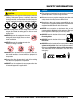
Safety Information Do not operate or service the equipment before reading the entire manual. Safety precautions should be followed at all times when operating this equipment. Failure to read and understand the safety messages and operating instructions could result in injury to yourself and others. Potential hazard associated with the operation of this equipment will be referenced with hazard symbols which may appear throughout this manual in conjunction with safety messages.
Safety Information gENEral SafETy CaUTION NeveR operate this equipment without proper protective clothing, shatterproof glasses, respiratory protection, hearing protection, steel-toed boots and other protective devices required by the job or city and state regulations. Avoid wearing jewelry or loose fitting clothes that may snag on the controls or moving parts as this can cause serious injury. NeveR operate this equipment when not feeling well due to fatigue, illness or when under medication.
Safety Information TrOwEl SafETy NOTICE alwayS keep the machine in proper running condition. daNgEr Engine fuel exhaust gases contain poisonous carbon monoxide. This gas is colorless and odorless, and can cause death if inhaled. The engine of this equipment requires an adequate free flow of cooling air. NeveR operate this equipment in any enclosed or narrow area where free flow of the air is restricted.
Safety Information NOTICE NeveR run engine without an air filter or with a dirty air filter. Severe engine damage may occur. Service air filter frequently to prevent engine malfunction. NeveR tamper with the factory settings of the engine or engine governor. Damage to the engine or equipment can result if operating in speed ranges above the maximum allowable. Store fuel in appropriate containers, in well-ventilated areas and away from sparks and flames. NeveR use fuel as a cleaning agent.
Safety Information eNvIRONmeNTaL SaFeTy/DeCOmmISSIONINg NOTICE emISSIONS INFORmaTION NOTICE Decommissioning is a controlled process used to safely retire a piece of equipment that is no longer serviceable. If the equipment poses an unacceptable and unrepairable safety risk due to wear or damage or is no longer cost effective to maintain (beyond life-cycle reliability) and is to be decommissioned (demolition and dismantlement),be sure to follow rules below.
Trowel SPECIFICATIONS/DIMENSIONS TOP VIEW C B A SIDE VIEW D Figure 1. Dimensions Table 1. Trowel Specifications A–Height (Lifting Bale) – in. (mm) 31.5 (800) B–Height (Handle) – in. (mm) Standard Quick Pitch C–Width (Ring Diameter) – in. (mm) D–Length – in. (mm) 40 (1,016) 40 (1,016) 46.5 (1,181) 74 (1,880) Number of Blades Path Width – in. (mm) Rotor – RPM (Dry Concrete) Gear Box Oil Capacity – oz (ml) Shipping Weight – lbs. (kg) 4 46 (1,168) 60-130 26 (769) Standard Quick Pitch 285 (129.
engine SPECIFICATIONS Table 3. Engine Specifications/Dimensions Model Subaru EX270DE5013 Engine Air-cooled 4 stroke, Slant Single Cylinder, OHC, Type Horizontal PTO Shaft Gasoline Engine Bore X Stroke 2.95 in. X 2.36 in. (75 mm x 60 mm) Displacement 16.17 cu-in. (265 cc) Max. Output 9.0 H.P. @ 4000 RPM Fuel Tank Capacity Approx. 1.59 U.S. Gallons (6.1 Liters) Fuel Unleaded Gasoline Lube Oil Capacity 1.0 qt. (1.
general information Intended Use Operate this trowel, tools and components in accordance with the manufacturer's instructions. Use of any other tools for stated operation is considered contrary to designated use. The risk of such use lies entirely with the user. The manufacturer cannot be held liable for damages as a result of misuse Trowel Familiarization This walk-behind trowel is designed for the floating and finishing of concrete slabs. Take a walk around the trowel.
trowel COMPONENTS 4 5 6 7 8 3 2 16 10 9 QUICK PITCH ™ HANDLE (OPTION) 1 15 14 13 12 11 Figure 2. Trowel Control and Components Figure 2 shows the location of the basic controls or components, for the trowel. Listed below is a brief explanation of each control or component. 1. Access Panel — Allows access to the blade area. NEVER run the trowel with this access panel removed. 2. Engine — Subaru 9.0 HP gasoline engine. 3.
engine COMPONENTS Figure 3. Engine Components and Controls INITIAL SERVICING The engine (Figure 3) must be checked for proper lubrication and filled with fuel prior to operation. Refer to the manufacturer's engine manual for instructions and details of operation and servicing. 1. Muffler – Used to reduce noise and emissions. NEVER touch when hot! 2. Air Cleaner – Prevents dirt and other debris from entering the fuel system. Remove wing-nut on top of air filter canister to gain access to filter element.
assembly and installation Assembly and Installation NOTICE Before the trowel can be put into operation there are some components that must be installed before the trowel can be used. This section provides general instructions on how to install those components. Instruction sheet P/N 20485 provides further details for the handle assembly. Handle Tube Installation 13. Attach the main handle (tube) to the gearbox as shown in (Figure 4). The mounting hardware should be contained in the shipping container.
assembly and installation 7. Adjustment of the throttle cable tension may be required. If so, loosen the adjusting nut (top nut) on the throttle cable receiver (Figure 7) and loosen or tighten the locking nut (bottom nut). Retighten adjusting nut. ADJUSTING NUT (TOP) LOCKING NUT (BOTTOM) 2. For Quick Pitch™ Handle models expose the pitch cable to maximum by grasping the T-handle (Figure 10), then squeezing the trigger lock and pushing the T-handle forward for no pitch (blades flat).
inspection 4. Align the groove on the slider with the text "B" FINISH or "B" COMBO on the decal. The letter "B" stands for B-46 Walk-Behind Trowel BLADE PITCH CABLE CAUTION ALWAYS wear approved eye and hearing protection before operating the trowel. YOKE YOKE EYELET BRASS SET NUT #1 BRASS SET NUT #2 Figure 12. Pitch Cable Yoke Attachment 6. Using a wrench, tighten the brass set #2 nut up against the yoke boss. This will lock the cable in place. 7.
inspection 3. Insert and remove the dipstick without screwing it into the filler neck. Check the oil level shown on the dipstick. 4. If the oil level is low (Figure 15), fill to the edge of the oil filler hole with the recommended oil type as listed in Table 4. Reference Table 3 for maximum engine oil capacity. Gearbox Oil 1. Determine if the gearbox oil is low by removing the oil plug located on the side of the gearbox. (Figure 16) This plug will be marked by the "check" decal.
inspection/operation Centrifugal Safety "STOP" Switch This trowel has been equipped with a centrifugal safety "STOP" switch (Figure 17). This switch should be tested every time the engine is started. The switching mechanism of this switch should operate freely and should always be kept in this condition. With the switch in the OFF position, the engine should not start or run. The purpose of this switch is to stop the engine in a runaway situation, (i.e. the operator releasing the handle during operation).
operation NEVER lift the trowel to unnecessary heights. DO NOT stand underneath the trowel while it is being lifted. Serious damage to the machine or personal injury could be caused by dropping a trowel. 3. Place the centrifugal safety "STOP" switch (Figure 21) in the "ON" position. Starting the Engine OFF 1. Place the engine fuel valve lever (Figure 19) in the "ON" position. ON OFF CENTRIFUGAL SAFETY “STOP” SWITCH Figure 21. Centrifugal Safety"Stop" Switch (ON) ON Figure 19.
operation 5. If starting a warm engine place the choke lever (Figure 23) in the "OPEN " position. 8. Before the trowel is placed into operation, run the engine for several minutes. Check for fuel leaks, and noises that would associate with a loose guard ring and/or covers. Testing the Centrifugal Safety Stop Switch 1. With the engine running at idle, place the safety stop switch lever in the "OFF" position (Figure 26). Verify that the engine shuts off.
operation To Begin Troweling Pitching the Blades (Quick Pitch™ Handle) 1. To begin troweling, push the throttle lever (Figure 28) forward To pitch the blades upwards using the "Quick Pitch™" handle, (Figure 30) simply pull the T-handle backwards while squeezing the trigger. Pushing the T-handle forward will cause the blades to lay flat. to the "RUN" position. RUN T-HANDLE THROTTLE LEVER TRIGGER (SQUEEZE) NO PITCH (BLADES FLAT) Figure 28.
operation Maneuvering the Trowel 1. Get into the operator’s position behind the handle. With a secure foothold and a firm grasp on the handle, slowly increase the engine speed until the desired blade speed is obtained. 2. Figure 31 below illustrates a typical walk-behind trowel application. Practice maneuvering the trowel. The trick is to let the trowel do the work. 3. Continue to practice maneuvering the trowel. Try to practice as if you were finishing a slab of concrete.
operation Stopping The Engine 1. Move the throttle lever to the (Figure 32) "IDLE" position and run the engine for three minutes at low speed. 4. Close the fuel shut- off valve (Figure 35) by moving the fuel valve lever to the OFF position. OFF IDLE THROTTLE LEVER Figure 35. Fuel Valve Lever (OFF) Figure 32. Throttle Lever (Idle) 2. After the engine cools, turn the engine start/stop switch to the “OFF” position (Figure 33). Figure 33. Engine ON/OFF Switch (OFF Position) 3.
options Clip-On Float Blades (Optional) NOTICE Trowel blades should be changed when they fail to finish concrete in a satisfactory manner. Blades are a vital part of finishing concrete. This trowel, or finisher, has been designed to finish concrete and the blades are built to stringent quality standards out of the finest steel.
options Trowel Arm Adjustment Tool (Optional) If blades show uneven wear patterns or some tend to wear out faster than others, the trowel arms may need to be adjusted. A special tool is available (Figure 40) that will adjust all of the trowel arms consistently. The Trowel Arm Fixture P/N is 1817. Figure 40. Trowel Arm Adjustment Fixture Quick Pitch™ Handle (Optional) This feature (Figure 41) is not standard equipment on this model walk-behind trowel. To order this feature please contact MQ unit sales.
maintenance Table 5. Engine Maintenance Schedule EVERY EVERY 6 FIRST BEFORE YEAR MONTHS DESCRIPTION MONTH OR OPERATION EACH OR 300 OR 100 (3) 20 HRS. USE HRS. HRS. Check X Engine Oil Change X X Engine Oil Filter Replace Every 200 Hrs. Check X Air Cleaner Clean X (1) Change Spark Plugs Spark Arrester Fuel Filter Fuel Tube Check/Adjust EVERY 2 YEARS OR 500 HRS. X (*) X Replace Clean Replace Check X X X (2) Every 2 years (replace if necessary) (2) * - Replace the paper filter element only.
maintenance General maintenance practices are crucial to the performance and longevity of your trowel. This equipment requires routine cleaning, blade and trowel arm inspection, lubrication and V-belt inspection for wear and damage. Reference Table 5 and Table 6 for scheduled engine and trowel maintenance.
maintenance NOTICE GAP Operating the engine with loose or damaged air cleaner components could allow unfiltered air into the engine causing premature wear and failure. .028 - .031 IN. (0.7- 0.8 MM.) Engine oil 1. Drain the engine oil when the oil is warm as shown in Figure 43. Figure 44. Spark Plug Gap 2. Remove the oil drain bolt and sealing washer and allow the oil to drain into a suitable container. V-belt 3. Replace engine oil with recommended type oil as listed in Table 4.
maintenance spark arrester cleaning Blade Pitch Adjustment Procedure Clean the spark arrester every 6 months or 100 hours. The maintenance adjustment of blade pitch is an adjustment that is made by a bolt (Figure 48) on the arm of the trowel arm lever. This bolt is the contact point of the trowel arm lever to the lower wear plate on the thrust collar. The goal of the adjustment is to promote consistent blade pitch and finishing quality.
maintenance 2. Pitch the blades as flat as possible. The pitch adjustment bolts (Figure 49) should all barely make contact (0.10 inch max. clearance) with the lower wear plate on the spider. All pitch alignment bolts should be spaced the same distance from the lower wear plate. If one is not making contact, adjustment will be necessary.
maintenance changing blades Trowel arm removal It is recommended that ALL the blades on the trowel are changed at the same time. If only one or some of the blades are changed, the machine will not finish concrete consistently and the machine may wobble or bounce. 1. Each trowel arm is held in place at the spider plate by a hex head bolt (zerk grease fitting) and a roll pin. Remove both the hex head bolt and the roll pin (Figure 53) from the spider plate.
maintenance checking trowel arm straightness trowel arm Lever adjustment Trowel arms (Figure 54) can be damaged by rough handling, such as dropping the trowel on the pad, or by striking exposed plumbing, forms, or rebar while in operation. A bent trowel arm will not allow the trowel to operate in a smooth fluid rotation. If bent trowel arms are suspect, check for flatness as follows: The easiest and most consistent way to adjust the trowel arm lever is to use the Trowel Arm Adjustment Fixture (P.N.
maintenance 7. Once the correct adjustment is made, tighten the lock nut on the trowel arm to lock in place. 8. Loosen locking nuts on the adjustment fixture, and remove trowel arm. 9. Repeat steps for the remaining trowel arms. ReAssembly 1. Clean and examine the upper/lower wear plates and thrust collar. Examine the entire spider assembly. Wire brush any concrete or rust buildup. If any of the spider components are found to be damaged or out of round, replace them. 2.
maintenance LONG-TERM STORAGE For storage of the trowel for over 30 days, the following is required: Drain the fuel tank completely, or add STA-BIL to the fuel. Run the engine until the gasoline in the carburetor is completely consumed. Completely drain the oil from the crankcase and refill with fresh oil. Remove the spark plug. Pour 5 to 10 cc of SAE 30 oil into the cylinder. Turn the engine switch to the START position for a few seconds to distribute the oil. Reinstall the spark plug.
troubleshooting Troubleshooting (engine) Symptom possible problem Spark plug bridging? Check gap, insulation or replace spark plug. Carbon deposit on spark plug? Clean or replace spark plug. Short circuit due to deficient spark plug insulation? Check spark plug insulation, replace if worn. Improper spark plug gap? Set to proper gap. Fuel reaching carburetor? Check fuel line. Water in fuel tank? Flush or replace fuel tank. Fuel filter clogged? Replace fuel filter.
troubleshooting Troubleshooting (engine) - continued Symptom Weak in power, compression is proper and does not misfire. Weak in power, compression is proper but misfires. Engine overheats. Rotational speed fluctuates. Recoil starter malfunctions. (if applicable) Starter malfunctions. possible problem Air cleaner dirty? Clean or replace air cleaner. Improper level in carburetor? Check float adjustment, rebuild carburetor. Defective spark plug? Clean or replace spark plug.
troubleshooting Troubleshooting (Walk-behind Trowel) Symptom possible problem Solution Engine ON/OFF Switch in "OFF" position Make sure that the Engine ON/OFF Switch is ON or malfunctioning? or replace switch if necessary. Engine running rough or not at all. Centrifugal ON/OFF Switch in "OFF" position or malfunctioning? Place centrifugal stop switch in "ON" position. Check wiring. Replace switch if necessary. Fuel? Look at the fuel system. Make sure there is fuel being supplied to the engine.
troubleshooting Troubleshooting (Walk-behind Trowel) - continued Symptom Machine has a perceptible rolling motion while running. Clutch slipping or sluggish response to engine speed change. Trowel blades do not rotate. possible problem Solution Main shaft? The main output shaft of the gearbox assembly should be checked for straightness. The main shaft must run straight and cannot be more than 0.003"" (0.08 mm) out of round at the spider attachment point.
WIRING DIAGRAM ON OF F CENTRIFUGAL STOP SWITCH YEL BLK YEL OIL LEVEL SWITCH BLK OIL ALERT UNIT BLK ENGINE STOP SWITCH UNIT IGNITION COIL GRN TRANSISTORIZED IGNITION UNIT OIL LEVEL INDICATOR CHASSIS GND. page 42 — b46S90 WALK-BEHIND TROWEL • operation and parts manUAL — rev.
notes b46s90 WALK-BEHIND TROWEL • operatION And parts manual — rev.
Explanation of Code in Remarks Column The following section explains the different symbols and remarks used in the Parts section of this manual. Use the help numbers found on the back page of the manual if there are any questions. NOTICE The contents and part numbers listed in the parts section are subject to change without notice. Multiquip does not guarantee the availability of the parts listed. SampLe paRTS LIST NO. 1 2% 2% 3 4 paRT NO. paRT Name QTy. RemaRKS 12345 BOLT .....................1 .....
Suggested Spare Parts B46S90 WALK-BEHIND TROWEL with subaru ex270de5013 gasoline engine 1 to 3 Units Qty. P/N Description 2............20478.....................GRIP, HANDLE 1............21046.....................GASKET/SEAL KIT 1............21047.....................BEARING KIT 1............20285.....................PITCH CABLE (STD) 1............20297.....................PITCH CABLE (QP) 1............21172.....................THROTTLE CABLE 1............10968.....................THRUST BEARING KIT 1.....
NAMEPLATE AND DECALS STANDARD HANDLE 3 2 5 4 QUICK PITCH™ HANDLE 6 P/N 23700 P/N 36099 1 7 PRELOAD TRIM INDICATOR FINISH J COMBO B FINISH COMBO 11 P/N 36099 MODEL SERIAL NO. 10 9 8 P/N 23700 12 WALK-BEHIND POWER TROWEL WWW.MULTIQUIP.COM WALK-BEHIND POWER TROWEL WWW.MULTIQUIP.COM page 46 — b46S90 WALK-BEHIND TROWEL • operation and parts manUAL — rev.
NAMEPLATE AND DECALS NO. PART NO. 1# 23698 2# 23699 3# 23700 4# 36099 5# 23701 6 23702 7# 20816 8 9# 23703 10# 23704 11 1735 12 22897 PART NAME QTY. REMARKS ISO DECAL, ROTATING BLADE HAZARD, 2.00” DIA. 1 ISO DECAL, READ MANUAL, 2.00” DIA. 1 ISO DECAL, LIFTING/CRUSH, 2.4” X 2.0” 1 ISO DECAL, PROTECTIVE CLOTHING, 3.50” X 1.13” 1 ISO DECAL, ASK FOR TRAINING, 2.00” DIA. 1 DECAL, MQ LOGO 12.30” X 1.457” 1 DECAL, MQ LOGO 6.78” X .80” 1 DECAL, SERIAL PLATE, WBT........................................1..........
STANDARD HANDLE ASSY. 26 27 14 28 33 30 23 29 20 31 NS IO 10 CT RU ST IN 1 2 12 17 9 6 37 15 32 22 25 11 24 21 13 16 5 4 7 19 35 3 18 34 36 8 page 48 — b46S90 WALK-BEHIND TROWEL • operation and parts manUAL — rev.
STANDARD HANDLE ASSY. NO. 1# 2# 3# 4# 5# 6# 7# 8# 9# 10# 11# 12# 13# 14# 15# 16# 17#% 18#% 19#% 20# 21# 22# 23# 24# 25# 26# 27#@ 28#@ 29#@ 30#@ 31#@ 32# 33#@ 34#$ 35#$ 36#$ 37 PART NO. 0786 0786 A 1116 1665 3233 9154 10133 20280 20285 20287 20439 20478 20514 20819 20856 21017 22732 21172 21173 22055 22059 22095 22166 22167 22206 22100 20817 0281 3615 0122 c 1478 21243 20282 A1118 20279 20275 22094 PART NAME QTY.
quick-pitch HANDLE ASSY. (option) 18 47 38 36 37 35 6 39 7 34 40 17 IN ST RU C T IO 41 42 NS 43 44 31 12 45 20 24 28 51 2 3 32 13 22 27 33 4 15 14 19 8 5 48 50 16 49 21 29 11 26 30 25 46 1 10 9 23 page 50 — b46S90 WALK-BEHIND TROWEL • operation and parts manUAL — rev.
quick-pitch HANDLE ASSY. (option) NO. 1# 2# 3# 4# 5# 6#$ 7#$ 8# 9# 10# 11# 12# 13# 14# 15# 16# 17# 18# 19# 20# 21# 22# 23# 24#% 25#% 26#% 27# 28# 29# 30# 31# 32# 33# 34#$ 35# 36#$ 37#$ 38#$ 39#$ 40#$ 41#@ 42#@ 43#@ 44#@ 45#@ 46# 47#$ 48#& 49#& 50 51 PART NO.
GUARD RING ASSY. 13 4 1 BLUE LOCTITE 5 3 1 7 2 8 6 E BLU ITE T LOC 13 9 10 1 12 1 11 NOTES: APPLY BLUE LOCTITE™ 246, ITEM 13. page 52 — b46S90 WALK-BEHIND TROWEL • operation and parts manUAL — rev.
GUARD RING ASSY. NO. 1 2 3 4 5 6 7 8 9 10 11 12 13 PART NO. 21973 0205 1391 10024 21894 21979 26250 21893 21986 21922 933241 13351 60097 PART NAME GUARD RING SCREW, HHC 3/8-16 X 1.0 SCREW, HHC 5/16-24 X 1-1/2 ZINC NUT, NYLOC 1/4-20 CLIP, FAST LEAD ACCESS PANEL, B FINISHER SCREW, HHC 1/4 - 20 X 1-3/4 SCREW, FAST LEAD WASHER,FAST LEAD-STAINLESS CLAMP, 0.625" ID PIPE WASHER, FLAT SAE 5/16 GRD 9YZ WASHER, FLAT 3/8 EXT THICK HIGH LOCTITE ™ #246, BLUE QTY.
gearbox ASSY. 12 7 2 1 1 3 31 6 8 4 9 4 6 7 7 9 30 GEARBOX OIL 22 OZ. (751 mL) 11 6 8 13 14 2 10 33 15 17 16 34 18 32 19 35 13 8 20 19 NOTES: 1 APPLY THREAD LOCK, LOCTITE 246 BLUE P/N 60097 OR EQUIVALENT. 2 APPLY THREAD LOCK, LOCTITE 572 WHITE P/N 60096 OR EQUIVALENT. 3 TORQUE TO 15 FT-LBS (20 Nm) 4 GASKETS ARE NOT SOLD SEPARATELY. SHIM (GASKETS) AS NECESSARY FOR INPUT SHAFT END-PLAY. 5 GASKETS ARE NOT SOLD SEPARATELY. SHIM (GASKETS) AS NECESSARY FOR OUTPUT SHAFT END-PLAY.
gearbox ASSY. NO. 1%$ 2% 3% 4%$ 6%# 7%# 8% 9% 10% 11% 12 13 14% 15% 16% 17% 18%# 19%# 20% 21% 22% 23% 25%$ 26% 27% 28% 29%$ 30 31 32 33 34 35 PART NO. 0753 0131 A 12876 20395 20466 20465 0627 1851 12874 21218 21046 21047 20476 21033 0121 A 1138 20475 20474 1140 20470 1139 1238 20396 12875 10235 20875 0254 20407 10139 22292 20802 1150 20801 PART NAME QTY.
ENGINE ASSY. 20 1 8 19 2 18 17 5 16 21 15 1 3 22 14 13 28 1 6 23 BLUE LOCTITE 23 4 25 BLUE LOCTITE BLUE LOCTITE 23 29 4 4 1 9 10 1 11 30 NOTES: 1 APPLY BLUE LOCTITE™ 246, ITEM 23. 12 page 56 — b46S90 WALK-BEHIND TROWEL • operation and parts manUAL — rev.
ENGINE ASSY. NO. 1 2 3 4 5 6 8 9 10 11 12 13@ 14@ 15@ 16@ 17@ 18@ 19@ 20 21 22 23 25 26 27 28 29 30 PART NO. 22996 1475 1488 12287 21984 933241 0250 0627 21140 0152 3 21970 0253 1868 0855 B1766 0251 0456 0252 20845 1834 1273 60097 1406 21915 21679 10229 21678 0300 B PART NAME QTY. REMARKS ENGINE, SUBARU 9.0 HP, EX27 1 CONNECTOR, SPLICE TAP 1 WIRE, SAFETY SWITCH 1 SCREW, THP 1/4- 20 X 3/4 SS 3 LIFTING BALE ASSEMBLY B FIN 1 WASHER, FLAT SAE 5/16 RD 9 YZ 4 CLUTCH ASSEMBLY 1" CENTRIFUGAL,..........1..........
spider ASSY. 17 18 25 16 19 20 3 21 15 2 1 1 11 14 1 4 13 2 7 9 22 5 10 6 23 4 5 3 12 8 NOTES: 1 APPLY LOCTITE P/N 1477 TO ITEMS 1 AND 14 SPIDER ASSEMBLY P/N 1490 2 INCLUDES ALL ITEMS WITHIN OUTLINE. 3 INCLUDED WITH ITEM 19 OR CAN BE ORDERED SEPARATELY (P/N 1471) 4 TORQUE TO 90 FT.-LBS (122 Nm) 24 5 TORQUE TO 130 FT.-LBS (176 Nm) page 58 — b46S90 WALK-BEHIND TROWEL • operation and parts manUAL — rev.
spider ASSY. NO. 1% 2% 3% 4% 5% 6% 7% 8% 9% 10% 11% 12% 13% 14% 15 16 17$ 18$ 19$ 20$# 21$ 22 24 25 PART NO. 0164 B 0166 A 1157 A 1161-1 1162 A 1163-1 1316 1322 1456 1875 1876 2827-1 4164 12097 1490 10968 12208 12778 10793 1471 1154 A 21906 C464 1817 PART NAME QTY. REMARKS RADIUS HEAD 3/8-16, FULL THREAD 4 LOCK WASHER 3/8 MED 4 BUSHING, TROWEL ARM 4 SPIDER PLATE 1 CAP, GREASE ZERK #2 YELLOW 4 LEVER, TROWEL ARM RIGHT HAND 4 SPRING, LS ARM RETURN 4 RETAINING SCREW ASSY.
stabilizer ring ASSY. SEE DETAIL “A” 6 DETAIL “A” 4 4 3 1 5 2 BLUE LOCTITE 1 1 1 APPLY LOCTITE 242 BLUE OR EQUIVALENT. page 60 — b46S90 WALK-BEHIND TROWEL • operation and parts manUAL — rev.
stabilizer ring ASSY. NO. 1 2 3 4 5 6 PART NO. 1237 1477 1723 6014 C 0300 B 1483 PART NAME SCREW, SCH 5/16-18 X 7/8, NYL, NP LOCTITE, 242 ROD END, 5/16-24 MALE NUT, HEX FINISH 5/16-24 WASHER, FLAT SAE 5/16" RING, STABILIZER, 16-1/2" ARM QTY. 4 ` 4 8 4 1 REMARKS b46s90 WALK-BEHIND TROWEL • operatION And parts manual — rev.
BLADE ASSY. 2 1 8 15 14 16 17 11 13 9 12 10 5 5 6 page 62 — b46S90 WALK-BEHIND TROWEL • operation and parts manUAL — rev.
BLADE ASSY. NO. PART NO. 1 C464 2 21906 3 4 5 6 7 8 9 9 10 10 11 11 12 12 13 0201 14 15 16 1434 17 0202 PART NAME QTY. REMARKS TROWEL BLADE, 8 X 18 STANDARD BC 4 SCREW, HHFS 5/16 - 18 X 1-1/2 GR5 8 BLADE AND PAN ACCESSORIES, ALL............1................SEE NOTICE BELOW REVERSIBLE COMBO BLADE..........................4................SEE NOTICE BELOW FLOAT DISC LATCH PIN....................................4................SEE NOTICE BELOW TROWEL ARM ADJ. FIXTURE ASM......
eX27 — crankcase assy. page 64 — b46S90 WALK-BEHIND TROWEL • operation and parts manUAL — rev.
eX27 — crankcase assy. NO. PART NO. 10 2791010611 20# 2371420203 26# 2771601001 30$ 0440300160 40$ 0600300370 50$ 2771501103 60# 0105080250 70# 0105060410 75$ 0440060020 80 0401140030 90@ 0211140020 210 2791100221 220% 0440300160 230% 0600300370 250 27745004K1 260 2774190203 270 2796360113 280@ 0213200050 300 0010408350 610 2791300121 620@ 2791500133 630 0110080240 631 0110080310 680 2771550301 690@ 2771600113 700 2771501103 710 0110060020 960 2799900127 PART NAME QTY. REMARKS CRANK CASE CP ............
EX27 — crankshaft assy. page 66 — b46S90 WALK-BEHIND TROWEL • operation and parts manUAL — rev.
EX27 — crankshaft assy. NO. 10 50 70 80 310 320# 350 360 370 380 PART NO. 2792090161 0180180010 0323030010 2072600103 2792250120 2792300103 2792330113 27923401H3 2792351117 0565180010 PART NAME QTY. REMARKS CRANK SHAFT CP 1 FLANGE NUT 1 WOODRUFF KEY 1 KEY 1 CONNECTING ROD ASSY.................................1................INCLUDES ITEMS W/# CONNECTING ROD BOLT 2 PISTON PIN 1 PISTON 1 PISTON RING SET 1 CLIP 2 b46s90 WALK-BEHIND TROWEL • operatION And parts manual — rev.
EX27 — muffler assy. page 68 — b46S90 WALK-BEHIND TROWEL • operation and parts manUAL — rev.
EX27 — muffler assy. NO. 10 25 27 34% 35% 37% 38% 60 70 80 90 95 150 160 163 166 170 200 202+ 220 225 230# 231@ 240# 241@ 290 310 315 317 320 340 350 360 361 365 387 440 540 560$ 570 580 PART NO.
EX27 — air cleaner assy. page 70 — b46S90 WALK-BEHIND TROWEL • operation and parts manUAL — rev.
EX27 — air cleaner assy. NO. 510 510-210# 510-220# 510-250# 510-260# 510-270# 510-520# 570 580 PART NO. 2793261570 2793272008 2793265018 2793264318 2793273008 2793274008 2793260618 0023806000 0010406200 PART NAME QTY. REMARKS AIR CLEANER ASSY...........................1................INCLUDES ITEMS W/# PACKING 1 GASKET 1 COVER 1 LABEL 1 WING NUT 2 ELEMENT SET 1 FLANGE NUT 2 FLANGE BOLT 1 b46s90 WALK-BEHIND TROWEL • operatION And parts manual — rev.
EX27 — governor assy. page 72 — b46S90 WALK-BEHIND TROWEL • operation and parts manUAL — rev.
EX27 — governor assy. NO. 10 20 30 40 50 60 70 80 310 322 340 350 355 360 365 395 396 435 440 450 480 485 PART NO. 2794230153 2774220133 2794270111 2774280123 0031305000 0011406250 0186060020 2794250273 2774330301 2774370101 2774350203 2774450103 0217060070 0043106250 2374500423 2774390203 0131050030 2774600201 0043104080 0023506000 2774510303 0110060020 PART NAME GOVERNOR LEVER GOVERNOR SHAFT GOVERNOR ROD CP ROD SPRING CLIP BOLT AND WASHER AY NUT GOVERNOR SPRING SPEED CONT.
EX27 — blower assy. page 74 — b46S90 WALK-BEHIND TROWEL • operation and parts manUAL — rev.
EX27 — blower assy. NO. 10 20 40 60 61 80 81 220 PART NO. 2795120201 0732005820 0110060030 2795271111 2795270213 20A0111500 0110060020 0130060281 PART NAME BLOWER HOUSING CP LABEL (TRADE MARK) FLANGE BOLT BAFFLE 1 (CASE) CP BAFFLE 2 (HEAD) FLANGE BOLT FLANGE BOLT FLANGE BOLT QTY. 1 1 4 1 1 1 1 4 REMARKS b46s90 WALK-BEHIND TROWEL • operatION And parts manual — rev.
EX27 — RECOIL STARTER assy. page 76 — b46S90 WALK-BEHIND TROWEL • operation and parts manUAL — rev.
EX27 — RECOIL STARTER assy. NO. 210 210-1# 210-2# 210-3# 210-4# 210-5# 210-6# 210-8# 210-11# 210-49# PART NO. 2795030120 2265071608 2775012108 2795011008 2265070118 2815032508 2815033008 2265074108 2795014508 2815035108 PART NAME QTY. REMARKS RECOIL STARTER AY ...............................1................
EX27 — fuel tank assy. page 78 — b46S90 WALK-BEHIND TROWEL • operation and parts manUAL — rev.
EX27 — fuel tank assy. NO. 10 20 23 30 40 48 60 63 70 80 90$ PART NO. 2796010211 0732005181 2799511203 X430440161 X641360010 0505120020 0023808000 0110080250 2796260201 X851061580 0561110050 PART NAME QTY. REMARKS FUEL TANK CP 1 LABEL (WARNING) 1 LABEL (MODEL) 1 FUEL TANK CAP CP 1 FUEL FILTER 1 UNION 1 FLANGE NUT 2 FLANGE BOLT 2 FUEL PIPE CP ...................................................1................
EX27 — carburetor assy. page 80 — b46S90 WALK-BEHIND TROWEL • operation and parts manUAL — rev.
EX27 — carburetor assy. NO. 210 210-1# 210-2# 210-3# 210-5# 210-8# 210-11# 210-12# 210-14# 210-15# 210-16# 210-17# 210-18# 210-19# 210-22# 210-28# 210-40# 210-41# 210-79# 210-102# 210-103# 210-151# 210-152# 210-300# 210-302#$ 210-303#$ 210-325# 210-327# 224 PART NO.
EX27 — ignition coil assy. page 82 — b46S90 WALK-BEHIND TROWEL • operation and parts manUAL — rev.
EX27 — IGNITION COIL assy. NO. 10 11 30 50 100 110 705 741 780 PART NO. 2797923101 2797943001 0010406200 27773101H1 0650140150 0655000270 KU31107101 0110060010 0569000020 PART NAME FLYWHEEL CP IGNITION COIL CP BOLT AND WASHER AY WIRE 1 CP SPARK PLUG SPARK PLUG CAP FLOAT C/U CP3 FLANGE BOLT PURSE LOCK QTY. 1 1 2 1 1 1 1 1 1 REMARKS b46s90 WALK-BEHIND TROWEL • operatION And parts manual — rev.
EX27 — oil sensor assy. page 84 — b46S90 WALK-BEHIND TROWEL • operation and parts manUAL — rev.
EX27 — oil sensor assy. NO. 700 740 770 775 780 PART NO. 2797630151 0010406140 2797550123 0152060050 0569000020 PART NAME OIL SENSOR CP BOLT AND WASHER AY WIRE CLAMP TAPPING BOLT PURSE LOCK QTY. 1 2 1 1 1 REMARKS b46s90 WALK-BEHIND TROWEL • operatION And parts manual — rev.
Terms and Conditions of Sale — Parts paymeNT TeRmS 5. Parts must be in new and resalable condition, in the original Multiquip package (if any), and with Multiquip part numbers clearly marked. 6. The following items are not returnable: Multiquip reserves the right to quote and sell direct to Government agencies, and to Original Equipment Manufacturer accounts who use our products as integral parts of their own products. a. SpeCIaL eXpeDITINg SeRvICe Terms of payment for parts are net 30 days.
notes b46s90 WALK-BEHIND TROWEL • operatION And parts manual — rev.
Operation and Parts Manual HERE’S HOW TO GET HELP PLEASE HAVE THE MODEL AND SERIAL NUMBER ON-HAND WHEN CALLING United StateS Multiquip Corporate Office 18910 Wilmington Ave. Carson, CA 90746 Contact: mq@multiquip.com MQ Parts Department Tel.