OPERATION AND PARTS MANUAL SERIES MODEL MVH-306DS2 REVERSIBLE PLATE COMPACTOR (YANMAR L70V6GJ1R1AAS5 DIESEL ENGINE) Revision #2 (08/15/07) To find the latest revision of this publication, visit our website at: www.multiquip.com THIS MANUAL MUST ACCOMPANY THE EQUIPMENT AT ALL TIMES.
MVH-306DS2 PLATE COMPACTOR — PROPOSITION 65 WARNING PAGE 2 — MVH-306DS2 PLATE COMPACTOR — OPERATION AND PARTS MANUAL — REV.
NOTES MVH-306DS2 PLATE COMPACTOR — OPERATION AND PARTS MANUAL — REV.
TABLE OF CONTENTS MIKASA MVH-306DS2 REVERSIBLE PLATE COMPACTOR Proposition 65 Warning ..............................................2 Table Of Contents ......................................................4 Parts Ordering Procedures ........................................5 Safety Message Alert Symbols .............................. 6-7 Rules for Safe Operation ....................................... 8-9 Operation and Safety Decals ...................................10 Specifications ......................
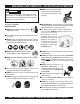
MVH-306DS2 PLATE COMPACTOR — SAFETY MESSAGE ALERT SYMBOLS FOR YOUR SAFETY AND THE SAFETY OF OTHERS! Safety precautions should be followed at all times when operating this equipment. Failure to read and understand the Safety Messages and Operating Instructions could result in injury to yourself and others. This Owner's Manual has been developed to provide complete instructions for the safe and efficient operation of the Multiquip Model MVH-306DS2 Reversible Plate Compactor.
MVH-306DS2 PLATE COMPACTOR — SAFETY MESSAGE ALERT SYMBOLS CAUTION - Rotating Parts CAUTION - Equipment Damage Messages NEVER operate equipment with covers, or guards removed. Keep fingers, hands, hair and clothing away from all moving parts to prevent injury. Other important messages are provided throughout this manual to help prevent damage to your compactor, other property, or the surrounding environment.
MVH-306DS2 PLATE COMPACTOR — RULES FOR SAFE OPERATION DANGER Failure to follow instructions in this manual may lead to serious injury or even death! This equipment is to be operated by trained and qualified personnel only! This equipment is for industrial use only. The following safety guidelines should always be used when operating the compactor: GENERAL SAFETY ■ DO NOT operate or service this equipment before reading this entire manual.
MVH-306DS2 PLATE COMPACTOR — RULES FOR SAFE OPERATION Loading and Unloading (Crane): ■ Before lifting, make sure that machine parts (hook and vibration insulator) are not damaged and screws are not loosened or lost. ■ Always make sure crane or lifting device has been properly secured to the hook of guard frame on compactor. ■ NEVER lift the machine while the engine is running. ■ Use adequate lifting cable (wire or rope) of sufficient strength. ■ Use one point suspension hook and lift straight upwards.
MVH-306DS2 — OPERATION AND SAFETY DECALS Figure 2 displays the operation and safety decals as they appear on the reversible plate compactor. Should any of these decals become damaged or unreadable, contact the Multiquip Parts Department for a replacement set. Figure 2. Operation and Safety Decals PAGE 10 — MVH-306DS2 PLATE COMPACTOR — OPERATION AND PARTS MANUAL — REV.
MVH-306DS2 —SPECIFICATIONS Table 1. MVH-306DS2 Reversible Plate Compactor Specifications Centrifugal Force 10,125 lbs. (4,593 kg) Vibration Frequency 4,400 vpm (70 Hz) Traveling Speed 0 to 75 ft/min (0 to 23 m/min) Plate Size (L x W) 18 x 34 in (45.72 x 86.36 cm) External Plate Size (L x W) 24 x 34 in (60.96 x 86.36 cm) Max. Area of Compaction (no extensions) 6,750 sq. ft. (2,057 sq. meters) Overall Length 61.8 in (1570 mm) Overall Width 18.0 in (457 mm ) Overall Height (with handle) 44.
MVH-306DS2 — DIMENSIONS Figure 3. MVH-306DS2 Reversible Plate Compactor Dimensions TABLE 3. DIMENSIONS REF. DIMENSIONS A 53 in. (134.6 cm.) B 18 in. (46 cm.) C 34 in. (86 cm.) D 63.8 in. (162 cm.) E 32.5 in. (82.5 cm.) PAGE 12 — MVH-306DS2 PLATE COMPACTOR — OPERATION AND PARTS MANUAL — REV.
MVH-306DS2— FEATURES Plate Compactor Frequency/Speed The Mikasa MVH-306DS2 is a walk behind, reversible plate compactor designed for the compaction of sand, clay and asphalt. This plate compactor is a powerful compacting tool capable of applying a tremendous force in consecutive high frequency vibrations to a soil surface. Its applications include soil compacting for road, embankments and reservoirs as well as backfilling for gas pipelines, water pipelines and cable installation work.
MVH-306DS2— PLATE COMPACTOR COMPONENTS Figure 4. MVH-306DS2 Reversible Plate Compactor Components Figure 4 illustrates the location of the major components for the MVH-306DS2 Reversible Plate Compactor. The function of each component is described below: 8. Belt Cover – Remove this cover to gain access to the Vbelts. NEVER run the compactor without the V-belt cover.
MVH-306DS2— ENGINE COMPONENTS Figure 5. MVH-306DS2 Engine Components ENGINE COMPONENTS Figure 5 illustrates the location of the major lever components of the engine. Each component is described below: 6. Recoil Starter– Manual-starting method. Pull the starter grip until resistance is felt, then pull briskly and smoothly. 1. Fuel Filler Cap – Remove this cap to add unleaded gasoline to the fuel tank. Make sure cap is tighten securely. DO NOT over fill. 7.
MVH-306DS2 — PRE-INSPECTION CAUTION NEVER operate the compactor in a confined area or enclosed area structure that does not provide ample free flow of air. 4. If the oil level is low (Figure 7), fill to the edge of the oil filler hole with the recommended oil type (Table 4). Maximum oil capacity is 1.16 quarts (1.10 liters). ALWAYS wear approved eye and hearing protection before operating the compactor. Before Starting 1. 2. 3. Read safety instructions at the beginning of manual. Figure 7.
MVH-306DS2 — PRE-INSPECTION CAUTION DO NOT overfill hydraulic oil tank. This could cause oil leaks and sluggish operation. Clean cap and surrounding area before opening to prevent dirt from entering oil tank. 4. When adding hydraulic oil, only fill to the specified oil level as marked on the front of the hydraulic oil tank (Figure 9). DO NOT overfill Explosive Fuel DANGER Diesel fuel is highly flammable and can be dangerous if mishandled. DO NOT smoke while refueling.
MVH-306DS2 — OPERATION CAUTION DO NOT attempt to operate the compactor until the Safety, General Information and Inspection sections of this manual have been read and thoroughly understood. This section is intended to assist the operator with the initial start-up of the compactor. It is extremely important that this section be read carefully before attempting to use the compactor in the field. Figure 14. Handle Adjustment STARTING THE ENGINE Refer to Figure 3 for the location of controls and components.
MVH-306DS2 — OPERATION 5. If the engine fails to start, DO NOT continue to rotate the ignition key for more than 5 seconds. Return the key to the RUN position and wait 10 seconds before starting again Figure 18. Engine Start Handle 4. Figure 17. Starter Switch (Option) Push down decompression lever (Figure 19) and release. CAUTION While the engine is running, never try to turn the ignition key to the START position. 6.
MVH-306DS2—OPERATION ALWAYS move the throttle lever quickly without hesitation, because increasing the engine speed slowly causes the clutch to slip. 3. To make the compactor move in the forward direction push the travel lever ( Figure 21) forward. Figure 22. Throttle Lever (Stop) Figure 23. Starter Switch (STOP) Figure 21. Travel Lever 4. To make the compactor move in the reverse direction pull the travel lever ( Figure 21) backwards. 5.
MVH-306DS2 — MAINTENANCE CAUTION CAUTION Inspection and other services should always be carried out on hard and level ground with the engine shutdown. Fuel piping and connections should be replaced every 2 years. TABLE 6. MVH-306DS2 ENGINE CHECK Inspection and Maintenance Service Tables. 1. To make sure your plate compactor is always in good working condition before using, carry out the maintenance inspection in accordance with Tables 5 through 7. TABLE 5.
MVH-306DS2 — MAINTENANCE Engine Oil Replacement: 1. Replace engine oil, in first 25 hours of operation and every 50 to 100 hours afterwards. 2. Oil may be drained more easily when it is warm after operation (For more details, see separate engine Owner's Manual). Air Filter (Every 6 Months or 400 Hours) 1. The air filter element should be cleaned because a clogged air cleaner can cause poor engine starting, lack of power and shorten engine life substantially. Figure 25. Engine Air Filter and Element 2.
MVH-306DS2—MAINTENANCE Vibrator Oil Level Check 2. Push the travel lever back and forth to drain the hydraulic oil from the hand pump (hydraulic oil reservoir). CAUTION Always clean the area around the vibrator oil level check plug before removing oil check plug. This will prevent dirt and debris from entering the system. 1. In every 100 hours of operation, with the machine positioned horizontally, use a 3/4” (19 mm) wrench and remove vibrator oil level check plug (Figure 28).
MVH-306DS2 — MAINTENANCE CAUTION Make sure hydraulic oil is at a normal safe operating level. DO NOT over fill. Over filling (excessive oil) will cause excess oil to blow out of bleeder plug. 3. Loosen bleeder plug located at top of hydraulic cylinder on side of vibrator (Figure 32). Air remaining in the circuit will be forced out of the bleeder plug. Once all air has been purged from the hydraulic system, tighten bleeder plug securely 4. Reinsert oil plug into hydraulic oil tank and tighten securely.
MVH-306DS2 — MAINTENANCE z Battery fluid will be lost through continuous charging and LONG TERM STORAGE discharging. When storing your compactor for long periods do the following: z Discontinue charging if the electrolyte temperature exceeds z Run the engine at idle speed for 3-5 minutes. z Stop the engine. Drain the engine crankcase oil while the 117° F (45° C) engine is still warm. Fill Engine crankcase with fresh oil.
MVH-306DS2 —TROUBLESHOOTING Practically all breakdowns can be prevented by proper diagnosis based on the Engine Troubleshooting (Table 8) handling and maintenance inspections, but in the event of a information shown below. If the problem cannot be remedied, please leave the unit just as it is and consult our company's breakdown, please take a remedial action following the business office or service plant. TABLE 8.
MVH-306DS2 —TROUBLESHOOTING Practically all breakdowns can be prevented by proper diagnosis based on the Compactor Troubleshooting (Table 9) handling and maintenance inspections, but in the event of a information shown below. If the problem cannot be remedied, please leave the unit just as it is and consult our company's breakdown, please take a remedial action following the business office or service plant. TABLE 9. TROUBLESHOOTING COMPACTOR SYMPTOM Travel speed low and vibration weak.
MVH-306DS2 — EXPLANATION OF CODES IN REMARKS COLUMN The following section explains the different symbols and remarks used in the Parts section of this manual. Use the help numbers found on the back page of the manual if there are any questions. The contents and part numbers listed in the parts section are subject to change without notice. Multiquip does not guarantee the availibility of the parts listed. * * Numbers Used - Item quantity can be indicated by a number, a blank entry, or A/R.
MVH-306DS2 — SUGGESTED SPARE PARTS MVH-306DS2 W/ YANMAR L70V6 DIESEL ENGINE 1 to 3 Units Qty. ..... P/N ......................... Description 1 ......... 956100054 .............. THROTTLE WIRE 2 ......... 070200373 .............. V-BELT 3 ......... 11425012580 .......... ELEMENT W/ PRE-FILTER 1 ......... 16081076630 .......... STARTER ROPE 2 ......... 11425055121 .......... FUEL FILTER W/GASKET 1 ......... 11428855010 .......... CAP, FUEL TANK W/GASKET 1 ......... 11425035110 ..........
MVH-306DS2 — NAMEPLATE AND DECALS NAMEPLATE AND DECALS PAGE 30 — MVH-306DS2 PLATE COMPACTOR — OPERATION AND PARTS MANUAL — REV.
MVH-306DS2 — NAMEPLATE AND DECALS NAMEPLATE AND DECALS NO. 1 2 3 4 5 6 7 8 9 10 11 12 13 PART NO. 920201950 920105070 920110370 920209620 920207480 920204580 920203330 920211060 920206960 920201580 920211010 920106760 0732004460 PART NAME QTY. REMARKS DECAL: OIL SAE 10W-30 1 DECAL: MIKASA LOGO ............................ 1.........
MVH-306DS2 — VIBRATING PLATE ASSY. VIBRATING PLATE ASSY. PAGE 32 — MVH-306DS2 PLATE COMPACTOR — OPERATION AND PARTS MANUAL — REV.
MVH-306DS2 — VIBRATING PLATE ASSY. VIBRATING PLATE ASSY. NO. PART NO.
MVH-306DS2 — BASE AND ENGINE ASSY. BASE AND ENGINE ASSY. PAGE 34 — MVH-306DS2 PLATE COMPACTOR — OPERATION AND PARTS MANUAL — REV.
MVH-306DS2 — BASE AND ENGINE ASSY. BASE & ENGINE ASSY. NO. PART NO. 1 464117850 2 914410026 3 0105051045 4 030210250 5 031110160 6 464216560 7 011208025 8 030208200 9 031108160 10 464343670 11 464457360 12 456343340 13 951400110 13-1 951406790 14 952400690 15 001220830 16 030208200 17 464216640 18 092006010 19 464343660 20 464216590 21 001521050 35 464117920 36 456449950 37 011208030 38 030208200 39 031108160 40 022710809 PART NAME BASE ENGINE ASSY.
MVH-306DS2 — BASE AND ENGINE ASSY. (CONTINUED) BASE AND ENGINE ASSY. (CONTINUED) PAGE 36 — MVH-306DS2 PLATE COMPACTOR — OPERATION AND PARTS MANUAL — REV.
MVH-306DS2 — BASE AND ENGINE ASSY. (CONTINUED) BASE AND ENGINE ASSY. (CONTINUED) NO. 41 42 43 44 45 46 47 48 49 51 52 53 59 60 61 62 63 64 65 66 70 71 72 103 104 105 106 107 PART NO.
MVH-306DS2 — VIBRATOR ASSY. VIBRATOR ASSY. PAGE 38 — MVH-306DS2 PLATE COMPACTOR — OPERATION AND PARTS MANUAL — REV.
MVH-306DS2 — VIBRATOR ASSY. VIBRATOR ASSY. NO. PART NO.
MVH-306DS2 — CONTROL HANDLE ASSY. CONTROL HANDLE ASSY. PAGE 40 — MVH-306DS2 PLATE COMPACTOR — OPERATION AND PARTS MANUAL — REV.
MVH-306DS2 — CONTROL HANDLE ASSY. CONTROL HANDLE ASSY. NO. PART NO.
MVH-306DS2 — CONTROL HANDLE ASSY. (CONTINUED) CONTROL HANDLE ASSY. PAGE 42 — MVH-306DS2 PLATE COMPACTOR — OPERATION AND PARTS MANUAL — REV.
MVH-306DS2 — CONTROL HANDLE ASSY. (CONTINUED) CONTROL HANDLE ASSY. NO. PART NO.
MVH-306DS2 — HAND PUMP ASSY. HAND PUMP ASSY. PAGE 44 — MVH-306DS2 PLATE COMPACTOR — OPERATION AND PARTS MANUAL — REV.
MVH-306DS2 — HAND PUMP ASSY. HAND PUMP ASSY. NO. B * C * 2 * 3 * 4 * 9 * 10 * 11 * 12 * 13 * 14 * 15 * 16# * 17# * 18# * 19# * 22 * 22 * 26# * 27# * 28# * 50 * 51 * 52# * 53# * 81 * 82 * 83 * 84 PART NO. 4649-10040 464910080 464010040 464010050 464010060 464010070 099205005 464010080 464010090 464010100 458010080 001520620 050200200 050200220 050300380 050200180 464010110 464010111 050300400 050200150 050100400 464010120 458451630 069904010 069901010 984010030 984010040 984010050 464216721 PART NAME QTY.
MVH-306DS2 — BATTERY ASSY. (OPTION) BATTERY ASSY. (OPTION) PAGE 46 — MVH-306DS2 PLATE COMPACTOR — OPERATION AND PARTS MANUAL — REV.
MVH-306DS2 — BATTERY ASSY. (OPTION) BATTERY ASSY. (OPTION) NO. PART NO.
MVH-306DS2 — ELECTRIC DEVICE ASSY. ELECTRIC DEVICE ASSY. 30 2 28 44 1 24 41 41A IG B ST 26 26 PAGE 48 — MVH-306DS2 PLATE COMPACTOR — OPERATION AND PARTS MANUAL — REV.
MVH-306DS2 — ELECTRIC DEVICE ASSY. ELECTRIC DEVICE ASSY. NO. PART NO. 1 464457460 2 464457470 24 464459260 26 454010020 28 955300400 30 506010070 41 955300680 41A# 955000010 44 105198-78570 PART NAME QTY. REMARKS BATTERY CORD (-) 400L 1 BATTERY CORD (+) 550L 1 WIRE CP 1 CLAMP TC-100 3 BUZZER (EBL) 1 CLAMP TC-150 1 IGNITION SWITCH ASSY. ..................................1 ............. INCLUDES ITEMS W/ # IGNITION KEY 1 HARNESS (C), WIRE 1 MVH-306DS2 PLATE COMPACTOR — OPERATION AND PARTS MANUAL — REV.
YANMAR L70V6 ENGINE— CYLINDER BLOCK ASSY. CYLINDER BLOCK ASSY. 47 40 38 42 31 27 52 27 37 35 (50) (51) 11 32 5 25 8 -1 45 30 12 23 24 30 48 29 28 49 43 39 26 44 46 1 42 40 39 43 8 -1 SEE FUEL INJECTION PUMP ASSY. PAGE 50 — MVH-306DS2 PLATE COMPACTOR — OPERATION AND PARTS MANUAL — REV.
YANMAR L70V6 ENGINE — CYLINDER BLOCK ASSY. CYLINDER BLOCK ASSY. NO. 1 5 11 12 23 24 25 26 27 28 29 30 31 32 35$ 37 38 39 40 42# 43 44 45 46 47 48 49 50 51 52 PART NO.
YANMAR L70V6 ENGINE— CYLINDER HEAD ASSY. CYLINDER HEAD ASSY. PAGE 52 — MVH-306DS2 PLATE COMPACTOR — OPERATION AND PARTS MANUAL — REV.
YANMAR L70V6 ENGINE — CYLINDER HEAD ASSY. CYLINDER HEAD ASSY. NO. 1 2 3 7 8 9 10 11 13 14# 15# 16# 18#+ 19#+ 20# 22#$ 23#$ 24 25 26 27 28 29 30 31 32 33 34 35 37 * 40 * 42 * 45 PART NO.
YANMAR L70V6 ENGINE— AIR CLEANER ASSY. AIR CLEANER PAGE 54 — MVH-306DS2 PLATE COMPACTOR — OPERATION AND PARTS MANUAL — REV.
YANMAR L70V6 ENGINE— AIR CLEANER ASSY. AIR CLEANER ASSY. NO. 1 2 * 3 * 4 * 6 * 7 * 10 * 11 12 13 14 PART NO. 11421012510 11421012020 11421012520 11421012560 11421012580 11421012590 11421012600 11429912300 11421012210 26106060202 26226060302 PART NAME QTY. REMARKS AIR CLEANER ASSY. ..................................... 1 ......... INCLUDES ITEMS W/ * AIR CLEANER BODY 1 AIR CLEANER COVER 1 WING NUT 1 STUD BOLT 1 ELEMENT ASSY.
YANMAR L70V6 ENGINE— MUFFLER ASSY. MUFFLER ASSY. PAGE 56 — MVH-306DS2 PLATE COMPACTOR — OPERATION AND PARTS MANUAL — REV.
YANMAR L70V6 ENGINE— MUFFLER ASSY. MUFFLER ASSY. NO. 15 16 22 23 24 25 PART NO. 11429913200 11439913520 26106060142 26216080182 26366080002 11429913800 PART NAME MUFFLER GASKET MUFFLER ASSY. BOLT M 6X14 PLATED STUD M 8X18 PLATED NUT M8 EXHAUST DEFECTOR QTY. 1 1 2 2 2 1 REMARKS MVH-306DS2 PLATE COMPACTOR — OPERATION AND PARTS MANUAL — REV.
YANMAR L70V6 ENGINE— CRANKSHAFT AND CAMSHAFT ASSY. CRANKSHAFT AND CAMSHAFT ASSY. PAGE 58 — MVH-306DS2 PLATE COMPACTOR — OPERATION AND PARTS MANUAL — REV.
YANMAR L70V6 ENGINE— CRANKSHAFT AND CAMSHAFT ASSY. CRANKSHAFT AND CAMSHAFT ASSY. NO. 1 6 7 12 13 21 22 25 * 26 27 45 62 63 64 65 PART NO. 71421014580 11421014200 11421014300 11421014400 71421021740 11428821220 11439921590 11436221600 11429921550 22512040120 71421028510 26106080202 16031014550 22512070360 24101062030 PART NAME QTY. REMARKS CAMSHAFT ASSY. 1 TAPPET 2 ROLLER TAPPET ASSY. 1 PUSH ROD ASSY. 2 CRANKSHAFT (D) ASSY. 1 NUT 1 FLYWHEEL (DE) ASSY. .................................. 1 .........
YANMAR L70V6 ENGINE— PISTON ASSY. PISTON ASSY. PAGE 60 — MVH-306DS2 PLATE COMPACTOR — OPERATION AND PARTS MANUAL — REV.
YANMAR L70V6 ENGINE— PISTON ASSY. PISTON ASSY. NO. 28 28 28 30# 30$ 30% 36 37 38 41 * 42 * 42 42 44 * PART NO. 71421022720 71421022620 71421022580 71487022502 71487022542 71487022552 11439922300 22252000210 71421023700 11820023200 11421023600 11421023610 11421023620 11438023100 PART NAME QTY. REMARKS PISTON W/ RINGS STD ................................. 1 ......... INCLUDES ITEMS W/# PISTON W/RINGS OS=0.25 ........................... 1 ......... INCLUDES ITEMS W/$ PISTON W/RINGS OS=0.50 .................
YANMAR L70V6 ENGINE— LUB. OIL PUMP AND GOVERNOR ASSY. LUB. OIL PUMP & GOVERNOR ASSY. PAGE 62 — MVH-306DS2 PLATE COMPACTOR — OPERATION AND PARTS MANUAL — REV.
YANMAR L70V6 ENGINE— LUB. OIL PUMP AND GOVERNOR ASSY. LUB. OIL PUMP AND GOVERNOR ASSY. NO. 1 7 8 9 10 11 13 * 14 15 27# 32# 35 36+ 41 42 43 44 45 46 47 48 49 50 51 52 54 55 56 57 58 59 60 61 62 63 65% 66% PART NO.
YANMAR L70V6 ENGINE— COOLING AND STARTING DEVICE ASSY. COOLING AND STARTING DEVICE ASSY. PAGE 64 — MVH-306DS2 PLATE COMPACTOR — OPERATION AND PARTS MANUAL — REV.
YANMAR L70V6 ENGINE— COOLING AND STARTING DEVICE ASSY. COOLING AND STARTING DEVICE ASSY. NO. 1 2 3 4 5 6 7 8 9 10 11 12 13 14 15 16 17 19 20 * 21 * 22 * 23 * 24 * 25 * 26 * 27 * 28 * 29 * 30 31 32 PART NO.
YANMAR L70V6 ENGINE— FUEL INJECTION PUMP ASSY. FUEL INJECTION PUMP ASSY. PAGE 66 — MVH-306DS2 PLATE COMPACTOR — OPERATION AND PARTS MANUAL — REV.
YANMAR L70V6 ENGINE — FUEL INJECTION PUMP ASSY. FUEL INJECTION PUMP ASSY. NO. 1 2 * 3 * 4 * 10 * 11 * 12 * 13 * 14 * 15 * 16 * 17 * 18 19$ 20$ 21$# 23$# 24$# 25$# 26$# 27$# 27 27 27 27 27 27 27 27 27 27 27 27 27 27 27 27 27 27 27 27 PART NO.
YANMAR L70V6 ENGINE— FUEL TANK & FUEL LINE ASSY. FUEL TANK AND FUEL LINE ASSY. PAGE 68 — MVH-306DS2 PLATE COMPACTOR — OPERATION AND PARTS MANUAL — REV.
YANMAR L70V6 ENGINE — FUEL TANK AND FUEL LINE ASSY. FUEL TANK AND FUEL LINE ASSY. NO. 1 3 * 4 * 5 * 7 + * 8 * 9 * 10 11# 12 13 14 15$ 16 17 18 19 20 21 22% 23% 24% 25% 26 27> 28> 29 35 PART NO.
YANMAR L70V6 ENGINE— STARTING MOTOR AND DYNAMO ASSY. STARTING MOTOR AND DYNAMO ASSY. PAGE 70 — MVH-306DS2 PLATE COMPACTOR — OPERATION AND PARTS MANUAL — REV.
YANMAR L70V6 ENGINE— STARTING MOTOR AND DYNAMO ASSY. STARTING MOTOR & DYNAMO ASSY. NO. 1 2 * 3 * 4 * 5 * 6 * 7 * 8 # * 9 # * 10 # * 11 * 12 * 13 * 14 * 15 * 16 * 17 * 18 * 19 20 21 22> 23> 24 25 26 27 28 30+ 31+ 32+ 33+% 34+ 35 36 37 PART NO.
YANMAR L70V6 ENGINE — TOOLS, LABELS AND GASKETS SET ASSY. TOOLS, LABELS AND GASKET SET ASSY. PAGE 72 — MVH-306DS2 PLATE COMPACTOR — OPERATION AND PARTS MANUAL — REV.
YANMAR L70V6 ENGINE — TOOLS, LABELS AND GASKETS SET ASSY. TOOLS, LABELS AND GASKET SET ASSY. NO. 3 4 5 6 7 8 11 12 * 13 * 14 * 15 * 16 * 17 18 # 24 # 25 # 26 # 27 # 28 # 29 # 30 # 31 # 32 # 33 # 34 # 35 # 36 # 37 # 38 # PART NO.
NOTES MVH-306DS2 PLATE COMPACTOR — OPERATION AND PARTS MANUAL — REV.
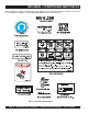
OPERATION AND PARTS MANUAL HERE'S HOW TO GET HELP PLEASE HAVE THE MODEL AND SERIAL NUMBER ON-HAND WHEN CALLING UNITED STATES Multiquip Corporate Office 18910 Wilmington Ave. Tel. (800) 421-1244 Carson, CA 90746 Fax (800) 537-3927 Contact: mq@multiquip.com Mayco Parts 800-306-2926 Fax: 800-672-7877 310-537-3700 Fax: 310-637-3284 Service Department 800-421-1244 Fax: 310-537-4259 310-537-3700 MQ Parts Department 800-427-1244 310-537-3700 MEXICO UNITED KINGDOM MQ Cipsa Carr. Fed. Mexico-Puebla KM 126.