OPERATION AND PARTS MANUAL MODEL GA-2.5H PORTABLE AC GENERATOR (HONDA GASOLINE ENGINE) S/N 5496762 AND BELOW S/N 5496763 AND ABOVE Revision #5 (03/04/08) To find the latest revision of this publication, visit our website at: www.multiquip.com THIS MANUAL MUST ACCOMPANY THE EQUIPMENT AT ALL TIMES.
PAGE 2 — GA-2.5H A.C. GENERATOR — OPERATION & PARTS MANUAL — REV.
NOTE PAGE GA-2.5H A.C. GENERATOR — OPERATION & PARTS MANUAL — REV.
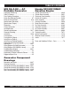
TABLE OF CONTENTS MQ GA-2.5H — AC Portable Generator Honda GX160K1EMA2 Gasoline Engine Proposition 65 Warning .............................................. 2 Table Of Contents ...................................................... 4 Parts Ordering Procedures ........................................ 5 Safety Alert Message Symbols .............................. 6-7 Rules for Safe Operation ...................................... 8-10 Specifications (Generator) .......................................
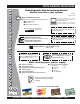
www.multiquip.com PARTS ORDERING PROCEDURES Ordering parts has never been easier! Choose from three easy options: Effective: January 1st, 2006 Best Deal! Order via Internet (Dealers Only): If you have an MQ Account, to obtain a Username and Password, E-mail us at: parts@multiquip.com. Order parts on-line using Multiquip’s SmartEquip website! ■ View Parts Diagrams ■ Order Parts ■ Print Specification Information To obtain an MQ Account, contact your District Sales Manager for more information.
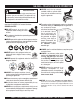
GA-2.5H — SAFETY MESSAGE ALERT SYMBOLS FOR YOUR SAFETY AND THE SAFETY OF OTHERS! HAZARD SYMBOLS Safety precautions should be followed at all times when operating this equipment. Failure to read and understand the Safety Messages and Operating Instructions could result in injury to yourself and others. Potential hazards associated with the operation of a MQ GA-2.
GA-2.5H — SAFETY MESSAGE ALERT SYMBOLS CAUTION Rotating Parts Hazards NEVER operate equipment with covers, or guards removed. Keep fingers, hands, hair and clothing away from all moving parts to prevent injury. CAUTION CAUTION Equipment Damage Hazards Other important messages are provided throughout this manual to help prevent damage to your portable generator, other property, or the surrounding environment.
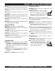
GA-3.6H— RULES FOR SAFE OPERATION DANGER Read this manual! Failure to follow instructions in this manual may lead to serious injury or even death! This equipment is to be operated by trained and qualified personnel only! This equipment is for industrial use only. The following safety guidelines should always be used when operating the MQ GA-2.5H Portable Generator: GENERAL SAFETY ■ DO NOT operate or service this equipment before reading this entire manual.
GA-2.5H — RULES FOR SAFE OPERATION ■ ALWAYS be sure the operator is familiar with proper safety precautions and operation techniques before using generator. ■ NEVER leave the generator unattended, turn off engine when unattended. ■ Unauthorized equipment modifications will void all warranties. ■ ALWAYS ensure generator is on level ground before use. ■ DO NOT place hands or fingers inside generator engine compartment when engine is running.
GA-2.5H — RULES FOR SAFE OPERATION DANGER-ELECTROCUTION HAZARDS During operation of this generation, there exists the possibility of electrocution, electrical shock or burn, which can cause severe bodily harm or even DEATH! Emergencies ■ ALWAYS know the location of the nearest fire extinguisher. ■ ALWAYS know the location of the nearest first aid kit. To avoid these hazards: NEVER use damaged or worn cables when connecting equipment to the generator.
GA-2.5H — —SPECIFICATIONS (GENERATOR) GA-2.5H OPERATION AND SAFETY DECALS Table 1. Specifications (Generator) Model Type Excitation GA-2.5H Brushless Revolving Field Type Solid State, Statically Excited System AC Generator Speed Cooling System Fuel Capacity 60 Cycle AC Power Source 3,600 RPM Self-Ventilation 3.17 gallons (12 liters) Continuous Output 2.2 kW Stanby Output 2.5 kW Rated Voltage 120V Current Max/Continuous (120V) Phase Frequency Power Factor Dimensions Approximate (L x W x H) 20.
GA-2.5H — SPECIFICATIONS (ENGINE) Table 2. Specifications (Engine) Model Type HONDA GX-160K1EMA2 Air-cooled 4 stroke, Single Cylinder, OHV, Horizontal Shaft Gasoline Engine Bore X Stroke 2.7 in. x 1.8 in. (68 mm x 45 mm) Displacement 163 cc (9.9 cu-in) Max Output 5.5 H.P./3600 R.P.M. Engine/Electric Motor Fuel Tank Capacity Fu e l Lube Oil Capacity Speed Control Method Star ting Method Dimension (L x W x H) Dry Net Weight NOTE Approx. 0.95 U.S. gallons (3.6 liters) Unleaded Automobile Gasoline 0.
GA-2.5H — DIMENSIONS Figure 1. Dimensions GA-2.5H A.C. GENERATOR — OPERATION & PARTS MANUAL — REV.
GA-2.5H — GENERAL INFORMATION WARNING Before connecting this generators to any building’s electrical system, a licensed electrician must install an isolation (transfer) switch. Serious injury or death may result without this transfer switch. GA-2.5H FAMILIARIZATION Generator The Multiquip GA-2.5H generator has been designed as a portable dual purpose power source for 60 Hz (single phase) lighting facilities, power tools, submersible pumps and other industrial and construction machinery.
GA-2.5H — LOAD APPLICATION Single Phase Load — 60 Hz Always be sure to check the nameplate on the generators and equipment to insure the wattage, amperage and frequency requirements are satisfactorily supplied by the generators for operating the equipment. Generally, the wattage listed on the nameplate of the equipment is its rated output.
GA-2.5H — CONTROLS AND INDICATORS Figure 2A. Generator Components 1. 120V Output Receptacle – This NEMA L5- 20R twistlock receptacle will provide 120V, 20 amps, 60 Hz. Applies to units with S/N 5496763 and above. 6. ON-OFF Switch – place engine ON/OFF switch in the "ON" position for normal operation. To turn- off the generator place switch in the "OFF" position. 2. GFCI Receptacle – This 5-20R duplex receptacle will provide 120V at all times. 7. 3.
GA-2.5H — CONTROLS AND INDICATORS Figure 2B. Generator Components 8. Generator Housing – Contains the rotor, rectifer field coil assembly, aramature, bearings and other components that make up generator asembly. 15. Fuel Cock Lever – Turn this lever downward to start (down)the flow of fuel to the carburetor. Turn upward to stop (up) the flow of fuel. 9. Spark Plug – Provides spark to the ignition system. Set spark plug gap to 0.6 - 0.7 mm (0.024 - 0.028 inch). Clean spark plug once a week. 16.
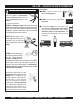
MQ GA-2.5H — GENERATOR REFUELING DANGER Adding fuel to the tank should be done only when the engine is stopped and has had an opportunity to cool down. In the event of a fuel spill, DO NOT attempt to start the engine until the fuel residue has been completely wiped up, and the area surrounding the engine is dry. If generator is placed in a truck bed with a plastic liner, REMOVE generator from truck bed and place on ground (Figure 3) to refuel.
GA-2.5H — INSTALLATION Outdoor Installation Indoor Installation Install the generator in a area that is free of debris , bystanders, and overhead obstructions. Make sure the generator is on secure level ground so that it cannot slide or shift around. Also install the generator in a manner so that the exhaust will not be discharged in the direction of nearby homes. Exhaust gases from gasoline engines are extremely poisonous.
GA-2.5H — INSTALLATION Connecting the Ground The nut and ground terminal on the generator should always be used to connect the generator to a suitable ground. The ground cable should be #8 size wire minimum. At the generator, connect the terminal of the ground cable between the lock washer and the nut (Figure 4) and tighten the nut fully. Connect the other end of the ground cable to a suitable earth ground (ground rod). Figure 4. Generator Grounding PAGE 20 — GA-2.5H A.C.
GA-2.5H — PRE-INSPECTION General Inspection Prior to Operation Extension Cable Ground Power Tools When electric power is to be provided to various tools or loads at some distance from the generator, extension cords are normally used. Cables should be sized to allow for distance in length and amperage so that the voltage drop between the generator and point of use (load) is held to a minimum. Use the cable selection chart (Table 4) as a guide for selecting proper cable size.
GA-2.5H — PRE-INSPECTION (ENGINE) CAUTION NEVER operate the generator in a confined area or enclosed area structure that does not provide ample free flow of air. Figure 7. Engine Oil Dipstick (Oil Level) ALWAYS wear approved eye and hearing protection before operating the generator. Table 5. Oil Type Before Starting Season Temperature Oil Type 1. Read safety instructions at the beginning of manual. Summer 25°C or Higher SAE 10W-30 2.
GA-2.5H — INITIAL START-UP (ENGINE) CAUTION DO NOT attempt to operate this generator until the Safety, General Information and Inspection sections of this manual have been read and thoroughly understood. 3. Place the choke lever (Figure 11) in the "OPEN " position if starting a warm engine or the temperature is warm. 4. Place the engine ON/OFF switch (Figure 12) in the "ON " position. This section is intended to assist the operator with the initial start-up of the trash generator.
GA-2.5H — INITIAL START-UP ENGINE/OPERATION 6. If the engine has started, slowly return the choke lever (Figure 11 ) to the “OPEN” position. If the engine has not started repeat steps 1 through 5. 7. Before the generator is placed into operation, run the engine for 3-5 minutes. Check for abnormal smells, fuel leaks, and noises that would associate with lose components. 8. Refer to the AC voltmeter (Figure 14) on the control panel.
MQ GA-2.5H — PREPARATION FOR LONG -TERM STORAGE Generator Storage For storage of the generating set for over 30 days, the following is required: ■ Drain the fuel tank completely, or add STA-BIL to the fuel. ■ Run the engine until the gasoline in the carburetor is completely consumed. ■ Completely drain the oil from the crankcase and refill with fresh oil. ■ Remove the spark plug, pour 2 or 3 cc of SAE 30 oil into the cylinder and crank slowly to distribute the oil.
MQ GA-2.5H — MAINTENANCE (ENGINE) Use Table 6 as a general maintenance guideline when servicing your engine. For more detail engine maintenance information, refer to the engine owner's manual supplied with your engine. Table 6. Engine Maintenance Schedule DESCRIPTION (3) OPERATION BEFORE CHECK X FIRST EVERY MONTH 3 MONTHS OR OR 10 HRS. 25 HRS. EVERY 6 MONTHS OR 50 HRS. EVERY YEAR OR 100 HRS. EVERY 2 YEARS OR 200 HRS.
MQ GA-2.5H — MAINTENANCE (ENGINE) Maintenance Perform the scheduled maintenance procedures as defined by Table 6 and below: DAILY ■ Thoroughly remove dirt and oil from the engine and control area. Clean or replace the air cleaner elements as necessary. Check and retighten all fasteners as necessary. Check the gearbox for oil leaks. Repair or replace as needed. WEEKLY ■ Remove the fuel filter cap and clean the inside of the fuel tank. ■ Remove or clean the filter at the bottom of the tank.
GA-2.5H — WIRING DIAGRAM (S/N 5496762 AND BELOW) Figure 22. Generator/Engine Wiring Diagram (S/N 5496762 and below) PAGE 28 — GA-2.5H A.C. GENERATOR — OPERATION & PARTS MANUAL — REV.
GA-2.5H — WIRING DIAGRAM (S/N 5496763 AND ABOVE) Figure 23. Generator/Engine Wiring Diagram (S/N 5496763 and above) GA-2.5H A.C. GENERATOR — OPERATION & PARTS MANUAL — REV.
GA-2.5H — TROUBLESHOOTING (ENGINE) Practically all breakdowns can be prevented by proper handling and maintenance inspections, but in the event of a breakdown, please take a remedial action following the diagnosis based on the Engine Troubleshooting (Table 7) information shown below and on the proceeding page. If the problem cannot be remedied, please leave the unit just as it is and consult our company's business office or service plant. TABLE 7.
GA-2.5H — TROUBLESHOOTING (ENGINE) TABLE 7. ENGINE TROUBLESHOOTING (CONTINUED) SYMPTOM Insufficient power output "compression" and overheats Burns to much fuel Exhaust color is continiously "WHITE" Exhaust color is continiously "BLACK" POSSIBLE PROBLEM SOLUTION Malfunction in blower? Check or replace blower. Air in-take filter clogged? Clean or replace air in-take filter. Over accumulation of exhaust products? Clean and check valves. Check muffler, replace if necessary.
GA-2.5H — TROUBLESHOOTING (GENERATOR) Practically all generator breakdowns can be prevented by proper handling and maintenance inspections, but in the event of a breakdown, please take a remedial action following the diagnosis based on the Generator Troubleshooting (Table 8) information shown below and on the preceding page. If the problem cannot be remedied, please leave the unit just as it is and consult our company's business office or service plant. TABLE 8.
NOTE PAGE GA-2.5H A.C. GENERATOR — OPERATION & PARTS MANUAL — REV.
GA-2.5H — EXPLANATION OF CODE IN REMARKS COLUMN The following section explains the different symbols and remarks used in the Parts section of this manual. Use the help numbers found on the back page of the manual if there are any questions. The contents and part numbers listed in the parts section are subject to change without notice. Multiquip does not guarantee the availibility of the parts listed. * * Numbers Used - Item quantity can be indicated by a number, a blank entry, or A/R.
GA-2.5H — SUGGESTED SPARE PARTS GA-2.5H 1 TO 5 UNITS WITH HONDA GX160K1EMA2 ENGINE 1 to 5 Units Qty. P/N Description 5 ............ 9807956846 .......... SPARK PLUG 1 ............ 15510ZE1033 ....... OIL LEVEL SWITCH 1 ............ 15600ZE1003 ....... DIPSTICK 1 ............ 36100ZE1015 ....... STOP SWITCH 5 ............ 17211ZBZ000 ....... ELEMENT AIR 5 ............ 28462ZH8003 ....... ROPE, RECOIL STARTER 2 ............ 0601804887 .......... CIRCUIT BREAKER 2 ............ 0601812597 ..........
GA-2.5H — NAMEPLATE AND DECALS. Machine Safety Decals The GA-2.5H portable generator is equipped with a number of safety decals (see below). These decals are provided for operator safety and maintenance information. The illustration below shows these decals as they appear on the machine. Should any of these decals become unreadable, replacements can be obtained from your dealer PAGE 36 — GA-2.5H A.C. GENERATOR — OPERATION & PARTS MANUAL — REV.
GA-2.5H — NAMEPLATE AND DECALS. NAME PLATE ASSY. NO. PART NO. 1 7930505002 1 A2511201002 2 87528ZB2630 3 1980680004 4 5 87533ZC0630 6 7980615403 6 A2561000003 7 8700611804 8 8700611904 9 0800628504 10 7900638204 10 A9521200004 11 7900636004 12 0820610404 13 35137 14 0820610804 PART NAME QTY. REMARKS DECAL; CONTROL PANEL ..................................... 1 ............... S/N 5496762 AND BELOW DECAL; CONTROL PANEL ..................................... 1 ...............
MQ GA-2.5H — GENERATOR ASSY . GENERATOR ASSY. PAGE 38 — GA-2.5H A.C. GENERATOR — OPERATION & PARTS MANUAL — REV.
MQ GA-2.5H — GENERATOR ASSY . GENERATOR ASSY. NO PART NO 1 7931000203 1-1 * 0601823213 1-2 1-2 0601822638 1-3 0603000040 * 7681017104 2 3 0801086004 4 0040008000 5 7921341803 5 A2135000203 6 7931315002 7 7931315102 8 7875021523 9 7681331003 10 7681344204 11 0040006000 12 0041206000 13 7871329514 14 0601851760 15 0013608025 15 0013608020 15A 0040008000 16 7935420104 17 0017106016 18 7935420004 19 0207206000 20 0017108020 PART NAME QTY. REMARKS ROTOR ASSY. ............................... 1 .............
MQ GA-2.5H — CONTROL BOX ASSY. S/N 5496762 AND BELOW CONTROL BOX ASSY. (S/N 5496762 AND BELOW) PAGE 40 — GA-2.5H A.C. GENERATOR — OPERATION & PARTS MANUAL — REV.
MQ GA-2.5H — CONTROL BOX ASSY. S/N 5496762 AND BELOW CONTROL BOX ASSY. (S/N 5496762 AND BELOW) NO. 1 2 3 4 5 6 7 8 9 10 11 12 13 13A 14 15 PART NO. 7931800203 0801354504 0601823204 0027103020 011106015 7931810303 0601800258 0038303000 0601804887 3011816004 0027104010 0601812597 0027104010 0038404000 0601815103 0017105010 PART NAME QTY. REMARKS CONTROL BOX 1 GROMMET 1 RECTIFIER .......................................... 1 ........... S5 VB60 MACHINE SCREW 1 HEX. HEAD BOLT ................................
MQ GA-2.5H — CONTROL BOX ASSY. S/N 5496763 AND ABOVE CONTROL BOX ASSY. (S/N 5496763 AND ABOVE) PAGE 42 — GA-2.5H A.C. GENERATOR — OPERATION & PARTS MANUAL — REV.
MQ GA-2.5H — CONTROL BOX ASSY. S/N 5496763 AND ABOVE CONTROL BOX ASSY. (S/N 5496763 AND ABOVE) NO PART NO PART NAME QTY. REMARKS 1 A0101000103 CONTROL BOX 1 2 0801354504 GROMMET 1 3 0601823204 RECTIFIER ............................................... 1 ................. S5VB60 4 0027103012 MACHINE SCREW 1 5 A2224000103 CONTROL PANEL 1 6 0601804887 CIRCUIT BREAKER ................................. 1 .................
MQ GA-2.5H — PIPE FRAME ASSY. S/N 5496762 AND BELOW PIPE FRAME ASSY. (S/N 5496762 AND BELOW) PAGE 44 — GA-2.5H A.C. GENERATOR — OPERATION & PARTS MANUAL — REV.
MQ GA-2.5H — PIPE FRAME ASSY. S/N 5496762 AND BELOW PIPE FRAME ASSY. (S/N 5496762 AND BELOW) NO. 1 2 3 4 5 6 7 8 9 10 10- 1 10- 2 11 12 13 14 15 16 17 18 19 20 21 21A 22 23 24 PART NO. PART NAME QTY. REMARKS 7935400302 PIPE FRAME 1 0801886104 WASHER 2 7935419204 RUBBER SUSPENSION 2 7935419304 RUBBER SUSPENSION 2 020108060 HEX. NUT ............................................. 8 ...........
MQ GA-2.5H — PIPE FRAME ASSY. S/N 5496763 AND ABOVE PIPE FRAME ASSY. (S/N 5496763 AND ABOVE) PAGE 46 — GA-2.5H A.C. GENERATOR — OPERATION & PARTS MANUAL — REV.
MQ GA-2.5H — PIPE FRAME ASSY. S/N 5496763 AND ABOVE PIPE FRAME ASSY. (S/N 5496763 AND ABOVE) NO. 1 2 3 4 5 6 7 8 9 10 10- 1 10- 2 11 12 13 14 15 16 17 18 19 20 21 22 23 PART NO. A2417000202 7935419204 020108060 7935419304 020108060 A2364000002 A9924800014 A9924800004 0602125034 16950898632 16081471831 16952883005 950014518040 9500202080 7855525514 7855525604 011208030 011008020 7935421004 0017106016 0017106016 0019206016 0011308020 0040008000 020108060 PART NAME QTY.
HONDA GX160K1EMA2 ENGINE — CYLINDER HEAD ASSY. CYLINDER HEAD ASSY. PAGE 48 — GA-2.5H A.C. GENERATOR — OPERATION & PARTS MANUAL — REV.
HONDA GX160K1EMA2 ENGINE — CYLINDER HEAD ASSY. CYLINDER HEAD ASSY. NO 1 2 * 3 * 4 * 5 6 7 8 9 10 11 12 13 14 14 PART NO 12210ZH8020 12204ZE1306 12205ZE1315 12216ZE5300 12251ZF1800 12310ZE1010 12391ZE1000 15721732000 90013883000 90043ZB2003 90047ZE1000 9430110160 957230806000 9807956846 9807956855 PART NAME QTY. REMARKS HEAD COMP., CYLINDER ........................ 1 ......... INCLUDES ITEMS W/ * GUIDE, IN. VALVE (OVER SIZE) 1 GUIDE, IN.
HONDA GX160K1EMA2 ENGINE — CYLINDER BARREL ASSY. CYLINDER BARREL ASSY. PAGE 50 — GA-2.5H A.C. GENERATOR — OPERATION & PARTS MANUAL — REV.
HONDA GX160K1EMA2 ENGINE — CYLINDER BARREL ASSY. CYLINDER BARREL ASSY. NO 2 3 4 PART NO 12000ZH8406 15510ZE1033 16510ZE1000 4 16506ZL0000 5 * 6 * 7 * 8 9 12 13 14 15 16# 17# 18 19 20 21 22 23 16511ZE1000 16512ZE1000 16513ZE1000 16531ZE1000 16541ZE1000 90131ZE1000 90451ZE1000 90601ZE1000 90602ZE1000 91001ZF1003 91201Z0T801 91353671004 9405010000 9410106800 9425108000 957010601200 06111ZH8405 PART NAME QTY. REMARKS BARREL ASSY, CYLINDER ................................ 1 .........
HONDA GX160K1EMA2 ENGINE — CRANKCASE COVER ASSY. CRANKCASE COVER ASSY. PAGE 52 — GA-2.5H A.C. GENERATOR — OPERATION & PARTS MANUAL — REV.
HONDA GX160K1EMA2 ENGINE — CRANKCASE COVER ASSY. CRANKCASE COVER ASSY. NO 1 3 4 5 8# 9 * 10 11 12 * PART NO 11300ZE1634 11381ZH8801 15600ZE1003 15600ZG4003 15625ZE1003 91201Z0T801 9430108140 957010803200 961006205000 PART NAME QTY. REMARKS COVER ASSY, CRANKCASE ............................. 1 ............ INCLUDES ITEMS W/ * GASKET, CASE COVER 1 CAP ASSY, OIL FILLER ...................................... 1 ............
HONDA GX160K1EMA2 ENGINE — CRANKSHAFT ASSY. CRANKSHAFT ASSY. PAGE 54 — GA-2.5H A.C. GENERATOR — OPERATION & PARTS MANUAL — REV.
HONDA GX160K1EMA2 ENGINE — CRANKSHAFT ASSY. CRANKSHAFT ASSY. NO 1 PART NO 13310ZB2000 PART NAME CRANKSHAFT (VE-TYPE) QTY. REMARKS 1 GA-2.5H A.C. GENERATOR — OPERATION & PARTS MANUAL — REV.
HONDA GX160K1EMA2 ENGINE — PISTON ASSY. PISTON ASSY. PAGE 56 — GA-2.5H A.C. GENERATOR — OPERATION & PARTS MANUAL — REV.
HONDA GX160K1EMA2 ENGINE — PISTON ASSY. PISTON ASSY. NO 1 1 1 1 2 2 2 2 3 4 5 6 PART NO 13010ZF1023 13011ZF1023 13012ZF1023 13013ZF1023 13101ZH8010 13101ZH8010 13103ZH8000 13102ZH8010 13111ZE1000 132000ZE1010 90001ZE1000 90551ZE1000 PART NAME RING SET, PISTON (STD) RING SET, PISTON (0.25) RING SET, PISTON (0.50) RING SET, PISTON (0.75) PISTON (STD) PISTON (0.25) PISTON (0.50) PISTON (0.75) PIN, PISTON ROD ASSY, CONNECTING BOLT, CONNECTING ROD CLIP, PISTON PIN, 18MM QTY.
HONDA GX160K1EMA2 ENGINE — CAMSHAFT ASSY. CAMSHAFT ASSY. PAGE 58 — GA-2.5H A.C. GENERATOR — OPERATION & PARTS MANUAL — REV.
HONDA GX160K1EMA2 ENGINE — CAMSHAFT ASSY. CAMSHAFT ASSY. NO 1 1 2 3 4 5 6 7 8 9 10 11 12 13 14 15 18 PART NO 14100ZE1812 14100ZL0000 14410ZE1010 14431ZE1000 14441ZE1000 14451ZE1013 14568ZE1000 14711ZF1000 14721ZF1000 14751ZF1000 14771ZE1000 14773ZE1000 14781ZE1000 14791ZE1010 90012ZE0010 90206ZE1000 12209ZH8003 PART NAME QTY. REMARKS CAM SHAFT ASSY. ............................................. 1 ............ UP TO S/N 4913229 CAM SHAFT ASSY. ............................................. 1 ............
HONDA GX160K1EMA2 ENGINE — RECOIL STARTER ASSY. RECOIL STARTER ASSY. PAGE 60 — GA-2.5H A.C. GENERATOR — OPERATION & PARTS MANUAL — REV.
HONDA GX160K1EMA2 ENGINE — RECOIL STARTER ASSY. RECOIL STARTER ASSY.
HONDA GX160K1EMA2 ENGINE — FAN COVER ASSY. FAN COVER ASSY. PAGE 62 — GA-2.5H A.C. GENERATOR — OPERATION & PARTS MANUAL — REV.
HONDA GX160K1EMA2 ENGINE — FAN COVER ASSY. FAN COVER ASSY. NO 3 * 4 7 7 7 10 10 11 12 PART NO 16584883300 19610ZE1000ZC 19611ZH8820 19612ZH8821 19612ZH8830 19613ZE1010 90601ZH7013 19630ZB2000 19640ZB2010 12 19640ZH8R60 13 14 14 17 18 19 * 19 * 21 23 24 32197ZH8003 36100ZE1015 36100ZH7003 90013883000 90022888010 93500050350A 93500050400G 957010600800 34150ZH7003 957010600800 PART NAME QTY. REMARKS SPRING, CONTROL ADJUSTING 1 COVER, FAN “NH1” BLACK 1 PLATE, SIDE ALERT & LAMP ............ 1 .............
HONDA GX160K1EMA2 ENGINE — CARBURETOR ASSY. CARBURETOR ASSY. PAGE 64 — GA-2.5H A.C. GENERATOR — OPERATION & PARTS MANUAL — REV.
HONDA GX160K1EMA2 ENGINE — CARBURETOR ASSY. CARBURETOR ASSY. NO 1#%+ 2 * 3 * 4 * 4 * 6 * 7 8 9 * 10 11 * 12 * 13 14 15 16 17 18 < 19 19 19 * 20 * PART NO 16010ZB1015 16011ZE0005 16013ZE0005 16015ZE0831 16015ZE1811 16016ZH7W01 16024ZE1811 16028ZE0005 16044ZE0005 16100ZH8E81 16124ZE0005 16166ZH8E80 16211ZE1000 16212ZH8800 16221ZH8801 16269ZE1800 16610ZB2000 9430520122 99101ZH80700 99101ZH80720 99101ZH80750 99204ZE00350 PART NAME QTY. REMARKS GASKET SET 1 VALVE SET, FLOAT 1 FLOAT SET 1 CHAMBER SET, FLOAT ..
HONDA GX160K1EMA2 ENGINE — AIR CLEANER ASSY. AIR CLEANER ASSY. PAGE 66 — GA-2.5H A.C. GENERATOR — OPERATION & PARTS MANUAL — REV.
HONDA GX160K1EMA2 ENGINE — AIR CLEANER ASSY. AIR CLEANER ASSY. NO 1 2 3 4 5 6 7 8 9 PART NO 17211ZB2000 17212ZB2000 17220ZB2000 17231ZB2000 17239ZB2000 17252ZB2000 90115459770 9405006080 957010601000 PART NAME ELEMENT, AIR CLEANER SEPARATOR, AIR CLEANER CASE COMP., AIR CLEANER COVER AIR CLEANER STAY AIR CLEANER SEAL, AIR CLEANER BOLT, SETTING BOLT, FLANGE, 6MM BOLT, FLANGE, 6X10 QTY. 1 1 1 1 1 1 4 REMARKS 2 1 GA-2.5H A.C. GENERATOR — OPERATION & PARTS MANUAL — REV.
HONDA GX160K1EMA2 ENGINE — MUFFLER ASSY. MUFFLER ASSY. PAGE 68 — GA-2.5H A.C. GENERATOR — OPERATION & PARTS MANUAL — REV.
HONDA GX160K1EMA2 ENGINE — MUFFLER ASSY. MUFFLER ASSY. NO 1 2 3 4 5 6 8 9 PART NO 18310ZB3C00 18320ZB2000 18325ZH8T90 18329ZB2000 18330ZH8T90 18355898630 18381ZE1800 18381ZH8800 PART NAME MUFFLER COMP. PROTECTOR, MUFFLER OUTER PROTECTOR, MUFFLER INNER SEAL, MUFFLER PROTECTOR PIPE COMP., EX ARRESTER, SPARK GASKET, MUFFLER GASKET, MUFFLER QTY. 1 1 1 2 1 1 1 1 REMARKS GA-2.5H A.C. GENERATOR — OPERATION & PARTS MANUAL — REV.
HONDA GX160K1EMA2 ENGINE — FLYWHEEL ASSY. PAGE 70 — GA-2.5H A.C. GENERATOR — OPERATION & PARTS MANUAL — REV.
HONDA GX160K1EMA2 ENGINE — FLYWHEEL ASSY. FLYWHEEL ASSY. NO 1 2 3 4 5 PART NO 13331357000 19511ZE1000 28451ZH8003 31100ZE1811 90201878003 PART NAME KEY, SPECIAL WOOD RUFF, 25X18 FAN, COOLING PULLEY, STARTER FLYWHEEL (LAMP) NUT, SPECIAL, 14MM QTY. 1 1 1 1 1 REMARKS GA-2.5H A.C. GENERATOR — OPERATION & PARTS MANUAL — REV.
HONDA GX160K1EMA2 ENGINE — IGNITION COIL ASSY. IGNITION COIL ASSY. PAGE 72 — GA-2.5H A.C. GENERATOR — OPERATION & PARTS MANUAL — REV.
HONDA GX160K1EMA2 ENGINE — IGNITION COIL ASSY. IGNITION COIL ASSY. NO 1 2 4 6 7 12 13 14 15 PART NO 30500ZE1043 30700ZE1013 31510ZE1811 31511ZE1000 31512ZE1000 90015883000 90019883000 90121952000 36101ZE1010 PART NAME COIL ASSY., IGNITION CAP ASSY., NOISE SUPPRESSOR COIL ASSY., LAMP (12V25W) CLAMP, WIRE GROMMET, WIRE BOLT, FLANGE, 6X28 BOLT, FLANGE, 5X10 BOLT, FLANGE, 6X25 WIRE, STOP SWITCH QTY. REMARKS 1 1 1 1 1 2 1 2 ` GA-2.5H A.C. GENERATOR — OPERATION & PARTS MANUAL — REV.
HONDA GX160K1EMA2 ENGINE — GOVERNOR/CONTROL ASSY. GOVERNOR/CONTROL ASSY. PAGE 74 — GA-2.5H A.C. GENERATOR — OPERATION & PARTS MANUAL — REV.
HONDA GX160K1EMA2 ENGINE — GOVERNOR/CONTROL ASSY. GOVERNOR/CONTROL ASSY. NO 1 1 2 3 3 3 4 5 6 PART NO 16551ZE0010 16551ZL0010 16555ZE1000 16561ZH8D00 16561ZL0U30 16561ZL0000 16562ZE1020 90015ZE5010 9405006000 PART NAME QTY. REMARKS ARM, GOVERNOR .................................... 1 ......... USE UP TO S/N 4913229 ARM, GOVERNOR .................................... 1 ......... USE FROM S/N 4913230 ROD, GOVERNOR 1 SPRING, GOVERNOR .............................. 1 .........
HONDA GX160K1EMA2 ENGINE — LABELS ASSY. PAGE 76 — GA-2.5H A.C. GENERATOR — OPERATION & PARTS MANUAL — REV.
HONDA GX160K1EMA2 ENGINE — LABELS ASSY. IGNITION COIL ASSY. NO 1 12 21 PART NO 87521ZH8020 87528ZB2630 87533ZC0630 PART NAME EMBLEM, 5.5 HP DECAL, CHOKE DECAL, AIR CLEANER QTY. 1 1 1 REMARKS GA-2.5H A.C. GENERATOR — OPERATION & PARTS MANUAL — REV.
TERMS AND CONDITIONS OF SALE — PARTS PAYMENT TERMS 5. Parts must be in new and resalable condition, in the original Multiquip package (if any), and with Multiquip part numbers clearly marked. 6. The following items are not returnable: Terms of payment for parts are net 30 days. FREIGHT POLICY All parts orders will be shipped collect or prepaid with the charges added to the invoice. All shipments are F.O.B. point of origin.
NOTE PAGE GA-2.5H A.C. GENERATOR — OPERATION & PARTS MANUAL — REV.
OPERATION AND PARTS MANUAL HERE’S HOW TO GET HELP PLEASE HAVE THE MODEL AND SERIAL NUMBER ON-HAND WHEN CALLING UNITED STATES Multiquip Corporate Office 18910 Wilmington Ave. Carson, CA 90746 Contact: mq@multiquip.com Mayco Parts 800-306-2926 310-537-3700 Service Department 800-421-1244 310-537-3700 Tel.