OPERATION AND PARTS MANUAL MODEL GA4.5R/GA4.5RA PORTABLE AC GENERATOR (ROBIN GASOLINE ENGINE) Revision #1 (11/27/06) THIS MANUAL MUST ACCOMPANY THE EQUIPMENT AT ALL TIMES.
PAGE 2 — GA-4.5R/GA-4.5RA A.C. GENERATOR— OPERATION & PARTS MANUAL — REV.
NOTE PAGE GA-4.5R/GA-4.5RA A.C. GENERATOR — OPERATION & PARTS MANUAL — REV.
TABLE OF CONTENTS GA-4.5R/GA-4.5RA — AC Portable Generators ROBIN EX270D Engine (EPA) California Proposition 65 Warning ............................. 3 Table Of Contents ..................................................... 4 Parts Ordering Procedures ....................................... 5 Safety Alert Message Symbols .............................. 6-7 Rules for Safe Operation ..................................... 8-10 Specifications ..........................................................
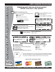
www.multiquip.com PARTS ORDERING PROCEDURES Ordering parts has never been easier! Choose from three easy options: Best Deal! Order via Internet (Dealers Only): If you have an MQ Account, to obtain a Username and Password, E-mail us at: parts@multiquip.com. Order parts on-line using Multiquip’s SmartEquip website! ■ View Parts Diagrams ■ Order Parts ■ Print Specification Information To obtain an MQ Account, contact your District Sales Manager for more information.
GA-4.5R/GA-4.5RA — SAFETY MESSAGE ALERT SYMBOLS FOR YOUR SAFETY AND THE SAFETY OF OTHERS! Safety precautions should be followed at all times when operating this equipment. Failure to read and understand the Safety Messages and Operating Instructions could result in injury to yourself and others.
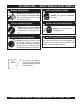
GA-4.5R/GA-4.5RA — SAFETY MESSAGE ALERT SYMBOLS WARNING - ROTATING PARTS NEVER operate equipment with covers, or guards removed. Keep fingers, hands, hair and clothing away from all moving parts to prevent injury. CAUTION - ACCIDENTAL STARTING ALWAYS place the Engine ON/OFF switch in the OFF position and remove the ignition key when the pump is not in use. CAUTION - OVER-SPEED CONDITIONS NEVER tamper with the factory settings of the engine governor or settings.
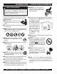
GA-4.5R/GA-4.5RA — RULES FOR SAFE OPERATION DANGER - READ THIS MANUAL! Failure to follow instructions in this manual may lead to serious injury or even DEATH! This equipment is to be operated by trained and qualified personnel only! This equipment is for industrial use only. The following safety guidelines should always be used when operating the GA-4.5R/GA-4.5RA Portable Generators: GENERAL SAFETY ■ DO NOT operate or service this equipment before reading this entire manual.
GA-4.5R/GA-4.5RA — RULES FOR SAFE OPERATION ■ ALWAYS be sure the operator is familiar with proper safety precautions and operation techniques before using generator. ■ NEVER leave the generator unattended, turn off engine when unattended. ■ Unauthorized equipment modifications will void all warranties. ■ ALWAYS ensure generator is on level ground before use. ■ DO NOT place hands or fingers inside generator engine compartment when engine is running.
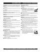
GA-4.5R/GA-4.5RA — RULES FOR SAFE OPERATION DANGER -ELECTROCUTION HAZARDS During operation of this generation, there exists the possibility of electrocution, electrical shock or burn, which can cause severe bodily harm or even DEATH! Emergencies ■ ALWAYS know the location of the nearest fire extinguisher. ■ ALWAYS know the location of the nearest first aid kit. To avoid these hazards: NEVER use damaged or worn cables when connecting equipment to the generator.
GA-4.5R/GA-4.5RA — SPECIFICATIONS Table 1. Specifications MODEL Type Frequency (Hz) GENERATOR 2-Pole, Brushless Type Revolving Field 60 Continuous Output (kW) 3 .7 0 Maximum Output (kW) 4.5 Voltages (VAC) 120/240 Max/Continuous Amps 120 VAC 37.5/30.8 Max/Continuous Amps 240 VAC 18.75/15.4 Rated Speed (RPM) Power Factor Dimension (L x W x H) in. (mm) Dry Net Weight lbs. (kg) Includes Engine Model (Engine Specification) Type Displacement (cc) ENGINE GA-4.5R/GA-4.5RA 3600 1.0 23 X 18.5 X 20.
GA-4.5R/GA-4.5RA — DIMENSIONS Figure 1. Dimensions PAGE 12 — GA-4.5R/GA-4.5RA A.C. GENERATOR— OPERATION & PARTS MANUAL — REV.
GA-4.5R/GA-4.5RA — GENERAL INFORMATION DANGER - ELECTRICAL SYSTEM HAZARDS Before connecting this generator to any building’s electrical system, a licensed electrician must install an isolation (transfer) switch. Serious damage to the building’s electrical system may occur without this transfer switch. GA-4.5R/GA-4.5RA Familarization General Inspection Prior to Operation This generator has been thoroughly inspected and accepted prior to shipment from the factory.
GA-4.5R/GA-4.5RA — LOAD APPLICATION Single Phase Load Always be sure to check the nameplate on the generator and equipment to insure the wattage, amperage and frequency requirements are satisfactorily supplied by the generator for operating the equipment. Generally, the wattage listed on the nameplate of the equipment is its rated output.
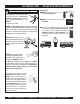
GA-4.5R/GA-4.5RA — CONTROLS AND INDICATORS Figure 2A. Generator Controls and Components 1. Lifting Bail Eye – Attach a rope or chain to this lifting eye when lifting of the generator is required. Never stand underneath the generator while it is being lifted. Place lifting eye in down position when not in use. 5. GFCI Duplex Receptacle – NEMA 5-20R receptacle will provide 120V, 20 amps. The position of the full power switch does not effect the voltage output at the receptacle. The GA-4.
GA-4.5R/GA-4.5RA — CONTROLS AND INDICATORS Figure 2B. Generator Controls and Components (continued) 11. Full Power Switch – The generators are provided with a full power switch. Figures 2C and 2D show simplified wiring diagrams of the dual voltage system.
GA-4.5R/GA-4.5RA — CONTROLS AND INDICATORS Figure 2E. Generator Controls and Components (continued) 12. Choke Lever – Used for starting the engine. Close the choke lever when starting a cold engine or in cold weather conditions. The choke enriches the fuel mixture. Open the choke lever if starting a warm engine or in warm weather conditions. 13. Fuel Cock Lever – Turn this lever downward to start (down)the flow of fuel to the carburetor. Turn upward to stop (up) the flow of fuel. 14.
GA-4.5R/GA-4.5RA — GENERATOR REFUELING DANGER - REFUELING HAZARD Adding fuel to the tank should be done only when the engine is stopped and has had an opportunity to cool down. In the event of a fuel spill, DO NOT attempt to start the engine until the fuel residue has been completely wiped up, and the area surrounding the engine is dry. If generator is placed in a truck bed with a plastic liner, REMOVE generator from truck bed and place on ground (Figure 3) to refuel.
GA-4.5R/GA-4.5RA — INSTALLATION Outdoor Installation Indoor Installation Install the generator in a area that is free of debris , bystanders, and overhead obstructions. Make sure the generator is on secure level ground so that it cannot slide or shift around. Also install the generator in a manner so that the exhaust will not be discharged in the direction of nearby homes. Exhaust gases from gasoline engines are extremely poisonous.
GA-4.5R/GA-4.5RA — INSTALLATION Connecting the Ground The nut and ground terminal on the generator should always be used to connect the generator to a suitable ground. The ground cable should be #8 size wire minimum. At the generator, connect the terminal of the ground cable between the lock washer and the nut (Figure 4) and tighten the nut fully. Connect the other end of the ground cable to a suitable earth ground (ground rod). Figure 4. Generator Grounding PAGE 20 — GA-4.5R/GA-4.5RA A.C.
GA-4.5R/GA-4.5RA — PRE-INSPECTION General Inspection Prior to Operation Extension Cable Ground Power Tools When electric power is to be provided to various tools or loads at some distance from the generator, extension cords are normally used. Cables should be sized to allow for distance in length and amperage so that the voltage drop between the generator and point of use (load) is held to a minimum. Use the cable selection chart (Table 3) as a guide for selecting proper cable size.
GA-4.5R/GA-4.5RA — PRE-INSPECTION (ENGINE) CAUTION NEVER operate the generator in a confined area or enclosed area structure that does not provide ample free flow of air. Figure 7. Engine Oil Dipstick (Oil Level) ALWAYS wear approved eye and hearing protection before operating the generator. Before Starting 1. Read safety instructions at the beginning of manual. 2. Clean the generator, removing dirt and dust, particularly the engine cooling air inlet, carburetor and air cleaner. 3.
GA-4.5R/GA-4.5RA — INITIAL START-UP (ENGINE) CAUTION - READ MANUAL 2. Place the choke lever (Figure 11) in the "CLOSED " position if starting a cold engine. DO NOT attempt to operate this generator until the Safety, General Information and Inspection sections of this manual have been read and thoroughly understood. DO NOT attempt to operate this generator until the Safety, General Information and Inspection sections of this manual have been read and thoroughly understood.
GA-4.5R/GA-4.5RA — INITIAL START-UP ENGINE/OPERATION 6. If the engine has started, slowly return the choke lever (Figure 11 ) to the “OPEN” position. If the engine has not started repeat steps 1 through 6. 7. Before the generator is placed into operation, run the engine for 3-5 minutes. Check for abnormal smells, fuel leaks, and noises that would associate with lose components. Figure 16. AC Voltmeter (120VAC) 8. Place the idle control switch (Figure 14) in the "OFF" (down) position.
GA-4.5R/GA-4.5RA — INITIAL START-UP ENGINE/OPERATION 13. Refer to the AC voltmeter (Figure 19) on the control box. The voltage indicated on the voltmeter should be 240 VAC with no load applied. If desired, verify with a voltmeter that 240V is present at the NEMA L14-20R twist-lock receptacle. In addition verify that 120VAC is present at the NEMA 5-20R GFCI duplex receptacle and the two NEMA L5-20R, L5-30R twist-lock receptacles. 3. Place the main circuit breaker (Figure 21) in the ON position. Figure 21.
GA-4.5R/GA-4.5RA — PREPARATION FOR LONG -TERM STORAGE Generator Storage For storage of the generating set for over 30 days, the following is required: ■ Drain the fuel tank completely, or add STA-BIL to the fuel. ■ Run the engine until the gasoline in the carburetor is completely consumed. ■ Completely drain the oil from the crankcase and refill with fresh oil. ■ Remove the spark plug, pour 2 or 3 cc of SAE 30 oil into the cylinder and crank slowly to distribute the oil.
GA-4.5R/GA-4.5RA — MAINTENANCE (ENGINE) Use Table 5 as a general maintenance guideline when servicing your engine. For more detail engine maintenance information, refer to the engine owner's manual supplied with your engine. Table 5. Engine Maintenance Schedule DESCRIPTION (3) OPERATION BEFORE CHECK X FIRST EVERY MONTH 3 MONTHS OR OR 10 HRS. 25 HRS. EVERY 6 MONTHS OR 50 HRS. EVERY YEAR OR 100 HRS. EVERY 2 YEARS OR 200 HRS.
GA-4.5R/GA-4.5RA — MAINTENANCE (ENGINE) Maintenance Perform the scheduled maintenance procedures as defined by Table 6 and below: DAILY ■ Thoroughly remove dirt and oil from the engine and control area. Clean or replace the air cleaner elements as necessary. Check and retighten all fasteners as necessary. Check the gearbox for oil leaks. Repair or replace as needed. WEEKLY ■ Remove the fuel filter cap and clean the inside of the fuel tank. ■ Remove or clean the filter at the bottom of the tank.
NOTE PAGE GA-4.5R/GA-4.5RA A.C. GENERATOR — OPERATION & PARTS MANUAL — REV.
MQ GA-4.5R — WIRING DIAGRAM Figure 28. Generator/Engine Wiring Diagram (GA-4.5R Only) PAGE 30 — GA-4.5R/GA-4.5RA A.C. GENERATOR— OPERATION & PARTS MANUAL — REV.
MQ GA-4.5RA — WIRING DIAGRAM Figure 29. Generator/Engine Wiring Diagram (GA-4.5RA Only) GA-4.5R/GA-4.5RA A.C. GENERATOR — OPERATION & PARTS MANUAL — REV.
GA-4.5R/GA-4.5RA — TROUBLESHOOTING (ENGINE) Practically all breakdowns can be prevented by proper handling and maintenance inspections, but in the event of a breakdown, please take a remedial action following the diagnosis based on the Engine Troubleshooting (Table 6) information shown below and on the proceeding page. If the problem cannot be remedied, please leave the unit just as it is and consult our company's business office or service plant. TABLE 6.
GA-4.5R/GA-4.5RA — TROUBLESHOOTING (ENGINE) TABLE 6. ENGINE TROUBLESHOOTING (CONTINUED) SYMPTOM Insufficient power output "compression" and overheats Burns to much fuel Exhaust color is continiously "WHITE" Exhaust color is continiously "BLACK" POSSIBLE PROBLEM SOLUTION Malfunction in blower? Check or replace blower. Air in-take filter clogged? Clean or replace air in-take filter. Over accumulation of exhaust products? Clean and check valves. Check muffler, replace if necessary.
GA-4.5R/GA-4.5RA — TROUBLESHOOTING (GENERATOR) Practically all generator breakdowns can be prevented by proper handling and maintenance inspections, but in the event of a breakdown, please take a remedial action following the diagnosis based on the Generator Troubleshooting (Table 7) information shown below and on the preceding page. If the problem cannot be remedied, please leave the unit just as it is and consult our company's business office or service plant. TABLE 7.
NOTE PAGE GA-4.5R/GA-4.5RA A.C. GENERATOR — OPERATION & PARTS MANUAL — REV.
GA-4.5R/GA-4.5RA — EXPLANATION OF CODE IN REMARKS COLUMN The following section explains the different symbols and remarks used in the Parts section of this manual. Use the help numbers found on the back page of the manual if there are any questions. The contents and part numbers listed in the parts section are subject to change without notice . Multiquip does not guarantee the availability of the parts listed. Sample Parts List: NO.
GA-4.5R/GA-4.5RA — SUGGESTED SPARE PARTS GA-4.5R/GA-4.5RA 1 TO 3 UNITS WITH ROBIN EX270D ENGINE 1 to 3 Units Qty. P/N Description 1 ............ A9924800014 ........ CAP, FUEL TANK 1 ............ A9924800004 ........ FUEL FILTER, FUEL TANK 3 ............ 0650140150 .......... SPARK PLUG 3 ............ 2793260907 .......... ELEMENT, AIR CLEANER 1 ............ 2795011008 ..........
GA-4.5R/GA-4.5RA — NAME PLATE AND DECALS NAMEPLATE AND DECALS PAGE 38 — GA-4.5R/GA-4.5RA A.C. GENERATOR— OPERATION & PARTS MANUAL — REV.
GA-4.5R/GA-4.5RA — NAME PLATE AND DECALS NAMEPLATE AND DECALS NO. PART NO. PART NAME QTY. REMARKS 1 A4511200002 DECAL; CONTROL PANEL .................................... 1 ............ A41120000 GA-4.5R ONLY 1 A4511200702 DECAL; CONTROL PANEL .................................... 1 ............ A41120070 GA-4.5RA ONLY 2 NAMEPLATE ......................................................... 1 ............ CONTACT MQ PARTS DEPT. 3 0800628504 DECAL; GROUND .................................................. 1 .....
GA-4.5R/GA-4.5RA — GENERATOR ASSY. GENERATOR ASSY. PAGE 40 — GA-4.5R/GA-4.5RA A.C. GENERATOR— OPERATION & PARTS MANUAL — REV.
GA-4.5R/GA-4.5RA — GENERATOR ASSY. GENERATOR ASSY. NO PART NO 1 A3110200003 1-1 * 7661080003 1-2 0601823213 1-2 0601822638 1-3 * 0071706304 2 7661017104 3 0801086104 4 0040010000 5 A4135000103 6 7661315112 7 7871315022 8 7875021523 9 7661331003 10 7661344204 11 0040008000 12 0041208000 13 7871329514 14 0601851760 15 0013608020 15A 0040008000 PART NAME QTY. REMARKS ROTOR ASSY. ......................................................... 1 ......... INCLUDES ITEMS W/ * FIELD COIL ASSY.
MQ GA-4.5R — CONTROL BOX ASSY. CONTROL BOX ASSY. (GA-4.5R ONLY) PAGE 42 — GA-4.5R/GA-4.5RA A.C. GENERATOR— OPERATION & PARTS MANUAL — REV.
MQ GA-4.5R — CONTROL BOX ASSY. CONTROL BOX ASSY. (GA-4.5R ONLY) NO PART NO PART NAME QTY.
MQ GA-4.5RA — CONTROL BOX ASSY. CONTROL BOX ASSY. (GA-4.5RA ONLY) PAGE 44 — GA-4.5R/GA-4.5RA A.C. GENERATOR— OPERATION & PARTS MANUAL — REV.
MQ GA-4.5RA — CONTROL BOX ASSY. CONTROL BOX ASSY. (GA-4.5RA ONLY) NO PART NO PART NAME QTY.
GA-4.5R/GA-4.5RA — PIPE FRAME ASSY. PIPE FRAME ASSY. PAGE 46 — GA-4.5R/GA-4.5RA A.C. GENERATOR— OPERATION & PARTS MANUAL — REV.
MQ GA-4.5R/GA-4.5RA — PIPE FRAME ASSY. PIPE FRAME ASSY.
ROBIN EX270D20220 — CRANKCASE ASSY. CRANKCASE ASSY.. PAGE 48 — GA-4.5R/GA-4.5RA A.C. GENERATOR— OPERATION & PARTS MANUAL — REV.
ROBIN EX270D20220 — CRANKCASE ASSY. CRANKCASE ASSY.
ROBIN EX270D20110/EX270D20220 — CRANKSHAFT AND PISTON ASSY. CRANKSHAFT AND PISTON ASSY. PAGE 50 — GA-4.5R/GA-4.5RA A.C. GENERATOR— OPERATION & PARTS MANUAL — REV.
ROBIN EX270D20110/EX270D20220 — CRANKSHAFT AND PISTON ASSY. CRANKSHAFT AND PISTON ASSY. NO PART NO PART NAME QTY. REMARKS 10 2792020121 CRANKSHAFT CP 1 50 0180180010 FLANGE NUT 1 70 0323030010 WOODRUFF KEY 1 310 2792250120 CONNECTING ROD ASSY. ......................... 1 ......... INCLUDES ITEM W/ * 320 2792300103 CONNECTING ROD BOLT 2 * 350 2792330103 PISTON PIN 1 360 2792340103 PISTON, STANDARD 1 360 2792340303 PISTON OVERSIZE 0.25 MM 1 360 2792340403 PISTON OVERSIZE 0.
ROBIN EX270D20110/EX270D20220 — GOVERNOR ASSY. GOVERNOR ASSY. PAGE 52 — GA-4.5R/GA-4.5RA A.C. GENERATOR— OPERATION & PARTS MANUAL — REV.
ROBIN EX270D20110/EX270D20220 — GOVERNOR ASSY. GOVERNOR ASSY. NO PART NO 10 2794230113 20 2774220113 30 2794270101 40 2774280113 50 0031305000 60 0130060240 70 0186060020 80 2794250223 310 2774330113 340 2774350103 350 0200060170 355 0217060070 360 0140060180 365 2374500423 370 0021706000 435 2774600101 395 2774390203 396 0131050030 440 0043104080 450 0023506000 480 2774510103 485 0110060020 PART NAME GOVERNOR LEVER GOVERNOR SHAFT GOVERNOR ROD CP ROD SPRING CLIP BOLT AND WASHER ASSY.
ROBIN EX270D20110/EX270D20220 — INTAKE AND EXHAUST ASSY. INTAKE AND EXHAUST ASSY. PAGE 54 — GA-4.5R/GA-4.5RA A.C. GENERATOR— OPERATION & PARTS MANUAL — REV.
ROBIN EX270D20110/EX270D20220 — INTAKE AND EXHAUST ASSY. INTAKE AND EXHAUST ASSY. NO. 10 25 27 34 * 35 * 37 * 38 * 60 70 80 90 95 150 160 163 166 170 200 210 220 224 225 230# 240# 290 540 550 PART NO.
ROBIN EX270D20110/EX270D20220 — MUFFLER ASSY. MUFFLER ASSY. PAGE 56 — GA-4.5R/GA-4.5RA A.C. GENERATOR— OPERATION & PARTS MANUAL — REV.
ROBIN EX270D20110/EX270D20220 — MUFFLER ASSY. MUFFLER ASSY. NO. 310 320 340 350 360 361 365 PART NO. 2793010121 2793420111 2773520103 9802008280 0152060090 0110060010 0110080150 PART NAME QTY. MUFFLER, CP 1 MUFFLER COVER CP 1 GASKET, MUFFLER 26D 9DX58P 0.2T 1 FLANGE NUT 2 TAPPING BOLT, M6X1.0X10L 2 FLANGE BOLT, M6X1.0X8L 1 FLANGE BOLT, M8X1.25X12L 1 REMARKS GA-4.5R/GA-4.5RA A.C. GENERATOR — OPERATION & PARTS MANUAL — REV.
ROBIN EX270D20110/EX270D20220 — AIR CLEANER ASSY. AIR CLEANER ASSY. PAGE 58 — GA-4.5R/GA-4.5RA A.C. GENERATOR— OPERATION & PARTS MANUAL — REV.
ROBIN EX270D20110/EX270D20220 — AIR CLEANER ASSY. AIR CLEANER ASSY. NO. 510 510-200 * 510-220 * 510-250 * 520 * PART NO. 2793262030 2793263308 2793265008 2793264508 2793260907 PART NAME QTY. REMARKS AIR CLEANER ASSY. LOW PROFILE ................. 1 ......... INCLUDES ITEMS W/ * BODY CP 1 GASKET 1 COVER, LOW PROFILE 1 ELEMENT ASSY. 1 GA-4.5R/GA-4.5RA A.C. GENERATOR — OPERATION & PARTS MANUAL — REV.
ROBIN EX270D20110/EX270D20220 — RECOIL STARTER ASSY. RECOIL STARTER ASSY. PAGE 60 — GA-4.5R/GA-4.5RA A.C. GENERATOR— OPERATION & PARTS MANUAL — REV.
ROBIN EX270D20110/EX270D20220 — RECOIL STARTER ASSY. RECOIL STARTER ASSY. NO PART NO 10 2795120101 20 0732005140 40 0110060030 60 2795271111 61 2795270203 80 0016508120 81 0110060020 210 2795020200 210-1 2265071608 * 2795012008 210-2 * 2795011008 210-3 * 2265070108 210-4 * 2795012508 210-5 * 2265073108 210-6 * 2265075208 210-7 * 2795014508 210-11 * 2265074108 210-35 * 2265075318 210-49 * 0110060010 220 PART NAME QTY.
ROBIN EX270D20110/EX270D20220 — CARBURETOR ASSY. CARBURETOR ASSY. PAGE 62 — GA-4.5R/GA-4.5RA A.C. GENERATOR— OPERATION & PARTS MANUAL — REV.
ROBIN EX270D20110/EX270D20220 — CARBURETOR ASSY. CARBURETOR ASSY.
ROBIN EX270D20110/EX270D20220 — FLYWHEEL ASSY. FLYWHEEL ASSY. PAGE 64 — GA-4.5R/GA-4.5RA A.C. GENERATOR— OPERATION & PARTS MANUAL — REV.
ROBIN EX270D20110/EX270D20220 — FLYWHEEL ASSY. FLYWHEEL ASSY. NO PART NO 10 2797923001 11 2797943001 30 0011406250 50 2777310101 60 X660000420 70 0150040090 100 0650140150 110 0655000270 PART NAME FLYWHEEL CP IGNITION COIL CP BOLT & WASHER ASSY. WIRE 2 CP, W/OIL SENSOR SWITCH ASSY. TAPPING SCREW SPARK PLUG, NGK BR6HS SPARK PLUG CAP QTY. 1 1 2 1 1 2 1 1 REMARKS GA-4.5R/GA-4.5RA A.C. GENERATOR — OPERATION & PARTS MANUAL — REV.
TERMS AND CONDITIONS OF SALE — PARTS Effective: February 22, 2006 PAYMENT TERMS 5. Parts must be in new and resalable condition, in the original Multiquip package (if any), and with Multiquip part numbers clearly marked. 6. The following items are not returnable: Terms of payment for parts are net 30 days. FREIGHT POLICY All parts orders will be shipped collect or prepaid with the charges added to the invoice. All shipments are F.O.B. point of origin.
NOTE PAGE GA-4.5R/GA-4.5RA A.C. GENERATOR — OPERATION & PARTS MANUAL — REV.
OPERATION AND PARTS MANUAL HERE'S HOW TO GET HELP PLEASE HAVE THE MODEL AND SERIAL NUMBER ON-HAND WHEN CALLING UNITED STATES Multiquip Corporate Office 18910 Wilmington Ave. Tel. (800) 421-1244 Carson, CA 90746 Fax (800) 537-3927 Contact: mq@multiquip.com Mayco Parts 800-306-2926 Fax: 800-672-7877 310-537-3700 Fax: 310-637-3284 Service Department 800-421-1244 Fax: 310-537-4259 310-537-3700 MQ Parts Department 800-427-1244 310-537-3700 MEXICO UNITED KINGDOM MQ Cipsa Carr. Fed. Mexico-Puebla KM 126.