PARTS AND OPERATION MANUAL OPERATION AND PARTS MANUAL ULTRA-SILENTTM SERIES MODEL DCA-70USJ GENERATOR PARTS LIST NO. M2870400114 Revision #0 (09/16/04) THIS MANUAL MUST ACCOMPANY THE EQUIPMENT AT ALL TIMES.
PAGE 2 — DCA-70USJ — OPERATION AND PARTS MANUAL — REV.
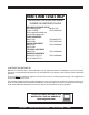
HERE'S HOW TO GET HELP PLEASE HAVE THE MODEL AND SERIAL NUMBER ON-HAND WHEN CALLING MQ POWER CORPORATE OFFICE 18910 Wilmington Ave. 800-421-1244 Carson, CA 90746 FAX: 310-632-2656 Email: mqpower@multiquip.com Internet: www.mqpower.com PARTS DEPARTMENT 800-427-1244 FAX: 800-672-7877 310-537-3700 FAX: 310-637-3284 SERVICE DEPARTMENT 800-835-2551 FAX: 310-638-8046 310-537-3700 TECHNICAL ASSISTANCE 800-835-2551 FAX: 310-638-8046 WARRANTY DEPARTMENT 800-835-2551, EXT. 279 FAX: 310-638-8046 310-537-3700, EXT.
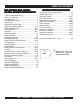
TABLE OF CONTENTS MQ POWER DCA-70USJ UL TRA-SILENT GENERA TOR ULTRA-SILENT GENERATOR California Proposition 65 Warning ..................................... 2 Here's How To Get Help .................................................... 3 Table Of Contents ............................................................. 4 Parts Ordering Procedures ............................................... 5 Specifications ................................................................... 6 Dimensions (Top, Side, Front) ..
PARTS ORDERING PROCEDURES When ordering parts, please supply the following information: ❒ ❒ ❒ ❒ ❒ ❒ ❒ Dealer account number Dealer name and address Shipping address (if different than billing address) Return fax number Applicable model number Quantity, part number and description of each part Specify preferred method of shipment: ✓ FedEx or UPS Ground Note: Unless otherwise indicated by customer, all ✓ FedEx or UPS Second Day or Third Day orders are treated as “Standard Orders”, and will ✓ FedEx or UPS Nex
DCA-70USJ — SPECIFICATIONS Table 1. Generator Specifications Model DCA-70USJ Type Revolving field, self ventilated, open protected type synchronous generator Armature Connection Star with Neutral Zig Zag Phase 3 Single Standby Output 77 KVA (61.6 KW) 44 KW Prime Output 70 KVA (56 KW) 40 KW Voltage 24 0 V o r 4 8 0 V 240/120V Frequency 60 Hz Speed 1800 r pm Power Factor 0.8 1 Aux. AC Power Single Phase, 60 Hz Voltage 120 V Output 4.8 KW (2.4 KW x 2) Table 2.
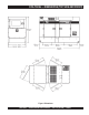
DCA-70USJ — DIMENSIONS (TOP, SIDE AND FRONT) Figure 1. Dimensions DCA-70USJ — OPERATION AND PARTS MANUAL — REV.
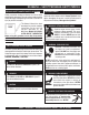
DCA85USJ — SAFETY MESSAGE ALERT SYMBOLS FOR YOUR SAFETY AND THE SAFETY OF OTHERS! Safety precautions should be followed at all times when operating this equipment. Failure to read and understand the Safety Messages and Operating Instructions could result in injury to yourself and others. NOTE This Owner's Manual has been developed to provide complete instructions for the safe and efficient operation of the MQ Power Model DCA-70USJ ULTRA-SILENT™ GENERATOR.
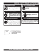
DCA85USJ — SAFETY MESSAGE ALERT SYMBOLS WARNING - ROTATING PARTS NEVER operate equipment with covers, or guards removed. Keep fingers, hands, hair and clothing away from all moving parts to prevent injury. CAUTION - ACCIDENTAL STARTING ALWAYS place the Engine ON/OFF switch in the OFF position and remove the ignition key when the pump is not in use. CAUTION - OVER-SPEED CONDITIONS NEVER tamper with the factory settings of the engine governor or settings.
DCA-70USJ — RULES FOR SAFE OPERATION DANGER - READ THIS MANUAL! Failure to follow instructions in this manual may lead to serious injury or even DEATH! This equipment is to be operated by trained and qualified personnel only! This equipment is for industrial use only. The following safety guidelines should always be used when operating the DCA-70USJ Generator: General Safety: ■ DO NOT operate or service this equipment before reading this entire manual.
DCA-70USJ — RULES FOR SAFE OPERATION Generator Grounding To guard against electrical shock and possible damage to the equipment, it is important to provide a good EARTH ground. Article 250 (Grounding) of the National Electrical Code (NEC) provides guide lines for proper grounding and specifies that the cable ground shall be connected to the grounding system of the building as close to the point of cable entry as practical.
DCA-70USJ — RULES FOR SAFE OPERATION Maintenance Safety ■ The electrical voltage required to operate the generator can cause severe injury or even death through physical contact with live circuits. Turn all circuit breakers OFF before performing maintenance on the generator. ■ NEVER lubricate components or attempt service on a running machine. ■ ALWAYS disconnect the NEGATIVE battery terminal before performing service on the generator.
DCA-70USJ — RULES FOR SAFE OPERATION Towing & Transporting Safety ■ The maximum speed for highway towing is 55 MPH unless posted otherwise. Recommended off-road towing To reduce the possibility of an accident while transporting is not to exceed 15 MPH or less depending on type of the generator on public roads, always make sure the trailer terrain.
DCA-70USJ — GENERATOR DECALS The DCA-70USJ generator is equipped with a number of safety decals (Figures 2 & 3). These decals are provided for operator safety and maintenance information. The illustration below and on the preceding page show the decals as they appear on the machine. Should any of these decals become unreadable, replacements can be obtained from your dealer. Figure 2. Generator Decals PAGE 14 — DCA-70USJ — OPERATION AND PARTS MANUAL — REV.
DCA-70USJ — GENERATOR DECALS Figure 3. Generator Decals (Cont inued) DCA-70USJ — OPERATION AND PARTS MANUAL — REV.
DCA-70USJ — INSTALLATION Figure 4. Typical Generator Grounding Application PAGE 16 — DCA-70USJ — OPERATION AND PARTS MANUAL — REV.
DCA-70USJ — INSTALLATION Outdoor Installation Generator Grounding Install the generator in a area that is free of debris, bystanders, and overhead obstructions. Make sure the generator is on secure level ground so that it cannot slide or shift around. Also install the generator in a manner so that the exhaust will not be discharged in the direction of nearby homes. The installation site must be relatively free from moisture and dust. All electrical equipment should be protected from excessive moisture.
DCA-70USJ — GENERAL INFORMATION DCA-70USJ Series Familiarization Generator The MQ Power Model DCA-70USJ is a 56 kW generator (Figure 5) that is designed as a high quality portable (requires a trailer for transport) power source for telecom sites, lighting facilities, power tools, submersible pumps and other industrial and construction machinery.
DCA-70USJ — MAJOR COMPONENTS Table 3. Generator Major Components ITEM NO. DESCRIPTION 1 Muffler Assembly 2 Engine Assembly 3 Enclosure Assembly 4 Generator Assembly 5 Output Terminal Assembly 6 Fuel Tank Assembly 7 Battery Assembly 8 Generator Control Panel Assembly 9 Engine Operating Panel Assembly Figure 5. Major Components 1 DCA-70USJ — OPERATION AND PARTS MANUAL — REV.
NOTE PAGE PAGE 20 — DCA-70USJ — OPERATION AND PARTS MANUAL — REV.
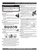
DCA-70USJ — GENERATOR CONTROL PANEL Figure 6. Generator Control Panel The definitions below describe the controls and functions of Located behind the generator control panel is the Generator Control Box. This box contains some of the necessary the DCA-70USJ Generator Control Panel (Figure 6). 1. Main Circuit Breaker – This three-pole, 175A main electronic components required to make the generator breaker is provided to protect the the U,V, and W Output function. 2. 3. 4. 5. 6. 7.
DCA-70USJ — ENGINE OPERATING PANEL Figure 7. Engine Operating Panel PAGE 22 — DCA-70USJ — OPERATION AND PARTS MANUAL — REV.
DCA-70USJ — ENGINE OPERATING PANEL The definitions below describe the controls and functions of During cranking cycle , The MPEC will attempt to crank the the DCA-70USJ Engine Operating Panel (Figure 7). engine for 10 seconds before disengaging. If the engine does 1. Panel Light – Normally used in dark areas or at night not engage (start) by the third attempt, the engine will be time. When activated, panel lights will illuminate.
DCA-70USJ — OUTPUT TERMINAL PANEL FAMILIARIZATION Output Terminal Panel The Output Terminal Panel (Figure 8) shown below is located on the right-hand side (left from control panel) of the generator. Lift up on the cover to gain access to receptacles and terminal lugs.
DCA-70USJ — OUTPUT TERMINAL PANEL FAMILIARIZATION 120 VAC GFCI Receptacles There are two 120 VAC, 20 amp GFCI (Duplex Nema 5-20R) recepacles provided on the output terminal panel. These receptacles can be accessed in any voltage selector switch position. Each receptacle is protected by a 20 amp circuit breaker. These breakers are located directly above the GFCI receptacles.
DCA-70USJ — OUTPUT TERMINAL PANEL FAMILIARIZATION Connecting Loads Blower Fan Loads can be connected to the generator by the Ouput Terminal Lugs or the convienience receptacles. (See Figure 13). Make sure to read the operation manual before attempting to connect a load to the generator. To protect the output terminals from overload, a 3-pole, 175A main circuit breaker is provided. Make sure to switch ALL circuit breakers to the OFF position prior to starting the engine.
DCA-70USJ — LOAD APPLICATION Single Phase Load Three Phase Load Always be sure to check the nameplate on the generator and equipment to insure the wattage, amperage, frequency, and voltage requirements are satisfactorily supplied by the generator for operating the equipment. When calculating the power requirements for 3-phase power use the following equation: Generally, the wattage listed on the nameplate of the equipment is its rated output.
DCA-70USJ — GENERATOR OUTPUTS Voltage Selector Switch Generator Amperage The voltage selector switch (Figure 16) is located above Table 7 describes the generator’s current output capability the output terminal panel’s Hard Wire Hook-up Panel. It for both 1Ø-phase and 3Ø phase applications. has been provided for ease of voltage selection. Table 7. Generator Ampere Ratings DCA-8USJ kW kVA 120V 208V 240V Single Phase 40 N/A 166.7A x 2 N/A 1 6 6 .
DCA-70USJ — GAUGE READING How to Read the Output Terminal Gauges. The gauges and selector switches on the control panel DO NOT effect the generator output. They are provided to help observe how much power is being supplied at the Output terminals lugs. Before taking a reading off either gauge, set the Voltage Selector Switch (Figure 17) to the position which produces the required voltage (For example, for 3Ø 240V, choose the center 3Ø 240/ 139V position on the voltage selector switch.
DCA-70USJ — OUTPUT TERMINAL PANEL CONNECTIONS UVWO Terminal Output Voltages Various output voltages can be obtained using the Output Terminal Lugs.. The voltages at the terminals are dependent on the position of the Voltage Selector Switch and the adjustment of the Voltage Regulator Control Knob. Remember the voltage selector switch determines the range of the output voltage. The voltage regulator (VR) allows the user to increase or decrease the selected voltage.
DCA-70USJ — OUTPUT TERMINAL PANEL CONNECTIONS 1Ø 240V/120V Output Terminal Lug Voltages 3Ø 480/277 Output Terminal Lug Voltages 1. Place the voltage selector switch in the 3Ø 480/277 1. Place the voltage selector switch in the 1Ø 240/120 position as shown in Figure 27. position as shown in Figure 29. Figure 27. Voltage Selector Switch 480/277V Three-Phase Position Figure 29. Voltage Selector Switch 240/120V Single-Phase Position 2. Connect the load wires to the Output Terminal Lugs as 2.
DCA-70USJ — PRE-SETUP Fuel Check Circuit Breakers To protect the generator from an overload, a 3-pole, 175 amp, main circuit breaker is provided to protect the U,V, and W Output Terminals from overload. In addition two single-pole, 20 amp GFCI circuit breakers are provided to protect the GFCI receptacles from overload. Three 50 amp load circuit breakers have also been provided to protect the auxiliary receptacles from overload.
DCA-70USJ — PRE-SETUP Refueling Procedure: 3. WARNING - RESPIRATORY HAZARDS Open cabinet doors on the “right side” of the generator (from generator control panel position). Remove fuel cap and fill tank (Figure 34). Diesel fuel and its vapors are dangerous to your health and the surrounding environment. Avoid skin contact and/or inhaling fumes. 1. Level Tanks – Make sure fuel cells are level with the ground.
DCA-70USJ — PRE-SETUP Coolant (John Deere Antifreeze/Summer Coolant/Water) John Deere recommends John Deere Antifreeze/Summer Coolant for use in thier engines, which can be purchased in concentrate (and mixed with 50% demineralized water) or pre-diluted. See the John Deere Engine Owner's Manual for further details. Cleaning the Radiator The engine may overheat if the radiator fins become overloaded with dust or debris. Periodically clean the radiator fins with compressed air.
DCA-70USJ — PRE-SETUP Battery When connecting battery do the following: This unit is of negative ground DO NOT connect in reverse. 1. NEVER connect the battery cables to the battery terminals when the MPEC Control Switch is in either Always maintain battery fluid level between the specified marks. Battery life will be shortened, if the fluid level are not the MANUAL position. ALWAYS make sure that the MPEC Control Switch is in the OFF/RESET position when properly maintained.
DCA-70USJ — GENERATOR START-UP PROCEDURE (MANUAL) Before Starting 4. Close all engine enclosure doors (Figure 40). CAUTION - LETHAL EXHAUST HAZARD The engine's exhaust contains harmful emissions. ALWAYS have adequate ventilation when operating. Direct exhaust away from nearby personnel. WARNING - STARTING THE GENERATOR NEVER! manually start the engine with the main, GFCI or auxiliary circuit breakers in the ON (closed) position. Figure 40. Engine Enclosure Doors 1. Place the main, G.F.C.I., and aux.
DCA-70USJ — GENERATOR START-UP PROCEDURE (MANUAL) Starting (Manual) 8. Place the MPEC Control Switch in the MANUAL position to start the engine (Figure 42). Figure 42. MPEC Control Switch (Manual Position) In cold weather conditions, placing the MPEC Control Switch in the MANUAL position will preheat and start the engine AUTOMATICALLY. The Preheat Lamp (Figure 43) will turn off when the engine has started. 9.
DCA-70USJ — GENERATOR START-UP PROCEDURE (MANUAL) 12. The engine oil pressure gauge (Figure 49) will indicate the oil pressure (kg/ cm2) of the engine. Under normal operating conditions the oil pressure is approximately 35~65 PSI. Figure 49. Oil Pressure Gauge 15. Place the main, GFCI, and aux. circuit breakers in the ON position (Figure 52). 13. The coolant temperature gauge (Figure 50) will indicate the coolant temperature.
DCA-70USJ — GENERATOR START-UP PROCEDURE (AUTO MODE) Starting (Auto Mode) 1. Perform steps 1 through 5 in the Before Starting section as outlined in the Manual Starting Procedure. DANGER - ELECTRICAL SYSTEM HAZARDS Before connecting this generator to any building’s electrical system, a licensed electrician must install an isolation (transfer) switch. Serious damage to the building’s electrical system may occur without this transfer switch.
DCA-70USJ — GENERATOR SHUT-DOWN PROCEDURE WARNING - SHUTTING DOWN THE GENERATOR NEVER stop the engine suddenly except in an emergency. DO NOT use the emergency stop switch a as method of shutting down the generator. This switch is ONLY to be used in the event of an emergency. Emergency Shutdown Procedure 1. To shut-down the engine in the event of an emergency, switch the MAIN, GFCI and LOAD (Figure 39) circuit breakers to OFF position. 2.
DCA-70USJ — MAINTENANCE 10 Hrs DAILY TABLE 13.
DCA-70USJ — MAINTENANCE Air Removal If air enters the fuel injection system of a diesel engine, starting becomes impossible. After running out of fuel, or after disassembling the fuel system, bleed the system according to the following procedure. See the John Deere Engine Manual for details. Check Oil Level Check the crankcase oil level prior to each use, or when the fuel tank is filled. Insufficient oil may cause severe damage to the engine. Make sure the generator is level.
DCA-70USJ — MAINTENANCE Jacket Water Heater and Internal Battery Charger 120 VAC Input Receptacles (OPTIONAL) This generator can be optionally equipped with two 120 VAC, 20 amp input receptacles located on the output terminal panel. The purpose of these receptacles is to provide power via commercial power to the jacket water heater and internal battery charger. These receptacles will ONLY function when commercial power has been supplied to them (Figure 56).
DCA-70USJ — TRAILER MAINTENANCE 8. Tire Size - Indicates the diameter of the tire in inches (10,12,14, etc.), and the width in millimeters This section is intended to provide the user with generic (175,185,205, etc.). The tire diameter must match the trailer service and maintenance information. The service and diameter of the tire rim. maintenance guidelines referenced in this section refer to a wide range of trailers. 9. Tire Ply - The tire ply (layers) number is rated in letters; 2-ply,4-ply,6-ply, etc.
DCA-70USJ — TRAILER MAINTENANCE Brakes Trailer brakes should be inspected the first 200 miles of operation. This will allow the brake shoes and drums to seat properly. After the first 200 mile interval, inspect the brakes every 3,000 miles. If driving over rough terrain, inspect the brakes more frequently. Figure 57 displays the major hydraulic surge brake components that will require inspection and maintenance.
DCA-70USJ — TRAILER MAINTENANCE Tires/Wheels/Lug Nuts Tires and wheels are a very important and critical components of the trailer. When specifying or replacing the trailer wheels it is important the wheels, tires, and axle are properly matched. CAUTION - EYESIGHT HAZARD Suspension The leaf suspension springs and associated components (Figure 58) should be visually inspected every 6,000 miles for signs of excessive wear, elongation of bolt holes, and loosening of fasteners.
DCA-70USJ — TRAILER MAINTENANCE Lug Nut Torque Requirements It is extremely important to apply and maintain proper wheel mounting torque on the trailer. Be sure to use only the fasteners matched to the cone angle of the wheel. Proper procedure for attachment of the wheels is as follows: 1. Start all wheel lug nuts by hand. 2. Torque all lug nuts in sequence (see Figure 59). DO NOT torque the wheel lug nuts all the way down. Tighten each lug nut in 3 separate passes as defined by Table 17. 3.
DCA-70USJ — TRAILER WIRING DIAGRAM Figure 60. Trailer/Towing Vehicle Wiring Diagram PAGE 48 — DCA-70USJ — OPERATION AND PARTS MANUAL — REV.
DCA-70USJ — GENERATOR WIRING DIAGRAM Figure 61. Generator Wiring Diagram 1 DCA-70USJ — OPERATION AND PARTS MANUAL — REV.
DCA-70USJ — ENGINE WIRING DIAGRAM Figure 62. Engine Wiring Diagram PAGE 50 — DCA-70USJ — OPERATION AND PARTS MANUAL — REV.
DCA-70USJ — TROUBLESHOOTING (GENERATOR) Practically all breakdowns can be prevented by proper handling and maintenance inspections, but in the event of a breakdown, use Table 18 shown below for diagnosis of the Generator. If the problem cannot be remedied, consult our company's business office or service plant. TABLE 18.
DCA-70USJ — TROUBLESHOOTING (ENGINE CONTROLLER) Practically all breakdowns can be prevented by proper handling and maintenance inspections, but in the event of a breakdown, use Table 19 (Engine Controller Troubleshooting) as a basic guideline for troubleshooting the Microprocessor Engine Controller unit (MPEC). If the problem cannot be remedied, consult our company's business office or service plant. TABLE 19. ENGINE CONTROLLER TROUBLESHOOTING (MPEC) SYMPTOM POSSIBLE PROBLEM Low oil pressure light is on.
NOTE PAGE 1 DCA-70USJ — OPERATION AND PARTS MANUAL — REV.
EXPLANATION OF CODE IN REMARKS COLUMN How to read the marks and remarks used in this parts book. Items Found In the “Remarks” Column Serial Numbers-Where indicated, this indicates a serial number range (inclusive) where a particular part is used. Model Number-Where indicated, this shows that the corresponding part is utilized only with this specific model number or model number variant.
DCA-70USJ — SUGGESTED SPARE PARTS DCA-70USJ ULTRA-SILENT GENRATOR W/JOHN DEERE 4045TF275 DIESEL ENGINE 1 TO 3 UNITS Qty. P/N Description 5 ......... 0602041292 ........ FILTER, OIL 5 ......... 0602042594 ........ FILTER, FUEL, PRIMARY 5 ......... 0602042595 ........ FILTER, FUEL, FINAL 3 ......... 0602046377 ........ ELEMENT, AIR 1 ......... 0602011493 ........ BELT, FAN 1 ......... 0605505070 ........ CAP. FUEL TANK 1 ......... 0602122272 ........ UNIT, OIL PRESSURE 1 ......... 0602123261 ........
DCA-70USJ — GENERATOR ASSY. GENERATOR ASSY. PAGE 56 — DCA-70USJ — OPERATION AND PARTS MANUAL — REV.
DCA-70USJ — GENERATOR ASSY. GENERATOR ASSY. NO. PART NO.
DCA-70USJ — CONTROL BOX ASSY. CONTROL BOX ASSY. PAGE 58 — DCA-70USJ — OPERATION AND PARTS MANUAL — REV.
DCA-70USJ — CONTROL BOX ASSY. CONTROL BOX ASSY. NO. PART NO. 1 M2213000702 2 0330000180 3 0601808824 4 0021005080 5 0601823863 6 0027104016 7 0601820671 8 0027105016 9 0601806139 10 0027106016 11 0601820845 12 0601820846 13 0027104016 13A 0207004000 14 M3213500013 15 0016906016 16 M3270100104 16A * 17 18 19 20 21 22 23 24 24A 25 TBD M3276600004 M2213600503 0330000330 0027104010 0016906016 M2213600404 0016906016 0016906016 0040506000 M2223000403 PART NAME QTY.
DCA-70USJ — CONTROL BOX ASSY. CONTROL BOX ASSY. PAGE 60 — DCA-70USJ — OPERATION AND PARTS MANUAL — REV.
DCA-70USJ — CONTROL BOX ASSY. CONTROL BOX ASSY. NO. PART NO.
DCA-70USJ — ENGINE & RADIATOR ASSY. ENGINE & RADIATOR ASSY. PAGE 62 — DCA-70USJ — OPERATION AND PARTS MANUAL — REV.
DCA-70USJ — ENGINE & RADIATOR ASSY. ENGINE & RADIATOR ASSY. NO. PART NO.
DCA-70USJ — ENGINE & RADIATOR ASSY. ENGINE & RADIATOR ASSY. PAGE 64 — DCA-70USJ — OPERATION AND PARTS MANUAL — REV.
DCA-70USJ — ENGINE & RADIATOR ASSY. ENGINE & RADIATOR ASSY. NO. PART NO.
DCA-70USJ — OUTPUT TERMINAL ASSY. OUTPUT TERMINAL ASSY. PAGE 66 — DCA-70USJ — OPERATION AND PARTS MANUAL — REV.
DCA-70USJ — OUTPUT TERMINAL ASSY. OUTPUT TERMINAL ASSY. NO. PART NO.
DCA-70USJ — BATTERY ASSY. BATTERY ASSY. PAGE 68 — DCA-70USJ — OPERATION AND PARTS MANUAL — REV.
DCA-70USJ — BATTERY ASSY. BATTERY ASSY. NO. PART NO. 1 0602220187 2 M9310500014 3 M9103000304 4 0602220920 5 M2346900204 6 M2346900304 7 8 0017112025 9 0040520000 10 0040512000 PART NAME QTY. REMARKS BATTERY ............................................................1 ........ 627MFD BATTERY SHEET 1 BATTERY BAND 1 BATTERY BOLT SET 2 BATTERY CABLE 1 BATTERY CABLE 1 CABLE ................................................................1 ........
DCA-70USJ — MUFFLER ASSY. MUFFLER ASSY. PAGE 70 — DCA-70USJ — OPERATION AND PARTS MANUAL — REV.
DCA-70USJ — MUFFLER ASSY. MUFFLER ASSY. NO. PART NO. 1 M2330100803 2 0017112030 3 M2333000703 4 M2333200204 5 0017110040 6 M3333200204 7 0017110035 8 M2333000603 9 0017110050 10 0602325066 PART NAME MUFFLER BOLT, HEX HEAD EXHAUST PIPE GASKET BOLT, HEX HEAD GASKET BOLT, HEX HEAD EXHAUST PIPE BOLT, HEX HEAD CLAMP QTY. 1 4 1 1 4 1 4 1 4 1 REMARKS 1 DCA-70USJ — OPERATION AND PARTS MANUAL — REV.
DCA-70USJ — FUEL TANK ASSY. FUEL TANK ASSY. 7 PAGE 72 — DCA-70USJ — OPERATION AND PARTS MANUAL — REV.
DCA-70USJ — FUEL TANK ASSY. FUEL TANK ASSY. NO. PART NO. 1 M2363000902 1-1 0605505070 1-2 0605501073 1-3 0605516090 2 M2363200404 3 M9310500104 4 0016908020 5 0016908055 5A 0207008000 6 0191302040 7 0605515109 8 0191301000 9 0191301200 10 0605515109 11 0605515189 12 0602042601 13 0222101000 PART NAME QTY.
DCA-70USJ — ENCLOSURE #1 ASSY. ENCLOSURE #1 ASSY. PAGE 74 — DCA-70USJ — OPERATION AND PARTS MANUAL — REV.
DCA-70USJ — ENCLOSURE #1 ASSY. ENCLOSURE #1 ASSY. NO. PART NO.
DCA-70USJ — ENCLOSURE #1 ASSY. ENCLOSURE #1 ASSY. PAGE 76 — DCA-70USJ — OPERATION AND PARTS MANUAL — REV.
DCA-70USJ — ENCLOSURE #1 ASSY. ENCLOSURE #1 ASSY. NO. PART NO.
DCA-70USJ — ENCLOSURE #2 ASSY. ENCLOSURE #2 ASSY. ADD THE FOLLOWING DIGITS AFTER THE PART NUMBER WHEN ORDERING ANY PAINTED PANEL TO INDICATE COLOR OF UNIT: 1-ORANGE 2-WHITE 3-SPECTRUM GREY 4-SUNBELT GREEN 5-BLACK 6-CATERPILLAR YELLOW 7-CATO GOLD 8-RED THE SERIAL NUMBER MAY BE REQUIRED. PAGE 78 — DCA-70USJ — OPERATION AND PARTS MANUAL — REV.
DCA-70USJ — ENCLOSURE #2 ASSY. ENCLOSURE #2 ASSY. NO. PART NO.
DCA-70USJ — ENCLOSURE #3 ASSY. ENCLOSURE #3 ASSY. PAGE 80 — DCA-70USJ — OPERATION AND PARTS MANUAL — REV.
DCA-70USJ — ENCLOSURE #3 ASSY. ENCLOSURE #3 ASSY. NO. PART NO.
DCA-70USJ — NAME PLATE ASSY. NAME PLATE ASSY. PAGE 82 — DCA-70USJ — OPERATION AND PARTS MANUAL — REV.
DCA-70USJ — NAME PLATE ASSY. NAME PLATE ASSY. NO. PART NO.
Effective: October 1, 2002 PAYMENT TERMS TERMS AND CONDITIONS OF SALE — PARTS 5. Parts must be in new and resalable condition, in the original Multiquip package (if any), and with Multiquip part numbers clearly marked. 6. The following items are not returnable: Terms of payment for parts are net 10 days. FREIGHT POLICY All parts orders will be shipped collect or prepaid with the charges added to the invoice. All shipments are F.O.B. point of origin.
NOTE PAGE 1 DCA-70USJ — OPERATION AND PARTS MANUAL — REV.
PARTS AND OPERATION MANUAL OPERATION AND PARTS MANUAL HERE'S HOW TO GET HELP PLEASE HAVE THE MODEL AND SERIAL NUMBER ON-HAND WHEN CALLING MQ POWER CORPORATE OFFICE 18910 Wilmington Ave. 800-421-1244 FAX: 310-632-2656 Carson, CA 90746 Email: mqpower@multiquip.com Internet: www.mqpower.