Operation and Parts Manual MODEL gac2.2h portable generator (HONDA GX160 GASOLINE ENGINE) Revision #1 (03/31/10) To find the latest revision of this publication, visit our website at: www.multiquip.com THIS MANUAL MUST ACCOMPANY THE EQUIPMENT AT ALL TIMES.
Table of Contents GAC2.2H Portable 60 Hz Generator Table Of Contents..................................................... 2 Parts Ordering Procedures....................................... 3 Safety Information................................................. 4-8 Specifications (Generator)...................................... 10 Specifications (Engine)........................................... 11 Dimensions............................................................. 12 Installation......................
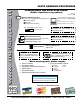
www.multiquip.com parts ordering procedures Ordering parts has never been easier! choose from three easy options: Order via internet (dealers Only): Best deal! Effective: January 1st, 2006 If you have an MQ Account, to obtain a Username and Password, E-mail us at: parts@multiquip. com. Order parts on-line using Multiquip’s SmartEquip website! ■ View Parts Diagrams ■ Order Parts ■ Print Specification Information To obtain an MQ Account, contact your District Sales Manager for more information.
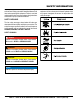
Safety Information Do not operate or service the equipment before reading the entire manual. Safety precautions should be followed at all times when operating this equipment. Failure to read and understand the safety messages and operating instructions could result in injury to yourself and others. Potential hazards associated with the operation of this equipment will be referenced with hazard symbols which may appear throughout this manual in conjunction with safety messages.
Safety Information geNeRal saFeTY cauTiON NeveR operate this equipment without proper protective clothing, shatterproof glasses, respiratory protection, hearing protection, steel-toed boots and other protective devices required by the job or city and state regulations. NeveR operate this equipment when not feeling well due to fatigue, illness or when under medication. NeveR operate this equipment under the influence of drugs or alcohol.
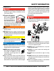
Safety Information eNgiNe saFeTY daNgeR The engine fuel exhaust gases contain poisonous carbon monoxide. This gas is colorless and odorless, and can cause death if inhaled. The engine of this equipment requires an adequate free flow of cooling air. NeveR operate this equipment in any enclosed or narrow area where free flow of the air is restricted. If the air flow is restricted it will cause injury to people and property and serious damage to the equipment or engine.
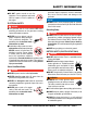
Safety Information NeveR use fuel as a cleaning agent. dO NOT smoke around or near the equipment. Fire or explosion could result from fuel vapors or if fuel is spilled on a hot engine. elecTRical saFeTY daNgeR Make sure power cables are securely connected to the generator’s output receptacles. Incorrect connections may cause electrical shock and damage to the generator. NOTICE alWaYs make certain that proper power or extension cord has been selected for the job.
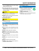
Safety Information If the battery liquid (dilute sulfuric acid) comes into contact with clothing or skin, rinse skin or clothing immediately with plenty of water. eNviRONmeNTal saFeTY If the battery liquid (dilute sulfuric acid) comes into contact with eyes, rinse eyes immediately with plenty of water and contact the nearest doctor or hospital to seek medical attention. Dispose of hazardous waste properly. Examples of potentially hazardous waste are used motor oil, fuel and fuel filters.
NOTES gac2.2H 60 hz GENERATOR • operation and parts manual — rev.
SPECIFICATIONS (gENERATOR) Table 1. Specifications (Generators) Model Type Excitation Speed Cooling System Continuous Power Output AC Generator 60 Hz AC Power Sourc Max Power Output Rated Voltage Current Max/Continuous (120V) Phase Frequency Power Factor Dimensions (L x W x H) Dry Net Weight GAC 2.2H Brushless Revolving Field Type Solid State, Statically Excited System 3,600 RPM Self-Ventilation 1.8 kW 2.2 kW 120V 15 amps Single Phase (2 wire) 60 Hz 1 19.68 x 16.14 X 18.30 in. (500 X 410 X 465 mm) 106 lbs.
SPECIFICATIONS (engine) Engine Dimensions (L x W x H) Dry Net Weight Table 2. Specifications (Engine) HONDA GX160K1EMA2 Model HONDA GX160U1EMAN 4 stroke, Single Cylinder, OHV, Type Gasoline Engine 2.68 in. X 1.77 in. Bore X Stroke (68 mm x 45 mm.) Displacement 9.95 cu-in (163 cm3) Max Output 5.5 H.P./3600 R.P.M. Fuel Unleaded Automobile Gasoline Fuel Capacity 3.16 gallons (12 liters) Lube Oil Capacity .63 quarts (0.
dimensions GAC-2.2H 120V 15A V 120 NEUTRAL BONDED TO FRAME NEUTRE MIS A LA MASSE A LA CARCASSE DU MOTEUR POWERED by Honda Engines AC VOLTMETER VOLTOMETRE CA OFF 211052 GR PRISE DE TERRE AC CIRCUIT BREAKER INTERRUPTEUR DE COURANT PRINCIPAL A21210011 18.30 IN. (465 MM) 19.7 IN. (500 MM) 16.1 IN. (410 MM) Figure 1. Dimensions page 12 — gac2.2H 60 hz gENERATOR• operation and parts manual — rev.
note gac2.2H 60 hz GENERATOR • operation and parts manual — rev.
installation Connecting the Ground The nut and ground terminal on the generators should always be used to connect the generators to a suitable ground. The ground cable should be #8 size wire minimum. At the generator, connect the terminal of the ground cable between the lock washer and the nut (Figure 2) and tighten the nut fully. Connect the other end of the ground cable to a suitable earth ground (ground rod). GAC-2.
installation Outdoor Installation Generator Grounding If possible install the generator in a area that is free of debris, bystanders, and overhead obstructions. Make sure the generator is on secure level ground so that it cannot slide or shift around. To guard against electrical shock and possible damage to the equipment, it is important to provide a good EARTH ground. The installation site must be relatively free from moisture and dust.
general information GAC2.2H FAMILIARIZATION Generator The Multiquip GAC2.2H generator has been designed as a portable dual purpose power source for 60 Hz (single phase) lighting facilities, power tools, submersible pumps and other industrial and construction machinery. DANGER Before connecting this generator to any building’s electrical system, a licensed electrician must install an isolation (transfer) switch. Serious injury or death may result without this transfer switch.
components (generator) 1 GAC-2.2H 2 120V 15A V 120 NEUTRAL BONDED TO FRAME NEUTRE MIS A LA MASSE A LA CARCASSE DU MOTEUR POWERED by Honda Engines AC VOLTMETER VOLTOMETRE CA OFF 211052 GR PRISE DE TERRE AC CIRCUIT BREAKER INTERRUPTEUR DE COURANT PRINCIPAL 3 A21210011 7 6 5 4 Figure 3. Generator Components 1. GFCI Duplex Receptacle – NEMA 5-15R, GFCI receptacle will provide 120V @ 15 amps. 2. AC-Voltmeter – Indicates (with a mark) the rated 60 Hz (single-phase) output voltage.
components (generator) Figure 4. Generator Components (Continued) 8. Muffler/Heat Shield – Used to reduce noise and emissions. NEVER touch this heat shield when the generator/welder is in use. Always allow time for engine to cool before servicing. 9. Air Cleaner – Prevents dirt and other debris from entering the fuel system. Remove wing-nut on top of air filter cannister to gain access to filter element. NEVER run the engine without an air cleaner. 10. Spark Plug – Provides spark to the ignition system.
INSPECTION/SETUP General Inspection Prior to Operation Extension Cable Ground Power Tools When electric power is to be provided to various tools or loads at some distance from the generator, extension cords are normally used. Cables should be sized to allow for distance in length and amperage so that the voltage drop between the generators and point of use (load) is held to a minimum. Use the cable selection chart (Table 3) as a guide for selecting proper cable size.
INSPECTION/SETUP Before Starting 1. Read safety instructions at the beginning of manual. 2. Clean the generator, removing dirt and dust, particularly the engine cooling air inlet, carburetor and air cleaner. 3. Check the air filter for dirt and dust. If air filter is dirty, replace air filter with a new one as required. 4. Check carburetor for external dirt and dust. Clean with dry compressed air. Figure 7. Engine Oil Dipstick(Oil Level) 5. Check fastening nuts and bolts for tightness Engine Oil Check 1.
operation This section is intended to assist the operator with the initial start-up of the portable generator. It is extremely important that this section be read carefully before attempting to use the generators in the field. Before Starting the Engine 3. Place the choke lever (Figure 11) in the OPEN position if starting a warm engine or the temperature is warm. 4. Place the engine ON/OFF switch (Figure 12) in the ON position. 1.
operation 8. Place main circuit breaker (Figure 14) in the ON position. 2. Let the engine run at idle with no load for 2-3 minutes. 3. Place the engine ON/OFF switch (Figure 17) in the OFF position. Figure 14. Main Circuit Breaker (ON) 9. Read the voltmeter on the front panel of the generator (Figure 15) and verify that 120 VAC is present at the GFCI duplex receptacle. For additional verification of voltage, an external voltmeter can be used to measure the output voltage as shown in Figure 15.
preparation for long term storage Generators Storage For storage of the generating set for over 30 days, the following is required: Drain the fuel tank completely, or add STA-BIL to the fuel. Run the engine until the gasoline in the carburetor is completely consumed. Completely drain the oil from the crankcase and refill with fresh oil. Remove the spark plug, pour 2 or 3 cc of SAE 30 oil into the cylinder and crank slowly to distribute the oil.
maintenance Use Table 5 as a general maintenance guideline when servicing your engine. For more detail engine maintenance information, refer to the engine owner's manual supplied with your engine. Table 5.
maintenance Maintenance Perform the scheduled maintenance procedures as defined by Table 5: Daily Thoroughly remove dirt and oil from the engine and control area. Clean or replace the air cleaner elements as necessary. Check and retighten all fasteners as necessary. Weekly Remove the fuel filter cap and clean the inside of the fuel tank. Remove or clean the filter at the bottom of the tank. Remove and clean the spark plug (Figure 19), then adjust the spark gap to 0.024 ~0.028 inch (0.6~0.7 mm).
generator wiring diagram SYMBOL PART NAME Ar Armature Winding Fg-PN Field Winding EXW1~2 Excitation Winding V Re Wiring Color Code Symbol Color Symbol B BLACK R Color RED L BLUE W WHITE AC Voltmeter (120/240) BR BROWN Y YELLOW Rectifier G GREEN LB LIGHT BLUE CON Receptacle 5-15R GR GRAY LG LIGHT GREEN CB UPM-1 15A V VIOLET O ORANGE CB1 CP-31E/15N 15A P PINK Figure 22. Generator Wiring Diagram page 26 — gac2.2H 60 hz gENERATOR• operation and parts manual — rev.
troubleshooting Table 6. Engine Troubleshooting Symptom Difficult to start. Fuel is available but no SPARK at spark plug. Difficult to start. Fuel is available and SPARK is present at the spark plug. Difficult to start. Fuel is available, SPARK is present at the spark plug and compression is normal. Difficult to start. Fuel is available, SPARK is present at the spark plug and compression is low. No fuel present at carburetor. Weak in power. Compression is proper and does not misfire.
troubleshooting Table 6. Engine Troubleshooting (Continued) Symptom Possible Cause Solution Weak in power. Compression is proper but misfires. Water in fuel system? Flush fuel system and replace with correct type of fuel. Dirty spark plug? Clean or replace spark plug Ignition coil defective? Replace ignition coil. Spark plug heat value improper? Replace with correct type of spark plug. Incorrect type of fuel? Replace with correct type of fuel. Cooling fins dirty? Clean cooling fins.
troubleshooting Symptom Low voltage Low voltage. Engine speed normal 3650 RPM (unloaded), 2500 RPM (idle) Table 7. Generator Troubleshooting Possible Problem Solution Engine speed too low? Raise engine speed to rated RPM. AC voltmeter not working? Replace Ac voltmeter. Control box internal wiring Check control box wiring. malfunction? Check red and green ignition wires. Defective ignition coil? Replace ignition wires if necessary. Rotor winding malfunction? Check or replace rotor.
Explanation of Code in Remarks Column The following section explains the different symbols and remarks used in the Parts section of this manual. Use the help numbers found on the back page of the manual if there are any questions. NOTICE The contents and part numbers listed in the parts section are subject to change without notice. Multiquip does not guarantee the availability of the parts listed. sample paRTs lisT NO. 1 2% 2% 3 4 paRT NO. paRT Name QTY. RemaRKs 12345 BOLT......................1 .....
Suggested Spare Parts gaC2.2H portable 60 hZ generator with honda GX160k1eMA2/ GX160U1EMan gasoline engineS 1 to 3 units Qty. P/N Description 1............0810106004...........CAP FUEL TANK 1............0810107103...........FILTER FUEL 4............7935419204...........RUBBER SUSPENSION 4............7935419304...........RUBBER SUSPENSION 3............9807956846...........SPARK PLUG 1♦..........34150ZH7003........SWITCH ASSY., OIL ALERT 1◊ .........34150ZH7013........SWITCH ASSY., OIL ALERT 2............
nameplate and decals S/N 5560983 AND BELOW 3 2200 WARNING/ATTENTION 8 Only operate machine in well ventilated areas. Do not inhale exhaust gases. N’utilizez l’equipment que dans des endroits bien aérés. CAUTION Ne respirez paz les gas d’échappement. Do not use in rain or snow. 1 ATTENTION Ne pas utiliser en cas de pluie ou neige. Dangerous Gas/Gas dangereux 2 A63210090A Only qualified personnel should install, use, or service this equipment.
nameplate and decals NO. PART NO. 1 A3552000004A 2 A6552000404A 3 A6532100904A 4 A6532101004A 5 A5552000804 6 A5552000704A 7 A9508200004 8 A1562000803 9 A2512100112 10 A3532100304A 11 A9511100204 12 A9504000104 13 A9504000204 PART NAME QTY. REMARKS DECAL; CAUTION, RAIN SNOW........................1................A35200000A DECAL; CAUTION, HOT PARTS........................1................A65300040A DECAL; WARNING, EXHAUST GASES.............1................A63210090A DECAL; DANGER, ELECTROCUTION.
generator assy. page 34 — gac2.2H 60 hz gENERATOR• operation and parts manual — rev.
generator assy. NO. 1 1-1 1-2 1-3 2 3 4 5 6 7 8 9 10 11 12 13 14 15 16 17 18 19 20 PART NO. 7931000203 7681080003 0601823213 0601822637 0603000040 7681017104 0801086004 0040008000 A2136000503 7931315002 7931315102 7875021523 7681331003 7681344204 0040006000 0041206000 7871329514 0601851760 0017408020 7935420104 0021806010 7935420004 0207206000 0017108020 PART NAME ROTOR ASSY. FIELD COIL RECTIFIER SURGE ABSSORBER BEARING SET BOLT, ROTOR SET WASHER, BEARING WASHER, LOCK ARMATURE ASSY.
CONTROL BOX assy. page 36 — gac2.2H 60 hz gENERATOR• operation and parts manual — rev.
CONTROL BOX assy. NO. 1 2 3 4 5 6 7 8 9 10 11 12 12A 12B 12C 13 13A 14 14A 14B 14C 15 15A 16 17 17A 18 19 PART NO. A2215000103 0301850215 0601823204 0027103020 0017106015 A2225000503 0601806867 0038303000 0601807462 0027104010 A3262800104 0601815147 0040005000 0031005000 0038305000 0010005025 0038305000 0010005040 0040505000 0031005000 0038305000 0017105010 0040505000 0601812590 0027104016 0038304000 A2225200004 0027103010 PART NAME CONTROL BOX GROMMET RECTIFIER MACHINE SCREW HEX.
PIPE FRAME assy. page 38 — gac2.2H 60 hz gENERATOR• operation and parts manual — rev.
PIPE FRAME assy. NO. PART NO. PART NAME QTY. REMARKS 1 A2418000202 PIPE FRAME 1 2 0801886104 WASHER 2 3 7935419204 RUBBER SUSPENSION 2 4 7935419304 RUBBER SUSPENSION 2 5 0207208000 HEX NUT 8 6 7935510102 FUEL TANK 1 7 0810106004 CAP FUEL TANK 1 8 0810107103 FUEL FILTER 1 9 0602125034 FUEL GAUGE 1 10 0605510065 FUEL STRAINER................................................1................INCLUDES ITEMS W/# . ............................................................................................
HONDA GX160K1EMA2/U1EMAN engine — cyl. hd assy. page 40 — gac2.2H 60 hz gENERATOR• operation and parts manual — rev.
HONDA GX160K1EMA2/U1EMAN engine — cyl. hd assy. NO. 1♦ 1◊ 2# 3# 4# 5 6♦ 6◊ 7 8♦ 8◊ 9 10 11 12 13 14 14 PART NO. 12210ZH8020 12210ZH8415 12204ZE1306 12205ZE1315 12216ZE5300 12251ZF1800 12310ZE1010 12310ZE1020 12391ZE1000 15721732000 15721883030 90013883000 90043ZB2003 90047ZE1000 9430110160 957230806000 9807956846 9807956855 PART NAME QTY. REMARKS HEAD COMP., CYLINDER..................................1................INCLUDES ITEMS W/# HEAD COMP., CYLINDER..................................1................
HONDA GX160K1EMA2/U1EMAN engine — cyl. barrel assy. page 42 — gac2.2H 60 hz gENERATOR• operation and parts manual — rev.
HONDA GX160K1EMA2/U1EMAN engine — cyl. barrel assy. NO. PART NO. 2♦ 12000ZH8406 2◊ 12000ZH8426 3♦ 15510ZE1033 3◊ 15510ZE1043 4♦ 16510ZE1000 4♦ 16506ZL0000 4◊ 16506ZL0000 5%♦ 16511ZE1000 6%♦ 16512ZE1000 7%♦ 16513ZE1000 8 16531ZE1000 9 16541ZE1000 12 90131ZE1000 13 90451ZE1000 14 90601ZE1000 15 90602ZE1000 16# 91001ZF1003 17# 91201Z0T801 18 91353671004 19 9405010000 20 9410106800 21 9425108000 22 957010601200 23 06111ZH8405 PART NAME QTY. REMARKS BARREL ASSY, CYLINDER (OIL ALERT)..........1............
HONDA GX160K1EMA2/U1EMAN engine — crankcase cvr. assy. page 44 — gac2.2H 60 hz gENERATOR• operation and parts manual — rev.
HONDA GX160K1EMA2/U1EMAN engine — crankcase cvr. assy. NO. 1 3 4 5 8# 9% 10 11 12% PART NO. 11300ZE1634 11381ZH8801 15600ZE1003 15600ZG4003 15625ZE1003 91201Z0T801 9430108140 957010803200 961006205000 PART NAME QTY. REMARKS COVER ASSY, CRANKCASE.............................1................INCLUDES ITEMS W/% GASKET, CASE COVER 1 CAP ASSY, OIL FILLER......................................1................
HONDA GX160K1EMA2/U1EMAN engine — CRANKSHAFT assy. page 46 — gac2.2H 60 hz gENERATOR• operation and parts manual — rev.
HONDA GX160K1EMA2/U1EMAN engine — CRANKSHAFT assy. NO. 1 PART NO. 13310ZB2000 PART NAME CRANKSHAFT COMP. QTY. 1 REMARKS gac2.2H 60 hz GENERATOR • operation and parts manual — rev.
HONDA GX160K1EMA2/U1EMAN engine — PISTON assy. page 48 — gac2.2H 60 hz gENERATOR• operation and parts manual — rev.
HONDA GX160K1EMA2/U1EMAN engine — PISTON assy. NO. 1♦ 1◊ 1♦ 1◊ 1♦ 1◊ 1♦ 1◊ 2 2 2♦ 2◊ 2♦ 2◊ 3 4 5 6 PART NO. 13010ZF1023 13010Z4K004 13011ZF1023 13011Z4K004 13012ZF1023 13012Z4K004 13013ZF1023 13013Z4K004 13101ZH8010 13102ZH8010 13103ZH8000 13103ZH8010 13102ZH8010 13104ZH8010 13111ZE1000 13200ZE1010 90001ZE1000 90551ZE1000 PART NAME RING SET, PISTON (STD) RING SET, PISTON (STD) RING SET, PISTON (0.25) RING SET, PISTON (0.25) RING SET, PISTON (0.50) RING SET, PISTON (0.50) RING SET, PISTON (0.
HONDA GX160K1EMA2/U1EMAN engine — cAMshaft assy. page 50 — gac2.2H 60 hz gENERATOR• operation and parts manual — rev.
HONDA GX160K1EMA2/U1EMAN engine — cAMshaft assy. NO. 1♦ 1♦ 1◊ 2 3 4 5 6 7 8 9 10 11 12 13 14 15 18♦ PART NO. 14100ZE1812 14100ZL0000 14100ZL0000 14410ZE1010 14431ZE1000 14441ZE1000 14451ZE1013 14568ZE1000 14711ZF1000 14721ZF1000 14751ZF1000 14771ZE1000 14773ZE1000 14781ZE1000 14791ZE1010 90012ZE0010 90206ZE1000 12209ZH8003 PART NAME QTY. REMARKS CAMSHAFT ASSY..............................................1................UP TO S/N 4913229 CAMSHAFT ASSY..............................................1........
HONDA GX160K1EMA2/U1EMAN engine — RECOIL STARTER assy. page 52 — gac2.2H 60 hz gENERATOR• operation and parts manual — rev.
HONDA GX160K1EMA2/U1EMAN engine — RECOIL STARTER assy. NO. 1♦ 1◊ 2 3♦ 3◊ 4♦ 4◊ 5♦ 5◊ 6♦ 6◊ 7 8 9 10 12♦ 12◊ 13 PART NO.
HONDA GX160K1EMA2/U1EMAN engine — FAN COVER assy. page 54 — gac2.2H 60 hz gENERATOR• operation and parts manual — rev.
HONDA GX160K1EMA2/U1EMAN engine — FAN COVER assy. NO. PART NO. 3* 16584883300 4 19610ZE1000ZC 7♦ 19611ZH8820 7♦ 19612ZH8821 7♦ 19612ZH8830 7◊ 19611ZH8820 10♦ 19613ZE1010 10♦ 90601ZH7013 10◊ 90601ZH7013 11 19630ZB2000 12♦ 19640ZB2010 12♦ 19640ZH8R60 12◊ 19640ZH8R60 13♦ 32197ZH8003 14♦ 36100ZE1015 14♦ 36100ZH7003 14◊ 36100ZF6P81 17 90013883000 18 90022888010 19# 93500050350A 19# 93500050400G 21 957010600800 23♦ 34150ZH7003 23◊ 34150ZH7003 24♦ 957010600800 24◊ 957010600800 PART NAME QTY.
HONDA GX160K1EMA2/U1EMAN engine — caRBURETOR assy. page 56 — gac2.2H 60 hz gENERATOR• operation and parts manual — rev.
HONDA GX160K1EMA2/U1EMAN engine — caRBURETOR assy. NO. PART NO. 1#%+ 16010ZB1015 2$ 16011ZE0005 3$ 16013ZE0005 4$♦ 16015ZE0831 4$♦ 16015ZE1811 4$◊ 16015ZE0831 6$ 16016ZH7W01 7 16024ZE1811 8 16028ZE0005 9$ 16044ZE0005 10♦ 16100ZH8E81 10◊ 16100Z4JE81 11$ 16124ZE0005 12$ 16166ZH8E80 13 16211ZE1000 14 16212ZH8800 15 16221ZH8801 16 16269ZE1800 17 16610ZB2000 18< 9430520122 19 99101ZH80700 19 99101ZH80720 19$ 99101ZH80750 20$ 99204ZE00350 PART NAME QTY.
HONDA GX160K1EMA2/U1EMAN engine — AIR CLEANER assy. page 58 — gac2.2H 60 hz gENERATOR• operation and parts manual — rev.
HONDA GX160K1EMA2/U1EMAN engine — AIR CLEANER assy. NO. 1 2♦ 2◊ 3♦ 3◊ 4 5 6 7 8 9 10◊ PART NO. 17211ZB2000 17212ZB2000 17212ZB2800 17220ZB2000 17220ZB2800 17231ZB2000 17239ZB2000 17252ZB2000 90115459770 9405006080 957010601000 17232898000 PART NAME ELEMENT, AIR CLEANER SEPARATOR, AIR CLEANER SEPARATOR, AIR CLEANER CASE COMP., AIR CLEANER CASE COMP., AIR CLEANER COVER AIR CLEANER STAY AIR CLEANER SEAL, AIR CLEANER BOLT, SETTING BOLT, FLANGE, 6MM BOLT, FLANGE, 6X10 GROMMET, AIR CLEANER QTY.
HONDA GX160K1EMA2/U1EMAN engine — MUFFLER assy. page 60 — gac2.2H 60 hz gENERATOR• operation and parts manual — rev.
HONDA GX160K1EMA2/U1EMAN engine — MUFFLER assy. NO. 1 2 3 4 5 6 8 9 PART NO. 18310ZB3C00 18320ZB2000 18325ZH8T90 18329ZB2000 18330ZH8T90 18355898630 18381ZE1800 18381ZH8800 PART NAME MUFFLER COMP. PROTECTOR, MUFFLER OUTER PROTECTOR, MUFFLER INNER SEAL, MUFFLER PROTECTOR PIPE COMP., EX ARRESTER, SPARK GASKET, MUFFLER GASKET, MUFFLER QTY. 1 1 1 2 1 1 1 1 REMARKS gac2.2H 60 hz GENERATOR • operation and parts manual — rev.
HONDA GX160K1EMA2/U1EMAN engine — FLYWHEEL assy. page 62 — gac2.2H 60 hz gENERATOR• operation and parts manual — rev.
HONDA GX160K1EMA2/U1EMAN engine — FLYWHEEL assy. NO. 1 2 3 4 5 PART NO. 13331357000 19511ZE1000 28451ZH8003 31100ZE1811 90201878003 PART NAME KEY, SPECIAL WOOD RUFF, 25X18 FAN, COOLING PULLEY, STARTER FLYWHEEL (LAMP) NUT, SPECIAL, 14MM QTY. 1 1 1 1 1 REMARKS gac2.2H 60 hz GENERATOR • operation and parts manual — rev.
HONDA GX160K1EMA2/U1EMAN engine — IGNITION COIL assy. page 64 — gac2.2H 60 hz gENERATOR• operation and parts manual — rev.
HONDA GX160K1EMA2/U1EMAN engine — IGNITION COIL assy. NO. 1♦ 1◊ 2 4 5 6 7 8 9 10 PART NO. 30500ZE1033 30500ZE1073 30700ZE1013 31510ZE1811 31511ZE1000 31511ZE1000 36101ZE1010 90019883000 90015883000 90121952000 PART NAME COIL ASSY., IGNITION COIL ASSY., IGNITION CAP ASSY., NOISE SUPPRESSOR COIL ASSY., LAMP (12V25W) CLAMPER, CORD GROMMET, CORD CORD, STOP SWITCH (370 MM) BOLT, FLANGE, 5X10 BOLT, FLANGE, 6X28 BOLT, FLANGE, 6X25 QTY. 1 1 1 1 1 1 1 1 2 2 REMARKS ♦GX160K1EMA2: Model GAC2.
HONDA GX160K1EMA2/U1EMAN engine — GOV. CONTROL assy. page 66 — gac2.2H 60 hz gENERATOR• operation and parts manual — rev.
HONDA GX160K1EMA2/U1EMAN engine — GOV. CONTROL assy. NO. 1♦ 1♦ 1◊ 2 3♦ 3♦ 3♦ 3◊ 4 5 6 PART NO. 16551ZE0010 16551ZL0010 16551ZL0000 16555ZE1000 16561ZH8D00 16561ZL0U30 16561ZL0000 16561ZL0000 16562ZE1020 90015ZE5010 9405006000 PART NAME QTY. REMARKS ARM, GOVERNOR.............................................1................USE UP TO S/N 4913229 ARM, GOVERNOR.............................................1................USE FROM S/N 4913230 ARM, GOVERNOR 1 ROD, GOVERNOR 1 SPRING, GOVERNOR....................
HONDA GX160K1EMA2/U1EMAN engine — DECAL assy. page 68 — gac2.2H 60 hz gENERATOR• operation and parts manual — rev.
HONDA GX160K1EMA2/U1EMAN engine — DECAL assy. NO. 1 2 3♦ 3◊ 4◊ 4◊ 4◊ PART NO. 87533ZC0630 87528ZB2630 87521ZH8020 87521ZH8040 87516ZH7000 87516ZH7010 87516ZH7010 PART NAME QTY. REMARKS DECAL, AIR CLEANER 1 DECAL, CHOKE 1 EMBLEM, 5.5 HP 1 EMBLEM, 5.5 HP 1 MARK OPERATOR CAUTION (ENGLISH).........1................USE UP TO S/N 1253961 MARK OPERATOR CAUTION (ENGLISH).........1................USE FROM S/N 1253962 MARK OPERATOR CAUTION (PICTOGRAPH) 1 ♦GX160K1EMA2: Model GAC2.
HONDA GX160K1EMA2/U1EMAN engine — TOOL KIT page 70 — gac2.2H 60 hz gENERATOR• operation and parts manual — rev.
HONDA GX160K1EMA2/U1EMAN engine — TOOL KIT NO. 1 2# 3# 4# 5# 6# PART NO. 89000ZE1000 89218ZE1000 89219805000 9900110120 9900114170 9900802300 PART NAME QTY. REMARKS TOOL KIT............................................................1................INCLUDES ITEMS W/# WRENCH COMP. (SPARK PLUG) 1 HANDLE, BOX WRENCH 1 SAPNNER, 10X12 1 SAPNNER, 14X17 1 BAG TOOL 1 gac2.2H 60 hz GENERATOR • operation and parts manual — rev.
Terms and Conditions of Sale — Parts paYmeNT TeRms 5. Parts must be in new and resalable condition, in the original Multiquip package (if any), and with Multiquip part numbers clearly marked. 6. The following items are not returnable: Multiquip reserves the right to quote and sell direct to Government agencies, and to Original Equipment Manufacturer accounts who use our products as integral parts of their own products. a. special eXpediTiNg seRvice Terms of payment for parts are net 30 days.
notes gac2.2H 60 hz GENERATOR • operation and parts manual — rev.
Operation and Parts Manual HERE’S HOW TO GET HELP PLEASE HAVE THE MODEL AND SERIAL NUMBER ON-HAND WHEN CALLING UNITED STATES Multiquip Corporate Office 18910 Wilmington Ave. Carson, CA 90746 Contact: mq@multiquip.com MQ Parts Department Tel. (800) 421-1244 Fax (800) 537-3927 Mayco Parts 800-427-1244 310-537-3700 Fax: 800-672-7877 Fax: 310-637-3284 Warranty Department 800-306-2926 310-537-3700 Fax: 800-672-7877 Fax: 310-637-3284 Service Department 800-421-1244, Ext. 279 310-537-3700, Ext.