OPERATION AND PARTS MANUAL MODEL GA-6RE/GA-6REA Portable Generators (ROBIN GASOLINE ENGINE) Revision #0 (06/06/05) THIS MANUAL MUST ACCOMPANY THE EQUIPMENT AT ALL TIMES.
PAGE 2 — GA-6RE/GA-6REA A.C. GENERATORS — OPERATION & PARTS MANUAL — REV.
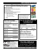
HERE'S HOW TO GET HELP PLEASE HAVE THE MODEL AND SERIAL NUMBER ON-HAND WHEN CALLING MULTIQUIP CORPORATE OFFICE 18910 Wilmington Ave. Carson, CA 90746 Email: mq@multiquip.com Internet: www.multiquip.com PARTS DEPARTMENT 800-427-1244 310-537-3700 MAYCO PARTS 800-306-2926 310-537-3700 SERVICE DEPARTMENT 800-421-1244 310-537-3700 TECHNICAL ASSISTANCE 800-478-1244 WARRANTY DEPARTMENT 800-421-1244, EXT. 279 310-537-3700, EXT.
TABLE OF CONTENTS Multiquip GA-6RE/GA-6REA AC Portable Generators ROBIN EH-360YS2420 ENGINE Here's How To Get Help ............................................ 3 Table Of Contents ..................................................... 4 Parts Ordering Procedures ....................................... 5 Safety Message Alert Symbols .............................. 6-7 Rules for Safe Operation ..................................... 8-10 Operation and Safet Decals ....................................
PARTS ORDERING PROCEDURES When ordering parts, please supply the following information: ❒ ❒ ❒ ❒ ❒ ❒ ❒ Dealer account number Dealer name and address Shipping address (if different than billing address) Return fax number Applicable model number Quantity, part number and description of each part Specify preferred method of shipment: ✓ FedEx or UPS Ground ✓ FedEx or UPS Second Day or Third Day Note: Unless otherwise indicated by customer, all orders are treated as “Standard Orders”, and will ✓ FedEx or UPS Nex
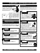
GA-6RE/GA-6REA — SAFETY MESSAGE ALERT SYMBOLS FOR YOUR SAFETY AND THE SAFETY OF OTHERS! HAZARD SYMBOLS Safety precautions should be followed at all times when operating this equipment. Failure to read and understand the Safety Messages and Operating Instructions could result in injury to yourself and others.
GA-6RE/GA-6REA — SAFETY MESSAGE ALERT SYMBOLS CAUTION Rotating Parts Hazards NEVER operate equipment with covers, or guards removed. Keep fingers, hands, hair and clothing away from all moving parts to prevent injury. CAUTION CAUTION Equipment Damage Hazards Other important messages are provided throughout this manual to help prevent damage to your portable generator, other property, or the surrounding environment.
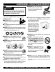
GA-6RE/GA-6REA — RULES FOR SAFE OPERATION DANGER Read this manual! Failure to follow instructions in this manual may lead to serious injury or even death! This equipment is to be operated by trained and qualified personnel only! This equipment is for industrial use only. The following safety guidelines should always be used when operating the GA-6RE/GA-6REA Portable Generators: GENERAL SAFETY ■ DO NOT operate or service this equipment before reading this entire manual.
GA-6RE/GA-6REA — RULES FOR SAFE OPERATION ■ ALWAYS be sure the operator is familiar with proper safety precautions and operation techniques before using generator. ■ NEVER leave the generators unattended, turn off engine when unattended. ■ Unauthorized equipment modifications will void all warranties. ■ ALWAYS ensure generators are on level ground before use. ■ DO NOT place hands or fingers inside generators engine compartment when engine is running.
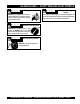
GA-6RE/GA-6REA — RULES FOR SAFE OPERATION DANGER -ELECTROCUTION HAZARDS During operation of this generation, there exists the possibility of electrocution, electrical shock or burn, which can cause severe bodily harm or even DEATH! Emergencies ■ ALWAYS know the location of the nearest fire extinguisher. ■ ALWAYS know the location of the nearest first aid kit. To avoid these hazards: NEVER use damaged or worn cables when connecting equipment to the generator.
GA-6RE/GA-6REA — OPERATION AND SAFETY DECALS Machine Safety Decals The GA-6RE/GA-6REA portable generators are equipped with a number of safety decals (Figure 1). These decals are provided for operator safety and maintenance information. The illustration below shows these decals as they appear on the machine. Should any of these decals become unreadable, replacements can be obtained from your dealer. Figure 1. Operation and Safety Decals GA-6RE/GA-6REA A.C. GENERATORS — OPERATION & PARTS MANUAL — REV.
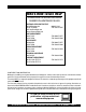
GA-6RE/GA-6REA — SPECIFICATIONS (GENERATOR) Table 1. Specifications (Generators) Model Type Excitation GA-6RE/ GA-6REA Brushless Revolving Field Type Solid State, Statically Excited System AC Generator Speed Cooling System Fuel Capacity 60 Cycle AC Power Source 3,600 RPM Self-Ventilation 5 gallons (19 liters) Continuous Output 5.0 kW Stanby Output 6.0 kW Rated Voltage 120/240V Current Max/Continuous (120V) 50/41.6 amps Current Max/Continuous (240V) 25.0/20.
GA-6RE/GA-6REA — SPECIFICATIONS (ENGINE) Table 2. Specifications (Engine) Engine Model ROBIN EH-360YS2420 Type Air-cooled 4 stroke, Single Cylinder, OHV, Horizontal Shaft Gasoline Engine Bore X Stroke 3.50 in. X 2.56 in. (89 mm x 65 mm.) Displacement 24.67 cu-in (404 cm3) Max Output 11.5 H.P./3600 R.P.M. Fuel Lube Oil Capacity 1.27 quar ts (1.
GA-6RE/GA-6REA — DIMENSIONS Figure 2. Dimensions PAGE 14 — GA-6RE/GA-6REA A.C. GENERATORS — OPERATION & PARTS MANUAL — REV.
GA-6RE/GA-6REA — GENERAL INFORMATION WARNING Before connecting this generators to any building’s electrical system, a licensed electrician must install an isolation (transfer) switch. Serious injury or death may result without this transfer switch.
GA-6RE/GA-6REA — LOAD APPLICATION Single Phase Load — 60 Hz Always be sure to check the nameplate on the generators and equipment to insure the wattage, amperage and frequency requirements are satisfactorily supplied by the generators for operating the equipment. Generally, the wattage listed on the nameplate of the equipment is its rated output.
GA-6RE/GA-6REA — CONTROLS AND INDICATORS Figure 3A. Generator Components 1. 2. 3. 4. Lifting Bail Eye – Attach a rope or chain to this lifting eye when lifting of the generator is required. Never stand underneath the generator while it is being lifted. Place lifting eye in down position when not in use. AC-Voltmeter – This voltmeter indicates (with a mark) the rated 60 Hz (single-phase) output voltage. In addition the voltmeter can also be used as a diagnostic tool.
GA-6RE/GA-6REA — CONTROLS AND INDICATORS Figure 3B. Generator Components 13. Full Power Switch – The generators are provided with a full power switch. Figures 3C and 3D show simplified wiring diagrams of the dual voltage system.
GA-6RE/GA-6REA — CONTROLS AND INDICATORS Figure 3E. Generator Components 14. Fuel Cock Lever – Turn this lever downward to start (down)the flow of fuel into the carburetor. Turn upward to stop (up) the flow of fuel. 20. Engine Oil Drain Plug – Remove this drain plug when draining of the oil from the engine crankcase is required. Fill with recommeded type oil as listed in Table 6. 15. Spark Plug – Provides spark to the ignition system. Set spark plug gap to 0.6 - 0.7 mm (0.028 - 0.
GA-6RE/GA-6REA — GENERATOR REFUELING DANGER Adding fuel to the tank should be done only when the engine is stopped and has had an opportunity to cool down. In the event of a fuel spill, DO NOT attempt to start the engine until the fuel residue has been completely wiped up, and the area surrounding the engine is dry. If generators is placed in a truck bed with a plastic liner, REMOVE generators from truck bed and place on ground (Figure 4) to refuel.
GA-6RE/GA-6REA — INSTALLATION Outdoor Installation Indoor Installation Install the generator/welder in a area that is free of debris, bystanders, and overhead obstructions. Make sure the generators are on secure level ground so that it cannot slide or shift around. Also install the generators in a manner so that the exhaust will not be discharged in the direction of nearby homes. Exhaust gases from gasoline engines are extremely poisonous.
GA-6RE/GA-6REA — INSTALLATION Connecting the Ground The nut and ground terminal on the generators should always be used to connect the generators to a suitable ground. The ground cable should be #8 size wire minimum. At the generator, connect the terminal of the ground cable between the lock washer and the nut (Figure 5) and tighten the nut fully. Connect the other end of the ground cable to a suitable earth ground (ground rod). Figure 5. Generator Grounding PAGE 22 — GA-6RE/GA-6REA A.C.
GA-6RE/GA-6REA — PREINSPECTION Extension Cable General Inspection Prior to Operation Ground Power Tools When using power tools or electrical equipment requireing AC power from the generators, make sure connecting (power tool) cable (Figure 6) has a ground as shown in Figure. When electric power is to be provided to various tools or loads at some distance from the generators, extension cords are normally used.
GA-6RE/GA-6REA — PRE-INSPECTION (ENGINE) CAUTION NEVER operate the generators in a confined area or enclosed area structure that does not provide ample free flow of air. Figure 8. Engine Oil Dipstick (Oil Level) ALWAYS wear approved eye and hearing protection before operating the generator. Before Starting 1. Read safety instructions at the beginning of manual. 2. Clean the generator, removing dirt and dust, particularly the engine cooling air inlet, carburetor and air cleaner. 3.
GA-6RE/GA-6REA — INITIAL START-UP (ENGINE) CAUTION DO NOT attempt to operate this generator until the Safety, General Information and Inspection sections of this manual have been read and thoroughly understood. This section is intended to assist the operator with the initial start-up of the portable generator. It is extremely important that this section be read carefully before attempting to use the generator in the field. Before Starting the Engine 1.
GA-6RE/GA-6REA — INITIAL START-UP/GENERATOR OPERATION 7. If the engine has started, slowly return the choke lever (Figure 12 ) to the “OPEN” position. If the engine has not started repeat steps 1 through 5. 2. Place the full power switch (Figure 19) in the 120V position (up). 8. Before the generators is placed into operation, run the engine for 3-5 minutes. Check for abnormal smells, fuel leaks, and noises that would associate with lose components. 9.
GA-6RE/GA-6REA — GENERATOR OPERATION/SHUTDOWN 5. Read the voltmeter on the front panel of the generators (Figure 22) and verify that 240 VAC is present at the 240V twist-lock receptacle. Using an external voltmeter verify that 120V is present at the 120V twist-lock and GFCI duplex receptacles. Stopping the Engine 1. Place the main circuit breaker (Figure 23) in the OFF position. Figure 23. Main Circuit Breakers (Off) 2. Place the idle control switch (Figure 24) in the OFF position. Figure 24.
GA-6RE/GA-6REA — PREPARATION FOR LONG TERM STORAGE Generator Storage For storage of the generating set for over 30 days, the following is required: ■ Drain the fuel tank completely, or add STA-BIL to the fuel. ■ Run the engine until the gasoline in the carburetor is completely consumed. ■ Completely drain the oil from the crankcase and refill with fresh oil. ■ Remove the spark plug, pour 2 or 3 cc of SAE 30 oil into the cylinder and crank slowly to distribute the oil.
GA-6RE/GA-6REA — MAINTENANCE (ENGINE) Use Table 6 as a general maintenance guideline when servicing your engine. For more detail engine maintenance information, refer to the engine owner's manual supplied with your engine. Table 6. Engine Maintenance Schedule DESCRIPTION (3) OPERATION BEFORE CHECK X FIRST EVERY MONTH 3 MONTHS OR OR 10 HRS. 25 HRS. EVERY 6 MONTHS OR 50 HRS. EVERY YEAR OR 100 HRS. EVERY 2 YEARS OR 200 HRS.
GA-6RE/GA-6REA — MAINTENANCE (ENGINE) Maintenance Perform the scheduled maintenance procedures as defined by Table 6 and below: DAILY ■ Thoroughly remove dirt and oil from the engine and control area. Clean or replace the air cleaner elements as necessary. Check and retighten all fasteners as necessary. Check the gearbox for oil leaks. Repair or replace as needed. WEEKLY ■ Remove the fuel filter cap and clean the inside of the fuel tank. ■ Remove or clean the filter at the bottom of the tank.
GA-6HE — MAINTENANCE (BATTERY) Battery This unit is of negative ground DO NOT connect in reverse. Always maintain battery fluid level between the specified marks. Battery life will be shortened, if the fluid level are not properly maintained. Add only distilled water when replenishment is necessary. DO NOT over fill. Check to see whether the battery cables are loose. Poor contact may result in poor starting or malfunctions. Always keep the terminals firmly tightened.
GA-6RE — WIRING DIAGRAM (GENERATOR) Figure 31. GA-6RE Generator Wiring Diagram PAGE 32 — GA-6RE/GA-6REA A.C. GENERATORS — OPERATION & PARTS MANUAL — REV.
GA-6REA — WIRING DIAGRAM (GENERATOR) Figure 32. GA-6REA Generator Wiring Diagram GA-6RE/GA-6REA A.C. GENERATORS — OPERATION & PARTS MANUAL — REV.
GA-6RE/GA-6REA — TROUBLESHOOTING (ENGINE) Practically all breakdowns can be prevented by proper handling and maintenance inspections, but in the event of a breakdown, please take a remedial action following the diagnosis based on the Engine Troubleshooting (Table 7) and Generator Troubleshooting (Table 8) information shown below and on the proceeding pages. If the problem cannot be remedied, please leave the unit just as it is and consult our company's business office or service plant. TABLE 7.
GA-6RE/GA-6REA — TROUBLESHOOTING (ENGINE) TABLE 7. ENGINE TROUBLESHOOTING (CONTINUED) SYMPTOM Insufficient power output "compression" and overheats Burns to much fuel Exhaust color is continiously "WHITE" Exhaust color is continiously "BLACK" POSSIBLE PROBLEM SOLUTION Malfunction in cooling fan? Check or replace cooling fan. Air in-take filter clogged? Clean or replace air in-take filter. Over accumulation of exhaust products? Clean and check valves. Check muffler, replace if necessary.
GA-6RE/GA-6REA — TROUBLESHOOTING (GENERATOR) TABLE 8. GENERATOR TROUBLESHOOTING SYMPTOM Low voltage POSSIBLE PROBLEM SOLUTION Engine speed too low? Raise engine speed to rated RPM. AC voltmeter not working? Replace Ac voltmeter. Control box internal wiring malfunction? Check control box wiring. Defective ignition coil? Check red and green ignition wires. Replace ignition wires if necessary. Rotor winding malfunction? Check or replace rotor. Stator winding malfunction? Check or replace stator.
NOTE PAGE GA-6RE/GA-6REA A.C. GENERATORS — OPERATION & PARTS MANUAL — REV.
GA-6RE/GA-6REA — EXPLANATION OF CODE IN REMARKS COLUMN How to read the marks and remarks used in this parts book. NOTE The contents of this catalog are subject to change without notice. Items Found In the “Remarks” Column Serial Numbers-Where indicated, this indicates a serial number range (inclusive) where a particular part is used. Model Number-Where indicated, this shows that the corresponding part is utilized only with this specific model number or model number variant.
GA-6RE/GA-6REA — SUGGESTED SPARE PARTS GA-6RE/GA-6REA 1 TO 3 UNITS WITH ROBIN EH-360YS2420 ENGINE 1 to 3 Units Qty. P/N Description 1 ........A9924800014 ...........CAP FUEL TANK 1 ........A9924800004 ...........FILTER FUEL 2 ........3015419604 ..............RUBBER SUSPENSION 2 ........D9312600204 ...........RUBBER SUSPENSION 3 ........0650140150 ..............SPARK PLUG 2 ........2265011308 ..............ROPE, RECOIL 3 ........2673266118 ..............ELEMENT AIR CLEANER 3 ........0642000220 .............
GA-6RE/GA-6REA — NAMEPLATE AND DECALS. NAME PLATE ASSY. PAGE 40 — GA-6RE/GA-6REA A.C. GENERATORS — OPERATION & PARTS MANUAL — REV.
GA-6RE/GA-6REA — NAMEPLATE AND DECALS. NAME PLATE ASSY. NO. PART NO. 1 A5561000003 2 1630680104 3 A5511200402 3 A5511201402 4 5 0800628504 6 A5551000004 7 0820610404 8 35137 9 7900636004 10 8700611804 11 8700611904 12 0800689404 13 0800689504 14 0800696604 PART NAME QTY. REMARKS DECAL; MQ MULTIQUIP 6000 1 DECAL; FUEL COCK .................................................. 1......... S-1407 DECAL; CONTROL PANEL ......................................... 1......... GA-6RE, A51120040 DECAL; CONTROL PANEL .....
GA-6RE/GA-6REA — GENERATOR ASSY. GENERATOR ASSY. PAGE 42 — GA-6RE/GA-6REA A.C. GENERATORS — OPERATION & PARTS MANUAL — REV.
GA-6RE/GA-6REA — GENERATOR ASSY. GENERATOR ASSY. NO. PART NO. 1 7901002503 1-1 * 0601823213 1-2 * 0601822638 1-3 * 0071706304 2 7901017004 3 0801086104 4 0040010000 5 A5135000003 6 7901315502 7 7871315022 8 7875021523 9 7871331003 10 7901316004 11 0040008000 12 0041208000 13 7871329514 14 0601851760 15 0012808020 15A 0040008000 PART NAME QTY. REMARKS ROTOR ASSY. ...................................1 .................. INCLUDES ITEMS W/ * FIELD ASSY. .....................................1 ..................
GA-6RE — CONTROL BOX ASSY. CONTROL BOX ASSY. (GA-6RE) PAGE 44 — GA-6RE/GA-6REA A.C. GENERATORS — OPERATION & PARTS MANUAL — REV.
GA-6RE — CONTROL BOX ASSY. CONTROL BOX ASSY. (GA-6RE) NO. PART NO. PART NAME QTY.
GA-6REA — CONTROL BOX ASSY. CONTROL BOX ASSY. (GA-6REA) PAGE 46 — GA-6RE/GA-6REA A.C. GENERATORS — OPERATION & PARTS MANUAL — REV.
GA-6REA — CONTROL BOX ASSY. CONTROL BOX ASSY. (GA-6REA) NO. PART NO. PART NAME QTY.
GA-6RE/GA-6REA — MUFFLER ASSY. MUFFLER ASSY. PAGE 48 — GA-6RE/GA-6REA A.C. GENERATORS — OPERATION & PARTS MANUAL — REV.
GA-6RE/GA-6REA — MUFFLER ASSY. MUFFLER ASSY.
GA-6RE/GA-6REA — PIPE FRAME ASSY. PIPE FRAME ASSY. PAGE 50 — GA-6RE/GA-6REA A.C. GENERATORS — OPERATION & PARTS MANUAL — REV.
GA-6RE/GA-6REA — PIPE FRAME ASSY. PIPE FRAME ASSY. NO. PART NO.
GA-6RE/GA-6REA — BATTERY ASSY. BATTERY ASSY. PAGE 52 — GA-6RE/GA-6REA A.C. GENERATORS — OPERATION & PARTS MANUAL — REV.
GA-6RE/GA-6REA — BATTERY ASSY. BATTERY ASSY. NO. PART NO. 32 33 7905458103 34 A5344200004 35 0037806000 36 0040006000 37 0041206000 38 A5347000104 39 A5347000004 PART NAME QTY. REMARKS BATTERY ..................................... 1 ................PURCHASE LOCALLY BATTERY BAND 1 BATTER BOLT 2 WING NUT 2 SPRING NUT 2 WASHER, FLAT 2 BATTERY CABLE 1 BATTERY CABLE 1 GA-6RE/GA-6REA A.C. GENERATORS — OPERATION & PARTS MANUAL — REV.
ROBIN EH-360YS2420 ENGINE — AIR CLEANER ASSY. PAGE 54 — GA-6RE/GA-6REA A.C. GENERATORS — OPERATION & PARTS MANUAL — REV.
ROBIN EH-360YS2420 ENGINE — AIR CLEANER ASSY. AIR CLEANER ASSY. NO. PART NO. 510 2673260820 510-220 * 2673272108 510-250 * 2673264008 2673266118 510-520 * 540 2673290103 550 26735901A3 570 0023806000 580 0010406160 850 2671700103 910 0732004430 PART NAME QTY. REMARKS AIR CLEANER ASSY. .............................1 ................ INCLUDES ITEMS W/ * GASKET 1 CLEANER COVER CP 1 AIR CLEANER ASSY. 1 INSULATOR .............................................1 ................ T=15 26.5D 6.
ROBIN EH-360YS2420 ENGINE — CRANKCASE ASSY. CRANKCASE ASSY. PAGE 56 — GA-6RE/GA-6REA A.C. GENERATORS — OPERATION & PARTS MANUAL — REV.
ROBIN EH-360YS2420 ENGINE — CRANKCASE ASSY. CRANKCASE ASSY. NO. PART NO.
ROBIN EH-360YS2420 ENGINE — CRANKSHAFT AND PISTON ASSY. CRANKSHAFT AND PISTON ASSY. PAGE 58 — GA-6RE/GA-6REA A.C. GENERATORS — OPERATION & PARTS MANUAL — REV.
ROBIN EH-360YS2420 ENGINE — CRANKSHAFT AND PISTON ASSY. CRANKSHAFT AND PISTON ASSY. NO. PART NO. PART NAME QTY. REMARKS 10 2672070201 CRANKSHAFT CP 1 40 0230350160 SPACER, 35.3DX45DX0.6T 1 41 0230350170 SPACER, 35.3DX45DX0.8T 1 42 0230350180 SPACER, 35.3DX45DX1.0T 1 50 0021818000 NUT 1 60 0032018000 SPRING WASHER 1 65 0031018000 WASHER 1 70 0053205401 WOODRUFF KEY 1 310 2672250110 CONNECTING ROD ASSY. ................................. 1 .............
ROBIN EH-360YS2420 ENGINE — FLYWHEEL ASSY. FLYWHEEL ASSY. PAGE 60 — GA-6RE/GA-6REA A.C. GENERATORS — OPERATION & PARTS MANUAL — REV.
ROBIN EH-360YS2420 ENGINE — FLYWHEEL ASSY. FLYWHEEL ASSY. NO. PART NO. 10 2677920211 11 2677940121 12 2677960501 13 2677960301 20 2677100203 30 0011406250 35 0043506200 50 2677310101 60 0660000361 70 0150040090 80 2267550103 100 0650140480 110 0655000131 170 2467550201 176 0043106080 PART NAME FLYWHEEL CP IGNITION COIL CP EXCITER COIL CP EXCITER COIL CP RING GEAR, D 180DX217DX7B N=85 BOLT & WASHER AY SCREW & WASHER AY WIRE 1 CP, L=330 BLACK SWITCH AY TAPPING SCREW, M4X12L GROMMET, 8DX12DX7.
ROBIN EH-360YS2420 ENGINE — GOVERNOR ASSY. GOVERNOR ASSY. PAGE 62 — GA-6RE/GA-6REA A.C. GENERATORS — OPERATION & PARTS MANUAL — REV.
ROBIN EH-360YS2420 ENGINE — GOVERNOR ASSY. GOVERNOR OPERATION ASSY. NO. PART NO. PART NAME 10 2674230311 GOVERNOR LEVER CP 20 2674220103 GOVERNOR SHAFT 26 0031108000 WASHER 30 2674270101 GOVERNOR ROD CP 40 2674280113 ROD SPRING, 5.7DX0.4DX148L N=30 50 0031306000 CLIP 60 0011406300 BOLT AND WASHER AY 70 0186060020 NUT, M6X1.0X4.9H SQUARE 80 2674250201 GOVERNOR SPRING CP, 12.5DX1.
ROBIN EH-360YS2420 ENGINE — INTAKE AND EXHAUST ASSY. INTAKE AND EXHAUST ASSY. PAGE 64 — GA-6RE/GA-6REA A.C. GENERATORS — OPERATION & PARTS MANUAL — REV.
ROBIN EH-360YS2420 ENGINE — INTAKE AND EXHAUST ASSY. INTAKE AND EXHAUST ASSY. NO. PART NO. PART NAME 10 2673170101 CAMSHAFT CP 35 2463620111 RELEASE LEVER CP 38 2463670103 RETURN SPRING 50 2393330113 TAPPET 60 2463361103 VALVE SPRING 70 2463371113 SPRING RETAINER 80 2633340103 INTAKE VALVE 90 2633350213 EXHAUST VALVE 95 2463550103 COLLET-VALVE 100 0230220050 SPACER, 22.2DX32.5DX0.6T 101 0230220060 SPACER, 22.2DX32.5DX0.7T 102 0230220070 SPACER, 22.2DX32.5DX0.
ROBIN EH-360YS2420 ENGINE — COOLING STARTING ASSY. COOLING STARTING ASSY. PAGE 66 — GA-6RE/GA-6REA A.C. GENERATORS — OPERATION & PARTS MANUAL — REV.
ROBIN EH-360YS2420 ENGINE — COOLING STARTING ASSY. COOLING STARTING ASSY. NO. PART NO. 10 2675126301 20 2669170303 25 0732003900 40 0110060020 60 2675260112 61 2675270103 80 0110060010 210 2675020110 210-1 2615011508 * 2465012008 210-2 * 2265011308 210-3 * 2615010008 210-4 * 2465012508 210-5 * 2465013008 210-6 * 2275013508 210-7 * 2465016008 210-8 * 2245015008 210-11 * 2275015208 210-49 * 0110060010 220 230 0016508120 850 2675965203 PART NAME QTY.
ROBIN EH-360YS2420 ENGINE — CARBURETOR ASSY. CARBURETOR ASSY. PAGE 68 — GA-6RE/GA-6REA A.C. GENERATORS — OPERATION & PARTS MANUAL — REV.
ROBIN EH-360YS2420 ENGINE — CARBURETOR ASSY. CARBURETOR ASSY. NO. PART NO.
ROBIN EH-360YS2420 ENGINE — STARTER ASSY. STARTER ASSY. PAGE 70 — GA-6RE/GA-6REA A.C. GENERATORS — OPERATION & PARTS MANUAL — REV.
ROBIN EH-360YS2420 ENGINE — STARTER ASSY. STARTER ASSY. NO. PART NO. 120 2247050200 120-2 2357053508 120-3 2357054508 120-4 2357053008 120-6 2357055008 120-7 2247055108 120-8 2247055308 120-9 2467050008 120-10 2357054008 120-11 2467050508 120-12 1137051008 120-17 2357057508 120-23 2357055508 120-29 2147056008 120-40 2357056508 120-41 2357056608 120-52 2467058008 121 0022706000 122 0032006000 130 2147900701 150 0031008000 160 0032008000 170 2467550201 176 0043106080 300 2147700210 PART NAME QTY.
ROBIN EH-360YS2420 ENGINE — SOLENOID ASSY. SOLENOID ASSY. PAGE 72 — GA-6RE/GA-6REA A.C. GENERATORS — OPERATION & PARTS MANUAL — REV.
ROBIN EH-360YS2420 ENGINE — SOLENOID ASSY. SOLENOID ASSY. NO. PART NO. 600 2537501000 610 2677600101 611 2677600211 613 0130060220 614 0011308200 630 2677820113 640 0563000040 642 0566000250 700 KS31102001 760 2147312201 770 0566000250 775 0110060010 PART NAME SOLENOID AY BRACKET (SOLENOID) 1CP BRACKET (SOLENOID) 2CP BOLT & WASHER ASSY., M6X1.0X12LW/W,SW BOLT & WASHER ASSY. SPRING (SOLENOID), 8DX1.2DX103L N=20 WIRE BAND, 3.6BX1.2TX146L CLAMP, 6.5DX10BX95LX0.
TERMS AND CONDITIONS OF SALE — PARTS Effective: October 1, 2002 PAYMENT TERMS 5. Parts must be in new and resalable condition, in the original Multiquip package (if any), and with Multiquip part numbers clearly marked. 6. The following items are not returnable: Terms of payment for parts are net 10 days. FREIGHT POLICY All parts orders will be shipped collect or prepaid with the charges added to the invoice. All shipments are F.O.B. point of origin.
NOTE PAGE GA-6RE/GA-6REA A.C. GENERATORS — OPERATION & PARTS MANUAL — REV.
OPERATION AND PARTS MANUAL HERE'S HOW TO GET HELP PLEASE HAVE THE MODEL AND SERIAL NUMBER ON-HAND WHEN CALLING MULTIQUIP CORPORATE OFFICE 18910 Wilmington Ave. Carson, CA 90746 Email: mq@multiquip.com Internet: www.multiquip.com PARTS DEPARTMENT 800-427-1244 310-537-3700 MAYCO PARTS 800-306-2926 310-537-3700 SERVICE DEPARTMENT 800-421-1244 310-537-3700 TECHNICAL ASSISTANCE 800-478-1244 WARRANTY DEPARTMENT 800-421-1244, EXT. 279 310-537-3700, EXT.