Operation and Parts Manual MODEL ST2010 Series submersible pump Revision #3 (12/07/12) To find the latest revision of this publication, visit our website at: www.multiquip.com THIS MANUAL MUST ACCOMPANY THE EQUIPMENT AT ALL TIMES.
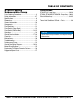
Table of Contents ST2010 Series Submersible Pump Parts Ordering Procedures....................................... 3 Safety Information................................................. 4-7 Specifications........................................................... 8 Dimensions............................................................... 9 General Information................................................ 10 Components........................................................... 11 Float Switches............
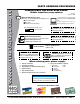
www.multiquip.com Parts Ordering Procedures Ordering parts has never been easier! Choose from three easy options: order via internet (dealers only): best deal! Effective: January 1st, 2006 If you have an MQ Account, to obtain a Username and Password, E-mail us at: parts@multiquip. com. Order parts on-line using Multiquip’s SmartEquip website! ■ View Parts Diagrams ■ Order Parts ■ Print Specification Information To obtain an MQ Account, contact your District Sales Manager for more information.
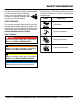
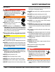
Safety Information Do not operate or service the equipment before reading the entire manual. Safety precautions should be followed at all times when operating this equipment. Failure to read and understand the safety messages and operating instructions could result in injury to yourself and others. Potential hazards associated with the operation of this equipment will be referenced with hazard symbols which may appear throughout this manual in conjunction with safety messages.
Safety Information general SaFeTY CauTion never operate this equipment without proper protective clothing, shatterproof glasses, respiratory protection, hearing protection, steel-toed boots and other protective devices required by the job or city and state regulations. Avoid wearing jewelry or loose fitting clothes that may snag on the controls or moving parts as this can cause serious injury. never operate this equipment when not feeling well due to fatigue, illness or when under medication.
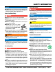
Safety Information pump SaFeTY danger never operate the equipment in an explosive atmosphere or near combustible materials. An explosion or fire could result causing severe bodily harm or even death. Warning Accidental starting can cause severe injury or death. alWaYS place the ON/OFF switch in the OFF position. do noT place hands or fingers inside pump when pump is running. never disconnect any emergency or safety devices. These devices are intended for operator safety.
Safety Information NOTICE alWaYS make certain that the voltage supplied to the pump is correct. Always read the pump’s nameplate to determine what the power requirements are. power Cord/Cable Safety danger never let power cords or cables lay in water. never stand in water while AC power cord is connected to a live power source. never use damaged or worn cables or cords. Inspect for cuts in the insulation. never grab or touch a live power cord or cable with wet hands.
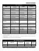
Specifications Type Impeller Table 1. Specifications ST-2010/ST-2010A/ ST-2010B ST-2010CUL Submersible Pump Submersible Pump Cast Ductile Iron Cast Ductile Iron Submersible Trash Pump Cast Ductile Iron Discharge Size 2.00 in. (51 mm) 2.00 in. (51 mm) 2.00 in. (51 mm) Maximum Pumping Capacity Max. Solids Diameter 85 gallons/minute (322 liters/minute) --54.7 ft. (16.6 meters) ST-2010CUL: 50 ft. (15.24 m) 1.0 HP (0.75 kw) 1Ø 115V 63 A ST2010: 13.5 A ST2010A: 13.5 A ST2010CUL: 11.
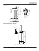
DIMENSIONS ST2010TCUL 49.21 ft. (15 m) 10.23 in. (260 mm.) 23.82 in. (605 mm.) 5.11 in. (130 mm.) 3.14 in. (80 mm.) NPT 2 3.54 in. (90 mm.) 4.52 in. (115 mm.) 4.37 in. (111 mm.) 7.08 in. (180 mm.) ST2010, ST2010A, ST2010B, ST2010CUL 49.21 ft (15m) 16.46 in (418 mm) 6.7 in (170 mm) Dia. Figure 1. ST2010 Series Dimensions ST2010 Series submersible pump • operation and parts manual — rev.
general information Introduction The Multiquip Model ST-2010 submersible pump is designed to pump water and is used for the draining (dewatering) of well casings construction sites, cofferdams, manholes, transformer vaults and excavations. The ST2010TCUL is designed for heavily debris-laden water and the 2-inch discharge port can handle solids up to one inch in diameter.
components ST2010, ST2010A, ST2010B, ST2010CUL ST2010TCUL 6 5 7 3 2 8 4 9 1 Figure 2. Submersible Pump Components Figure 2 shows the location of the basic components for the ST2010 series submersible pumps. Listed below is a brief description of each component. power cable. Always check the cable for signs of wear. NEVER use a defective power cable. Replace the cable immediately if the cable is worn or defective. 1.
float switches Float Switch Theory Design Features Mercury monitoring is a mercury-switch actuated, liquidlevel control that has proven to be more economical and longer lasting than other types of liquid-level control systems, easily replacing and improving upon diaphragm switches, air bubble systems and electro-mechanical switches most often relied upon in the past. Constructed of rigid, durable ABS polymer ultrasonically welded. The all-steel mercury switch is held by positioning pins.
float switch (piggy-back) Float Switch 2. Place the cord into the clamp as shown in Figure 6 Single or dual control float switches (Figure 6) can be used for the unattended operation of the submersible pump. When using the piggy-back power configuration (plug), the ST-2010 series pumps DO NOT require the use of a control box. In this configuration (piggy-back), the SW-1 (single float switch) or SW-2 (dual float switch) are required.
float switch (control box) Control Box For special remote pumping applications of the submersible pump, a control box (Model CB3 - for ST2010, ST2010A, ST2010CUL, and ST2010TCUL and Model CB6 - for ST2010B) may be required. This water-resistant control box provides watertight housing and glands to prevent water from leaking into the box, and a float switch interface. When using the CB3 control box, only the SW-1WOP float switch (2) can be used (no plug, bare wires). Figure 7.
float switch (control box) Figure 8. CB6 Control Box and Dual Float Switch Application Diagram ST2010 Series submersible pump • operation and parts manual — rev.
operation Hose Connections Connect a 2-inch hose to the discharge port on the pump as shown in Figure 9. Make sure that the hose is attached correctly to the discharge port. Pump Power Connections (Piggy-Back Cord Only) 1. Make sure the circuit breaker supplying power to the pump is in the OFF position. 2. Connect the float switch or switches to the AC power receptacle as shown in Figure 6. Attaching Lifting Rope 1.
control box installation DANGER The ST2010 Series submersible pumps are designed to work with a control box. The control box contains the necessary electronics (float switch connections) to operate the pump. Remember the control box contains hazardous voltages. Disconnect all sources of power before installing or servicing.
control box installation Connecting AC Power to the Control Box 1. The AC power cord (input) should have three wires. Each wire is color coded. The colors are WHITE, BLACK and GREEN. 2. Remove the AC input connector housing from the control box, then route the power cord through the cable gland on the control box. 3. Connect the AC power cord to the contactor as shown in Figure 7 and Table 6. Table 6.
clean-up Pump Shut-Down/Clean-up 1. Remove the power from the pump by turning off the circuit breaker or switch that provides power to the pump. Remember to make sure that hands are dry (not wet), and feet are not standing in water when removing disconnecting power from the pump. 2. Using the lifting rope, lift the pump up from its current position. Remove the discharge hose from the discharge port on the pump. 3. Remove all power cables and float switches from the control box.
maintenance LUBRICATION To check the oil level of the mechanical seal perform the following: 1. Lay the pump (Figure 12) on its side with the oil plug facing upwards. 2. Remove oil fill plug. 3. Visually inspect oil plug hole to verify that oil cavity is full enough to cover seal spring. Check every 300 hours. Change hydraulic oil every 6 months (1,000 hours) or as needed. 5. If oil level is low, fill with SAE 10 weight non-detergent hydraulic oil (i.e. Shell Turbo 32 or equivalent).
troubleshooting Symptom Pump Fails To Start Pump Fails to Deliver Full Output Water in Seal Oil Troubleshooting (pump) possible problem Solution Check that proper voltage is being supplied to the pump. Also check that there is an adequate Incorrect voltage/amps? amount of current (amps) to run the pump. Check power source circuit breaker. If using float switches check wiring, inspect Check electrical connections? power cord. Blown power fuse? Replace fuse, check cause of blown fuse.
performance curves ST2010TCUL METERS FT. 60 50 15 40 10 TOTAL HEAD 30 20 5 10 0 GALLONS PER MINUTE 0 40 20 LITERS PER MINUTE 100 300 200 100 80 60 PUMPING CAPACITY ST2010CUL 60 METERS FT. 50 15 40 10 TOTAL HEAD 30 20 5 10 0 GALLONS PER MINUTE 0 40 20 LITERS PER MINUTE 200 100 80 60 100 300 PUMPING CAPACITY ST2010, ST2010A, ST2010B METERS FT.
control box wiring diagram CB3 CONTROL BOX WIRING DIAGRAM CONTACTOR WHITE PUMP POWER CORD SUBMERSIBLE PUMP T1 BLACK WHITE GREEN INPUT POWER CORD L1 BLACK EXTERNAL 1-PHASE (115 VAC, 60 Hz.) POWER SOURCE CIRCUIT BREAKER BLACK L1 L2 GND COIL WHITE GREEN GREEN POWER ON LAMP T2 CHASSIS GND. GROUND WHITE L2 BLACK OPERATION SWITCH CHASSIS GND.
control box wiring diagram page 24 —ST2010 Series submersible pump • operation and parts manual — rev.
motor wiring diagram ST-2010, ST-2010A, ST-2010B, ST-2010CUL ELECTRIC MOTOR WIRING DIAGRAM LEAD WIRES AC POWER CORD U V MAIN COIL BLACK (LINE) AUX. COIL WHITE (NEUTRAL) GREEN (GROUND) CAPACITOR CENTRIFUGAL SWITCH ST2010-TCUL ELECTRIC MOTOR WIRING DIAGRAM LEAD WIRES AC POWER CORD U V MAIN COIL BLACK (LINE) AUX. COIL WHITE (NEUTRAL) GREEN (GROUND) CAPACITOR CAPACITOR CENTRIFUGAL SWITCH ST2010 Series submersible pump • operation and parts manual — rev.
explanation of code in remarks column The following section explains the different symbols and remarks used in the Parts section of this manual. Use the help numbers found on the back page of the manual if there are any questions. NOTICE The contents and part numbers listed in the parts section are subject to change without notice. Multiquip does not guarantee the availability of the parts listed. Sample parTS liST no. 1 2% 2% 3 4 parT no. parT name qTY. remarkS 12345 BOLT .....................1 .....
suggested spare parts ST-2010 SERIES SUBMERSIBLE PUMP 1 TO 3 UNITS Qty. P/N Description 1 ...........0202010T120........ACCORD WITH GLAND 1............0202010T081 .......OIL SEAL 1............0202010T112........OIL SEAL 1............0202010T008........PACKING, CASING 1............0202010T060........MECHANICAL SEAL 1............0202010T074........PACKING 1............0202010T157........PACKING 1............0202010T003........
ST2010TCUL pump assy. 128 127 128 236 120 121 158 123 224 125 156 122 157 828 34 820 445 238 42 7 446 76 81 448 119 23 160 447 65 3 24 5 16 6 8 74 4 112 60 1 530 531 page 28 —ST2010 Series submersible pump • operation and parts manual — rev.
ST2010TCUL pump assy. NO. 1 3 4 5 6 7 8 16 23 24 34 42 60 65 74 76 81 112 119 120 121 122 123 125 127 128 156 157 158 160 224 236 445 446 447 448 820 238 828 530 531 PART NO.
ST2010, ST2010A, ST2010B, ST2010CUL pump assy. 265 641 125 120 236 263 266 121 563 103 123 122 174 60 65 131 214-1 1 224 132 474 299 129 179 445 119 446 81 130 447 160 47 3 6 5 214-2 4 8 176 177 112 146 147 page 30 —ST2010 Series submersible pump • operation and parts manual — rev.
ST2010, ST2010A, ST2010B, ST2010CUL pump assy. NO. 1 3 3 3 4 5 6 8 47 47 60 65 81 102 103 112 119 119 119 119 120 120 120 120 121 122 123 125 127 127 127 129 129 130 131 131 132 146 147 160 174 174 174 PART NO.
ST2010, ST2010A, ST2010B, ST2010CUL pump assy. 265 641 125 120 236 263 266 121 563 103 123 122 174 60 65 131 214-1 1 224 132 474 299 129 179 445 119 446 81 130 447 160 47 3 6 5 214-2 4 8 176 177 112 146 147 page 32 —ST2010 Series submersible pump • operation and parts manual — rev.
ST2010, ST2010A, ST2010B, ST2010CUL pump assy. NO. 176 176 176 177 178 179 214-1 214-2 224 236 263 265 266 299 299 299 431 445 445 445 446 446 446 446 447 447 447 474 475 563 641 PART NO.
electric motor assy. page 34 —ST2010 Series submersible pump • operation and parts manual — rev.
electric motor assy. NO. 112* 268* 269* 270* 273* 445-1* 445-2* 446* 447-1* 447-2* 539* 540* 606* 607* 608 * 822* A PART NO. 0202010T112 0202010T268 0202010T269 0202010T270 0202010T273 0202010T4451 0202010T4452 0202010T446 0202010T4471 0202010T4472 0202010T539 0202010T540 0202010T606 0202010S607 0202010T608 0202010T822 0202010T119 PART NAME QTY.
Terms and Conditions of Sale — Parts paYmenT TermS 5. Parts must be in new and resalable condition, in the original Multiquip package (if any), and with Multiquip part numbers clearly marked. 6. The following items are not returnable: Multiquip reserves the right to quote and sell direct to Government agencies, and to Original Equipment Manufacturer accounts who use our products as integral parts of their own products. a. SpeCial expediTing ServiCe Terms of payment for parts are net 30 days.
notes ST2010 Series submersible pump • operation and parts manual — rev.
Operation and Parts Manual HERE’S HOW TO GET HELP PLEASE HAVE THE MODEL AND SERIAL NUMBER ON-HAND WHEN CALLING United StateS Multiquip Corporate Office 18910 Wilmington Ave. Carson, CA 90746 Contact: mq@multiquip.com MQ Parts Department Tel.