OPERATION MANUAL MODEL ST4125G/ST6125G SUBMERSIBLE PUMP Revision #0 (11/18/10) To find the latest revision of this publication, visit our website at: www.multiquip.com THIS MANUAL MUST ACCOMPANY THE EQUIPMENT AT ALL TIMES.
TABLE OF CONTENTS ST4125G/ST6125G Submersible Pump Table Of Contents .................................................... 2 Parts Ordering Procedures ...................................... 3 Safety Information ................................................ 4-7 Specifications............................................................ 8 Dimensions .............................................................. 9 General Information .............................................. 10 Components ..............
NOTES ST4125G/ST6125G SUBMERSIBLE PUMP• OPERATION MANUAL — REV.
SAFETY INFORMATION Do not operate or service the equipment before reading the entire manual. Safety precautions should be followed at all times when operating this equipment. Failure to read and understand the safety messages and operating instructions could result in injury to yourself and others. Potential hazards associated with the operation of this equipment will be referenced with hazard symbols which may appear throughout this manual in conjunction with safety messages.
SAFETY INFORMATION GENERAL SAFETY CAUTION NEVER operate this equipment without proper protective clothing, shatterproof glasses, respiratory protection, hearing protection, steel-toed boots and other protective devices required by the job or city and state regulations. Avoid wearing jewelry or loose fitting clothes that may snag on the controls or moving parts as this can cause serious injury. NEVER operate this equipment when not feeling well due to fatigue, illness or when under medication.
SAFETY INFORMATION PUMP SAFETY DANGER NEVER operate the equipment in an explosive atmosphere or near combustible materials. An explosion or fire could result causing severe bodily harm or even death. WARNING Accidental starting can cause severe injury or death. ALWAYS place the ON/OFF switch in the OFF position. DO NOT place hands or fingers inside pump when pump is running. NEVER disconnect any emergency or safety devices. These devices are intended for operator safety.
SAFETY INFORMATION NOTICE ALWAYS make certain that the voltage supplied to the pump is correct. Always read the pump’s nameplate to determine what the power requirements are. Power Cord/Cable Safety DANGER Control Box Safety DANGER ALWAYS have a qualified electrician perform the control box installation. The possibility exists of electrical shock or electrocution. NOTICE NEVER let power cords or cables lay in water.
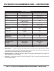
ST4125G/ST6125G SUBMERSIBLE PUMP — SPECIFICATIONS Model Type Impeller Discharge Size Max Solids Maximum Pumping Capacity Max Head Power Voltage/Phase Starting Amps Running Amps Max Starts/Hr. Enclosure Type Insulation Class Max Temperature Control Box Required Power Cable Length Dry Weight Max Height Max Diameter Table 1. Specifications ST4125G Centrifugal Submersible Pump Cast Ductile Iron 4.00 in. (101 mm) .078 in (2 mm) 380 gallons/minute (1,438 liters/minute) 111 ft. (33.8 meters) 10 HP (7.
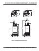
ST4125G/ST6125G SUBMERSIBLE PUMP — DIMENSIONS 12.72 in. (323 mm) 12.72 in. (323 mm) 6.97 in. (177 mm) 6.97 in. (177 mm) 16.89 in. (429 mm) 15.47 in. (393 mm) 5.90 in. (150 mm) 3.94 in. (100 mm) 35.67 in. (906 mm) ST4125G 34.21 in. (869 mm) ST6125G 30.67 in. (779 mm) 28.9 in. (734 mm) 4.57 in. (116 mm) 4.57 in. (116 mm) 11.89 in. (302 mm) 11.89 in. (302 mm) Figure 1. ST4125G/ST6125G Pump Dimensions ST4125G/ST6125G SUBMERSIBLE PUMP• OPERATION MANUAL — REV.
ST4125G/ST6125G — GENERAL INFORMATION The Multiquip Model ST4125G and ST6125G submersible pumps are designed to pump water. These pumps work best when faced with high head applications where you need an appreciable flow. Each pump has dual voltage capability, easily switched between 230 and 460 volts. These pumps have a heavy-duty cast iron body that is very durable and able to withstand rough handling.
ST4125G/ST6125G — COMPONENTS 4 4 5 5 6 3 6 3 2 2 8 1 8 1 7 7 Figure 2. Submersible Pump Components Figure 2 shows the location of the basic components, for the ST4125G and ST6125G submersible pumps. Listed below is a brief explanation of each component. 1. Strainer Base – This strainer base is made of stainless steel which is resistant to hardware corrosion. For dewatering purposes, always place the strainer base on a platform. 2.
FLOAT SWITCHES Mechanical Float Switch Design Features Mechanically activated float switches offer a reliable low current control for dewatering applications. Float switch housings are constructed of high-impact, corrosion resistant polypropylene with mechanically activated, snap action contacts. How It Works The mechanical float switch control will turn ON (close) when the float tips 45° above -horizontal, indicating a high level, and turns OFF (opens) when the float switch drops 45° below horizontal.
FLOAT SWITCHES Float Switches Mounting The Float Switches For unattended operation of the submersible pump two single float switches (Model SW-1WOPA) will be required. These float switches can be connected directly to a control box (bare wires) and will allow the pump to turn on and off depending on the length of the tether. 1. Determine the required cord tether length as shown in Figure 3 and Table 2. 2. Place the cord into the clamp as shown in Figure 6. 3.
FLOAT SWITCHES CB12/CB14 Control Boxes For remote pumping applications, both submersible pumps, require a control box (Figure 7). CAUTION! HIGH VOLTAGE! The CB12 control box requires 230VAC, 3-phase input voltage for normal operation, while the CB14 control box requires 460VAC, 3-phase input voltage. Reference Table 3 for the desired heater. The heater size is determined by the the full load amps the pump will draw.
CONTROL BOX INSTALLATION Control Box Installation CONTROL BOX MOUNTING The following procedure outlines the steps for connecting the pump to a control box. Mount the control box in an upright vertical position. Make sure the control box is securely fastened to a flat surface, that is free of dust, dirt, moisture or any elements that may contaminate or erode the electronic components of the control box. DANGER The ST4125G and ST6125G submersible pumps are designed to work with a control box.
CONTROL BOX INSTALLATION Connecting SW-1WOPA Float Switches to Control Box 1. Remove the float switch input connector housing, then route the float switch wires through the cable gland on the control box. Attach the wires of the float switch to the terminal block as indicated by Table 5 and Figure 9. Table 5. Dual Float switch Connections Float Terminal Wire Switch Block No. Color TB1-A1 Black Start TB1-A2 White TB1-A3 Black Stop TB1-A4 White 2.
230/460 VAC VOLTAGE SELECTION 230/460 VAC Voltage Selection The ST4125G/ST6125G submersible pumps are factory set at 230 VAC.
CB12/CB14 CONTROL BOX POWER CONNECTIONS 3-Phase Power Installation (Input to Control Box) 3-Phase Power Installation (Output To Pump) 1. The 3-phase input power cord should have four wires. Each wire is color coded. The colors are RED, WHITE, BLACK and GREEN. 1. The 3-phase output power cord should have four wires. Each wire is color coded. The colors are RED, WHITE, BLACK and GREEN. 2.
CB12/CB14 CONTROL BOX WIRING LAYOUT MOUNT CONTROL BOX IN AN UP-LEFT VERTICAL POSITION AS SHOWN. 4- H1 75VA TEMP. CL. U.S. PAT. NO. 3516040 C FN M-8/10 XF 50/60HZ 105 ImperviTRAN (R ) -3 B075BTZ13JK CONTROLLER CAT. NO.
OPERATION Pump Placement LOWER LOWER 1. Attach a suitable lifting chain to the eye bolts (Figure 10) on the pump. Use a crane, or similar lifting device and lower the pump into place. For applications where there is an excessive amount of mud, grit or silt, the use of a support platform is desirable. 2. Make sure the pump is always placed in an upright position, not tilted (Figure 11). Never position the pump directly on a soft, loose bottom.
OPERATION 1. From the voltage source, set the circuit breaker or quick disconnect switch to the ON position. 2. For manual operation of the pump, place the 3-position operation switch (Figure 12) on the control box in the MANUAL position. 1. When the electronic overload module detects an overload condition, the pump will shut down. Check the pump and correct the cause of ther overload. 2. Let the pump cool down, then press the RESET button (see Figure 15) on the front of the control box to restore power.
MAINTENANCE Lubrication Inspecting Lubrication Oil (Mechanical Seal) To check the lubrication oil level of the mechanical seal perform the following: 1. Block the oil fill opening with a finger and roll pump to one side to drain (Figure 18) oil into a small transparent container. Checking Lubrication Oil Level 1. Lay the pump (Figure 17) on its side with the oil plug facing upwards. 2. If oil is cloudy (milky) or has water in it, indicates that mechanical seal is defective or worn.
MAINTENANCE Impeller Removal NOTICE Refer to the the following procedure and Figure 19 for the removal of the impeller. Clearance between impeller and wear plate should be between .011~.019 in. (0.3~0.5 mm). If impeller is defective or badly worn, replace immediately. 1. Remove oil plug (item 193) and o-ring (item 194). Drain oil from oil chamber as referenced in Figure 18. 2. Remove suction strainer/ring stand (item 84A). 3.
MAINTENANCE Electrical Insulation Testing NOTICE Why perform electrical insulation testing? Insulation resistance is moisture and temperature sensitive. When temperature increases, insulation resistance decreases, and vice versa. Electrical insulation starts to age as soon as it is made. Harsh environments, especially those with extreme temperature changes and/or chemical contamination, cause further deterioration of the insulation (power cord).
TROUBLESHOOTING Table 8. Pump Troubleshooting SYMPTOM Pump Fails To Start POSSIBLE PROBLEM Incorrect voltage/amps? Check that the proper voltage, 230 or 460 VAC, 60 Hz, 3-phase is being supplied to the pump. Also check that there is an adequate amount of current (amps) to run the pump. Check power source circuit breaker. Check electrical connections? If using float switches check wiring, inspect power cord.
CB12/CB14 CONTROL BOX WIRING DIAGRAM EXTERNAL 3-PHASE (230 OR 460 VOLT) POWER SOURCE CB-12/CB-14 POWER INPUT CIRCUIT BREAKER L1 L2 L2 L3 L3 GREEN L3 M RED AWG 8 L1 L1 RED WHITE BLACK L2 THREE PHASE WIRING CONNECTIONS H1 RED RED AWG 8 WHT RED AWG 8 BLK H3 H2 T1 GRN PUMP T2 MOTOR T3 H4 SEE TABLE 2 FOR CORRECT HEATER SELECTION CONTROL TRANSFORMER 50VA CPT GROUND F1 XF FUSE 1/2 AMP O/L WHT X2 X1 GRN 2 MAN 4 AUTO BLK 1 OVERLOAD RELAY OFF O/L ON INDICATOR LAMP RED AWG 10 RE
NOTES ST4125G/ST6125G SUBMERSIBLE PUMP• OPERATION MANUAL — REV.
OPERATION AND PARTS MANUAL HERE’S HOW TO GET HELP PLEASE HAVE THE MODEL AND SERIAL NUMBER ON-HAND WHEN CALLING UNITED STATES Multiquip Corporate Office 18910 Wilmington Ave. Carson, CA 90746 Contact: mq@multiquip.com MQ Parts Department Tel.