
Septic System User Manual

COMPONENTS
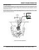
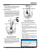
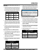
Figure 3. Submersible Pump Components
Figure 3 shows the location of the basic components, for
the CX400/PX400 submersible pumps. Listed below is a
brief explanation of each component
1. AC Power Cable – This unit is supplied with a 19 ft.
(approximately 6 m) AC power cable with a grounding-
type plug. Always check the cable for signs of wear.
use a defective power cable.
2. – Always carry the submersible pump
by its handle. carry the pump by its power
cord. Carrying or lifting the pump by the power cord
will cause undue stress on the cord and can ultimately
dislodge the cord from the pump.
3. – This pump is
equipped with a thermal overload protection device
that will shut down the motor in the event of high
operating temperatures. The motor will automatically
restart once the temperature returns to an acceptable
operating temperature.
4. Mechanical Seal – The hydraulic oil in the pump cavity
is designed to provide cooling for the pump seal. This
SUBMERSIBLE
PUMP
1
2
6
3
8
7
4
5
allows the pump to run dry for a limited period of time
5. – Connect a 2-inch hose to this port.
Remember to adequately support the discharge hose
to avoid stress on the pump.
6. – Remove this plug to check
and add lubrication oil (Paraffin P70 lubricant) to the oil
cavity. This oil protects the mechanical seal. Oil cavity
should be full enough to cover seal spring.
7. – Impellers are constructed of
abrasion-resistant plastic to minimizes wear and
prolong service life.
8. Electric Motor – These submersible pumps utilize a
60 Hz, single-phase, 115 VAC, 1/2 HP electric motor.
Consult with a licensed electrician before connecting
motor to a power source and control boxes. Observe
all city and local safety codes.