Operation and parts Manual MODEL TP24 Tile Saw (Electric Motor) Revision #2 (04/12/12) To find the latest revision of this publication, visit our website at: www.multiquip.com THIS MANUAL MUST ACCOMPANY THE EQUIPMENT AT ALL TIMES.
Proposition 65 Warning Engine exhaust and some of its constituents, and some dust created by power sanding, sawing, grinding, drillingandotherconstructionactivities contains chemicals known to the State of California to cause cancer, birth defects and other reproductive harm. Some examples of these chemicals are: Leadfromlead-basedpaints. Crystalline silicafrombricks. Cementandothermasonryproducts. Arsenicandchromiumfromchemically treatedlumber.
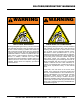
Silicosis/Respiratory Warnings WARNING WARNING SILICOSIS WARNING RESPIRATORY HAZARDS Grinding/cutting/drilling of masonry, concrete, metal and other materials with silica in their composition may give off dust or mists containing crystalline silica. Silica is a basic component of sand, quartz, brick clay, granite and numerous other minerals and rocks. Repeated and/or substantial inhalation of airborne crystalline silica can cause serious or fatal respiratory diseases, including silicosis.
Table of Contents TP24 Tile Saw Proposition 65 Warning............................................ 2 Silicosis/Respiratory Warnings................................. 3 Table Of Contents..................................................... 4 Parts Ordering Procedures....................................... 5 Safety Information................................................. 6-9 Specifications......................................................... 10 Dimensions..............................................
www.multiquip.com parts ordering procedures Ordering parts has never been easier! choose from three easy options: order via Internet (dealers only): Best deal! Effective: January 1st, 2006 If you have an Mq Account, to obtain a Username and Password, E-mail us at: parts@multiquip. com. Order parts on-line using Multiquip’s SmartEquip website! ■ View Parts Diagrams ■ Order Parts ■ Print Specification Information To obtain an Mq Account, contact your District Sales Manager for more information.
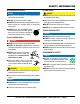
Safety Information Do not operate or service the equipment before reading the entire manual. Safety precautions should be followed at all times when operating this equipment. Failure to read and understand the safety messages and operating instructions could result in injury to yourself and others. Potential hazards associated with the operation of this equipment will be referenced with hazard symbols which may appear throughout this manual in conjunction with safety messages.
Safety Information generaL SaFeTy CauTIon never operate this equipment without proper protective clothing, shatterproof glasses, respiratory protection, hearing protection, steel-toed boots and other protective devices required by the job or city and state regulations. Avoid wearing jewelry or loose fitting clothes that may snag on the controls or moving parts as this can cause serious injury. never operate this equipment when not feeling well due to fatigue, illness or when under medication.
Safety Information SaW SaFeTy danger never operate the equipment in an explosive atmosphere or near combustible materials. An explosion or fire could result causing severe bodily harm or even death. WarnIng Accidental starting can cause severe injury or death. aLWayS place the ON/OFF switch in the OFF position. Keep hands away from moving parts at all times. never disconnect any emergency or safety devices. These devices are intended for operator safety.
Safety Information eLeCTrIC moTor SaFeTy NOTICE LIFTIng SaFeTy CauTIon Operate electric motor only at the specified voltage indicated on the nameplate. never allow any person or animal to stand underneath the equipment while lifting. do noT spray water onto electric motor. Some saws are very heavy and awkward to move around. Use proper heavy lifting procedures. aLWayS disconnect AC power plug from power source before moving saw, changing blade, or performing maintenance.
SPECIFICATIONS Table 1. Saw Specifications Model Blade Capacity Blade RPM Arbor Size Blade Guard Blade Shaft Bearings Cutting Head Conveyor Cart Drive System Max. Depth of Cut Straight Cut Diagonal Cut Water Tray Water Pump Weight TP24 10 in. (254 mm) 3200 5/8 in. (15.875 mm) Cast Aluminum Water-Cooled Cast Aluminum, Adjustable Aluminum with roller bearings, injected molded rubber pad, transportation lock V-belt 3-1/2 in. (90 mm) 24 in. (610 mm) 16 in. (406 mm) x 16 in.
dimensions C B A Figure 1. Dimensions Table 3. Dimension Reference Letter Dimensions A 36.5 in. (927 mm) B 26 in. (660 mm) C 20.4 in. (518 mm) TP24 TILE SAW • operation and parts manual — rev.
general information The TP24 is a powerful, robust saw designed to professionally handle large-sized cuts on ceramics, stone, and masonry materials. A sturdy steel precision frame and easily removable ABS water tray provides overall durability and longevity. Accessories/Replacement Parts This saw is equipped with a trusted high-torque 2 HP electric motor that operates on standard 115 V power and is designed with thermal overload and fan air cover protection.
notes TP24 TILE SAW • operation and parts manual — rev.
saw components 5 9 3 1 8 4 11 2 10 12 22 7 13 6 14 17 23 19 21 20 16 18 15 24 Figure 2. Saw Components page 14 — TP24 TILE SAW • operation and parts manual — rev.
saw components Figure 2 shows the location of the basic components of the TP24 saw. Listed below is a brief explanation of each component. 1. AC Power Cord — Plug this cord into a 125 VAC receptacle when starting of the electric motor is required. 2. V-belt Cover — Remove this cover to access the drive V-belt. NEVER operate the saw with the V-belt cover removed 3. Rubber Splash Guard — Keeps water from splashing from the blade. 4. Electric Motor — This unit uses a 115V, 60 Hz, 2 HP electric motor. 5.
electric motor components/set-up Electric Motor Components Figure 3 shows the location of the components of the electric motor. 115 VAC, 60 Hz SINGLE -PHASE ELECTRIC MOTOR OVERCURRENT BREAKER BUTTON 3. Slide water pump onto U-shaped bracket located at the bottom of the frame. See Figure 6. 4. Slide cutting head onto the post. Secure cutting head to the shaft using provided flat washer, lock washer and nut.
set-up 8. Insert the water pump power plug into the outlet cable receptacle from the electric motor conduit box as shown in Figure 7. ELECTRIC MOTOR CONDUIT BOX CONDUIT BOX CABLE RECEPTACLE POWER PLUG WATER PUMP Figure 5. Support Stand Assembly WARNING connecting the water Pump Disconnect the pump before attempting to handle the pump. NEVER operate pump without water in the tray. Refer to Figure 6. 4. Attach the water hose coming from the blade guard and bearing housing to the water pump. 5.
set-up Blades WARNING Failure to thoroughly inspect the blade for operational safety could result in damage to the blades or the saw and may cause serious injury to the user or others in the operating area. Inspect the blade flanges and shaft for damage before installing the blade. Blade Components Diamond blades are recommended for your saw. Ask your Multiquip dealer about your specific cutting application. Figure 8 highlights the components of a diamond blade. 2 1 3 4 SPECIFICATIONS MAX.
set-up Blade Installation Refer to Figure 9 and the following instructions for installing the blade. 1. Loosen blade guard adjustment knob located at the rear of the blade guard. Carefully raise the cutting head to its highest position and secure it into place by tightening the blade guard adjustment knob. 2. Remove the blade shaft nut and outer flange. If a blade has been mounted, hold the blade with one hand and use the other hand to loosen the nut with the universal wrench. Remove existing blade. 3.
set-up/sawing guides Connecting the Power 1. Place the power ON/OFF switch (Figure 10) in the OFF position (down). 2. Connect an extension cord of adequate current carrying capacity to the power plug on the electric motor. 3. MAKE CERTAIN that the correct size extension cord is used. Undersized wires will burn out motors. Use Table 6 to determine the correct extension cord size. Motor 2 HP Table 6. Extension Cord Sizes 75 ft 50 ft 25 ft Voltage (7.6 m) (15. 2 m) (22.9 m) VAC Long Long Long 115 No. 12 No.
sawing guides Using the Rip Guide 1. Set the rip guide at the desired location on the ruler guide and tighten the threaded knob. Make sure that the rip guide is firmly tightened to avoid slippage. The rip guide can be used for 45° and 90° cuts. 2. After the rip guide is positioned, for the desired cut, place material flat against the rip guide and ruler guide. 3. Now you are ready to make your cut. Performing Diagonal Cuts 1.
operation Start-up Procedure NOTICE Read and fully understand this manual before starting or attempting to operate the saw. Before starting the saw’s electric motor make sure that the Safety, General Information, and Set-Up sections have been completed and understood. DO NOT proceed until the above mentioned sections have been completed. WARNING NEVER lift the blade guard while the blade is rotating.
operation 3. Push the cutting table with the material, slowly and evenly until the cut is complete. Move the cutting table back and remove the cut pieces. 4. Avoid overloading the motor when cutting. However, the electric motor is protected with a manual-reset thermal overload switch that will turn the saw off if the motor is overheated. In the event that the switch is tripped, turn the “ON/OFF” switch to the “OFF” position and allow the motor to cool before attempting to restart. Shut down Procedure 1.
MAINTENANCE A good preventive maintenance program of regular inspection and care will increase life and improve the performance of the saw and cutting blades. WARNING Whenever cleaning, adjusting, or lubricating any part of the saw, MAKE CERTAIN to do the following: • Place power ON/OFF switch to the OFF position. • Disconnect power cord from AC source. • NEVER attempt to check the V-belt with the engine running. Severe bodily injury can occur. Basic Maintenance 1.
MAINTENANCE Maintenance intervals Use the following guidelines to perform maintenance on your saw. After every use of the machine Remove dirty water from container. Remove dirt and mud from the bottom of the container. Rinse the immersion pump with fresh water to prevent water pump clogging from residual dirt. After wet cleaning and before using the machine again Connect the machine to an electric power outlet equipped with a “GFCI” safety power breaker.
MAINTENANCE Water pump maintenance When the machine has not been used for a long period of time, hard packed dirt may build up inside the pump and block the pump wheel. NOTICE If the machine is activated with the immersion pump blocked, the electric motor will be damaged within a few minutes! Please follow the steps below to clean the pump before operating the saw. 1. Remove the immersion pump from the water container. 2. Clean the immersion pump. Figure 18. Belt Replacement 3.
MAINTENANCE BELT GUARD BELT ADJUSTMENT SCREW PULLEY BEARING HOUSING INNER FLANGE Figure 19. Bearing Housing Removal Bearing Housing Installation To install a new bearing housing, perform the following: 1. Make sure that the old housing has been properly removed. 2. Unpack the new bearing housing and place the flat portion face-down on a towel situated on a flat surface. 3. Secure the cutting head in a in a completely horizontal position. 4.
MAINTENANCE realignment required. However, if scenario A or B (described below) occurs, other adjustments may be required instead. Method 1 This procedure deals with the most common source of misalignment that occurs when the guide rails are not parallel with the blade. 1. Set the cutting depth such that the blade passes through the table, not over. a.
MAINTENANCE Method 2 This procedure corrects another source of misalignment that occurs when the table’s orientation is not parallel with the guide rails. 1. Use the universal wrench to loosen (but not remove) the fasteners from either end of both guide rails. Move each rail away from the other, so that the horizontal rollers are clear of the right guide rail. See Figure 23. HORIZONTAL ROLLER CLEARANCE RIGHT GUIDE RAIL 1 GUIDE ROLLER 2 HORIZONTAL ROLLER LEFT GUIDE RAIL Figure 25.
MAINTENANCE Leveling Adjustment Transporting the saw This procedure levels the table so that it is perpendicular to the blade and flush against the rails. 1. Ensure that the water tray is empty and dry. 1. Remove rubber caps B and C on the right side of the table. Loosen the exposed lock nuts using a socket wrench. Next, use a flat screwdriver to turn the shaft of the rollers clockwise. See Figure 24. This will lower the horizontal rollers to allow room for adjusting the flat rollers. 2.
wiring diagram (electric motor) Black White Green Power Outlet for Water Pump Black Motor White Green Power Cable n ee Gr White White Switch Black Black Black Overcurrent Breaker Wiring Box Figure 28. Electric Motor Wiring Diagram TP24 TILE SAW • operation and parts manual — rev.
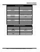
troubleshooting (blade) Table 7. Blade Troubleshooting Symptom Irregular run of the saw blade Possible Problem Poor tension in the blade material Solution Return saw blade to manufacturer Have the saw blade aligned/flattened Saw blade is damaged or bent Saw blade wobbles when running Diamond segment becomes loose Excessive wear Cracks in or near diamond segment Chean the receiving flange Replace saw blade.
troubleshooting (Saw) Table 8.
Explanation of Code in Remarks Column The following section explains the different symbols and remarks used in the Parts section of this manual. Use the help numbers found on the back page of the manual if there are any questions. NOTICE The contents and part numbers listed in the parts section are subject to change without notice. Multiquip does not guarantee the availability of the parts listed. SampLe parTS LIST no. 1 2% 2% 3 4 parT no. parT name QTy. remarKS 12345 BOLT .....................1 .....
Suggested Spare Parts TP24 tile saw with electric motor 1 to 3 units Qty. P/N Description 1............tp100072..............v-belt 1............tpS100003............switch, toggle 15A 1............tp100152..............carbon brush NOTICE Part numbers on this Suggested Spare Parts list may supersede/replace the part numbers shown in the following parts lists. TP24 TILE SAW • operation and parts manual — rev.
MAIN SAW ASSY. 9 14 12 2 8 3 13 CUTTING TABLE 15 28 28 8 26 9 21 21 27 26 27 5 1 6 4 page 36 — TP24 TILE SAW • operation and parts manual — rev.
MAIN SAW ASSY. NO. PART NO. PART NAME 1 TP100125 Frame Assy 2 TP100127 Cutting Head Assy 3 TP100129 10" Blade Guard Assy 4 TP100143 Water Tray 5 TP100144 Water Tray, Back Drip 6 TP100140 Plug, Water Tray 8 TP100138 m10 spring washer 9 TP100139 knob, m8 x 1.25 x 20l 12 TP100141 washer, m8 13 TP100080 Washer Spring M10 14 tp100086 nut, m8 x 1 15 tp100132 water pump, 230 gal/hr 21 tp100109 bolt, hex m8 x 1.25 x 16l 26 tp100080 washer, spring m8 27 tp100141 washer, narrow m8 QTY.
CUTTING HEAD ASSY. SWITCH BOX ASSY. 28 24 4 23 18 36 35 20 17 21 18 23 21 21 22 34 18 15 16 21 23 7 18 1 23 27 13 3 43 47 44 25 46 2 10 45 11 12 BEARING HOUSING ASSY. 6 6 14 14 page 38 — TP24 TILE SAW • operation and parts manual — rev.
CUTTING HEAD ASSY. NO. PART NO. PART NAME QTY. REMARKS 1 tp100064 mounting plate 1 2 tp100068 shaft, blade guard 1 3 tp100069 bracket, belt guard 1 4 tp100067 belt guard 1 6 tp100077 bracket, lcbh 2 7 tp100074 bracket, motor tension 1 10 blade, 10" general purpose....................1................contact unit sales 11 tp100136 flange, universal, dia 5/8" 1 12 tp100137 nut, 5/8-11 unc 1 13 tp100075 rubber stop, circular d6 1 14 tp100086 nut, nylon m8 x 1.25 4 15 tp100085 bolt, hhsc m8 x 1.
electric motor ASSY. 7 5 10 12 6 8 2 9 3 9 8 13 15 11 1 4 page 40 — TP24 TILE SAW • operation and parts manual — rev.
electric motor ASSY. NO. PART NO. PART NAME QTY. 1 tp100145 mounting block 1 2 tp100146 motor assy, m2 2hp 1 3 tp100147 bolt, hex m8 x 1.25 x 25l 4 4 tp100148 bolt, countersunk socket, m8 x 1.25 x 30l 1 5 tp100082 nut, nylon m8 x 1.
cutting table assy. 8 8 11 8 2 1 11 2 4 SIDE EXTENSION TABLE (OPTION) 18 12 19 18 12 15 12 5 17 6 17 13 10 11 15 11 11 9 3 16 9 14 3 3 12 16 page 42 — TP24 TILE SAW • operation and parts manual — rev.
cutting table assy. NO. 1 2 3 4 5 6 8 9 10 11 12 13 14 15 16 17 18 19 PART NO. TP100095 TP100097 TP100098 TP100099 TP100100 TP100101 TP100103 TP100105 TP0322 TP100082 TP0121 TP100081 TP25095 TP100107 TP100108 TP0384 TP0120 TP100109 PART NAME Cutting Table Guide Roller (set of 2) Concentric Flat Roller Ruler Guide Spring Lock Asm Spring Rubber Cap Flat Roller Asm (set of 2) Hex Bolt M6x1.0x10L Nut M8x1 Washer lock M8 Washer lock M6 Hex Bolt M6x1.0x30L Hex Bolt M8x1.25x25L Hex Bolt M8x1.
blade guard assy. 12 8 11 9 1 10 10 2 6 3 10 5 13 3 4 7 page 44 — TP24 TILE SAW • operation and parts manual — rev.
blade guard assy. NO. 1 2 3 4 5 6 7 8 9 10 11 12 13 PART NO. TP100051 TP100053 TP100054 TP100055 TP100056 TP110057 TP100058 TP100059 TP100060 TP481101 TP100061 TP0322 TP0353 PART NAME Blade Guard M3 Rivet Plastic Brushes Retaining Clip Water Bafle Plate Water Tube D6.4mm 90° Elbow Pipe D8 90° Elbow Hose Connector Rubber Splash Guard M5 Rivet Washer Narrow M6 Hex Bolt M6x1.0x10L Cross Screw M4x0.7x8L QTY. 1 1 2 1 1 1 1 1 1 4 3 3 1 REMARKS TP24 TILE SAW • operation and parts manual — rev.
bearing housing assy. 15 12 7 13 16 10 1 14 5 5 2 3 4 6 9 page 46 — TP24 TILE SAW • operation and parts manual — rev.
bearing housing assy. NO. 1 2 3 4 5 6 7 8 9 10 11 12 13 14 15 16 PART NO. TP100110 TP100112 TP100113 TP100114 TP100116 TP110017 TP100118 TP100119 TP1374 TP100120 TP100121 TPS1000062 TP0316 TP100122 TP100123 TP100124 PART NAME Bearing Housing Blade Shaft Rubber Gasket Water Channel Cover Male Connector, m10 to d7.5 Water Link Asm Blade Shaft Pulley Inner Arbor Flange Cross Screw M4x0.7x8L Bearing Radial D40 Bearing Radial D47 Key, Square 5x5x30L Set Screw Flat Pt M6x1.
switch box assy. 15 6 17 9 13 7 14 5 10 4 16 3 11 10 2 1 12 page 48 — TP24 TILE SAW • operation and parts manual — rev.
switch box assy. NO. PART NO. PART NAME QTY. REMARKS 1@ TP420280 Switch Box Housing 1 2@ TP420281 2 Cable D9 Cable grommet 1 3@ TP420282 2 Cable D9 Cable Boot 1 4@ TP420283 Cable Clamp 1 5@ TPS100003 Switch, Toggle 15A 1 6@ TPS100004 Circuit Breaker Reset 20A 1 7@ TP420286 SwiTch Box Cover 1 9@ TP110032 Screw Cross M3x0.5x8L 2 10@ TP1374 Screw Cross M4x0.7x8L 6 11@ TP420290 Junction Box 1 12@ TP03531 Screw Cross M4x0.
tools and accessories 1 2 3 4 5 7 6 page 50 — TP24 TILE SAW • operation and parts manual — rev.
tools and accessories NO. PART NO. 1 TPS100041 2 TPS1000MG1 3 tps100035 4 TPS100034 5 TPS1000MG 6 TP100102 7 TPSDT1010st PART NAME QTY. REMARKS Universal Wrench 1 Master Guide Template Base...................1................optional 45°/90° rip guide 1 Miter Block....................................................1................Optional Master Guide.................................................1................Optional Side Extension Table..................................1................
Terms and Conditions of Sale — Parts paymenT TermS 5. Parts must be in new and resalable condition, in the original Multiquip package (if any), and with Multiquip part numbers clearly marked. 6. The following items are not returnable: Multiquip reserves the right to quote and sell direct to Government agencies, and to Original Equipment Manufacturer accounts who use our products as integral parts of their own products. a. SpeCIaL eXpedITIng ServICe Terms of payment for parts are net 30 days.
notes TP24 TILE SAW • operation and parts manual — rev.
Operation and parts Manual HERE’S HOW TO GET HELP PLEASE HAVE THE MODEL AND SERIAL NUMBER ON-HAND WHEN CALLING United StateS Multiquip Corporate Office 18910 Wilmington Ave. Carson, CA 90746 Contact: mq@multiquip.com MQ Parts Department Tel.