OPERATIONS MANUAL SERIES MODEL WM-70S (STEEL) MODEL WM-70P (PLASTIC) PLASTER AND MORTAR MIXER (GASOLINE ENGINE/ELECTRIC MOTOR) Revision #1 (08/09/04) THIS MANUAL MUST ACCOMPANY THE EQUIPMENT AT ALL TIMES.
Engine exhaust and some of its constituents, and some dust created by power sanding, sawing, grinding, drillingandotherconstructionactivities contains chemicals known to the State of California to cause cancer, birth defects and other reproductive harm. Some examples of these chemicals are: Leadfromlead-basedpaints. Crystallinesilicafrombricks. Cementandothermasonryproducts. Arsenicandchromiumfromchemically treatedlumber.
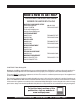
HERE'S HOW TO GET HELP PLEASE HAVE THE MODEL AND SERIAL NUMBER ON-HAND WHEN CALLING MULTIQUIP CORPORATE OFFICE 18910 Wilmington Ave. Carson, CA 90746 Email: mq@multiquip.com Internet: www.multiquip.com PARTS DEPARTMENT 800-427-1244 310-537-3700 MAYCO PARTS 800-306-2926 310-537-3700 SERVICE DEPARTMENT 800-421-1244 310-537-3700 TECHNICAL ASSISTANCE 800-478-1244 WARRANTY DEPARTMENT 800-421-1244, EXT. 279 310-537-3700, EXT.
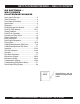
WM-70 PLASTER/MORTAR MIXER — TABLE OF CONTENTS MQ WHITEMAN — WM-70 SERIES PLASTER/MORTAR MIXER Here's How To Get Help .............................................3 Table Of Contents ......................................................4 Parts Ordering Procedures ........................................5 Specifications .............................................................6 Dimensions ................................................................7 Safety Messages Alert Symbols ....................
PARTS ORDERING PROCEDURES When ordering parts, please supply the following information: ❒ ❒ ❒ ❒ ❒ ❒ ❒ Dealer account number Dealer name and address Shipping address (if different than billing address) Return fax number Applicable model number Quantity, part number and description of each part Specify preferred method of shipment: ✓ FedEx or UPS Ground ✓ FedEx or UPS Second Day or Third Day Note: Unless otherwise indicated by customer, all orders are treated as “Standard Orders”, and will ✓ FedEx or UPS Nex
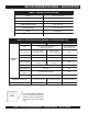
WM-70 PLASTER/MORTAR MIXER — SPECIFICATIONS TABLE 1. MIXER SPECIFICATIONS Capacity 7.0 cu. ft (198 liters) Bag Capacity 1-1/2 to 2-1/2 bags Weight 788 lbs. (357 kg.) Height W/Dump Handle 73 in. (185 cm.) Discharge Height 21 in. (53 cm.) Drive V-Belt/Gear Dump Action Manual TABLE 2. SPECIFICATIONS (ENGINE & ELECTRIC MOTOR) Model Type Engine/Electric Motor HONDA GX160K1HX2 HONDA GX240K1HA2 Air-cooled 4 stroke, Horizontal Shaft Gasoline Engine BALDOR 35L229S302 1.
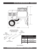
WM-70 PLASTER/MORTAR MIXER — DIMENSIONS TABLE 3. DIMENSIONS Description Dimensions in. (cm) L e n g th (w/ Tow Bar) 67 in. (170 cm) Width 50 in. (127 cm) Height 56 in. (142 cm) Figure 1. Dimensions WM-70 PLASTER/MORTAR MIXER — OPERATION MANUAL — REV.
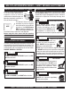
WM-70 PLASTER/MORTAR MIXER — SAFETY MESSAGE ALERT SYMBOLS FOR YOUR SAFETY AND THE SAFETY OF OTHERS! Safety precautions should be followed at all times when operating this equipment. Failure to read and understand the Safety Messages and Operating Instructions could result in injury to yourself and others. This Owner's Manual has been developed to provide complete instructions for the safe and efficient NOTE operation of the MQ Whiteman WM-70 mortar and plaster mixer.
WM-70 PLASTER/MORTAR MIXER — SAFETY MESSAGE ALERT SYMBOLS CAUTION Rotating Parts Hazards NEVER operate equipment with covers, or guards removed. Keep fingers, hands, hair and clothing away from all moving parts to prevent injury. CAUTION CAUTION Equipment Damage Hazards Other important messages are provided throughout this manual to help prevent damage to your light tower, other property, or the surrounding environment.
WM-70 PLASTER/MORTAR MIXER — RULES FOR SAFE OPERATION DANGER Read this manual! Failure to follow instructions in this manual may lead to serious injury or even death! This equipment is to be operated by trained and qualified personnel only! This equipment is for industrial use only. The following safety guidelines should always be used when operating the WM-70 plaster and mortar mixer: GENERAL SAFETY ■ DO NOT operate or service this equipment before reading this entire manual.
WM-70 PLASTER/MORTAR MIXER — RULES FOR SAFE OPERATION ■ ALWAYS stop the engine before servicing, adding fuel and oil. ■ NEVER run engine without air filter. Severe engine may occur. ■ ALWAYS service air cleaner frequently to prevent carburetor malfunction. ■ ALWAYS be sure the operator is familiar with proper safety precautions and operations techniques before using mixer. ■ ALWAYS store equipment properly when it is not being used.
WM-70 PLASTER/MORTAR MIXER — TOWING GUIDELINES Towing Safety Precautions Regularly Inspect Towing Components To reduce the possibility of an accident while transporting the mixer on public roads, always make sure that the mixer towing components and the towing vehicle are in good operating condition and both units are mechanically sound. CAUTION ■ ALWAYS make sure that the fuel valve lever is in the OFF position (gasoline models only). ■ Check wheel mounting lug nuts with a torque wrench.
WM-70 PLASTER/MORTAR MIXER — SAFETY CHAIN CONNECTION CAUTION Always Tow with a Safety Chain NEVER! tow the mixer with the safety chain removed. The safety chain is intended to prevent complete separation of the mixer from the towing vehicle in the event of a tow bar failure. Reference Figure 2 for the installation of the safety chain. Tow Bar to Mixer Connection 2. Route the safety chain through the holes just above the tow bar, located on each side of the mixer stand.
WM-70 PLASTER/MORTAR MIXER — OPERATION AND SAFETY DECALS Machine Safety Decals The MQ Whiteman WM-70 mortar and plaster mixer is equipped with a number of safety decals. These decals are provided for operator safety and maintenance information. Figure 4 below illustrates these decals as they appear on the machine. Should any of these decals become unreadable, replacements can be obtained from your dealer. WARNING ! DCL335 CRUSH HAZARD AREA. KEEP HANDS AND FINGERS CLEAR OF SAFETY GRATE AT ALL TIMES.
WM-70 PLASTER/MORTAR MIXER — GENERAL INFORMATION Application The MQ Whiteman WM-70 series mixers (drum capacity of 7.0 cu. ft./198 liters) are shipped completely assembled and have been factory tested and are ready for use. Ensure that the extension cable is carefully laid out avoiding wet areas, sharp edges and locations where vehicles might run over it. Avoid allowing the extension cable to be trapped underneath the mixer. This mixer is only intended for the production of plaster and mortar.
WM-70 PLASTER/MORTAR MIXER — MAJOR COMPONENTS 7 4 8 9 9. 10 11 12 2 3 10. Safety Grill -Provided for operator safety. This safety grill is designed to keep hands and solid objects out of the mixing drum when in use. This grill should be closed at all times when mixer is in use. DO NOT remove the grill or grill opening bar. Keep the grill clean by washing it down daily. 13 15 14 6 5 16 18 17 1 19 Figure 5.
WM-70 PLASTER/MORTAR MIXER — ENGINE COMPONENTS 5. 6. 7. Fuel Valve Lever – OPEN to let fuel flow, CLOSE to stop the flow of fuel. Choke Lever – Used in the starting of a cold engine, or in cold weather conditions. The choke enriches the fuel mixture. Air Cleaner – Prevents dirt and other debris from entering the fuel system. Remove wing-nut on top of air filter cannister to gain access to filter element. NOTE WARNING Figure 6.
WM-70 PLASTER/MORTAR MIXER — ELECTRIC MOTOR Electric Motor For maintenance care and operation of the electric motor, refer to your electric motor instruction booklet furnished with the motor. Protect the electric motor from dust as much as possible and keep ventilating openings clean. Electric Motor Safety DO NOT spray water at any time on the electric motor. CAUTION TABLE 5.
WM-70 PLASTER/MORTAR MIXER — ELECTRIC MOTOR The motor supplied is wired for 115 VAC grounded operation. Make certain that the correct size grounded (3-wires) extension cord is used. See Table 6. Motors can burn out when the line voltage falls 5% below the voltage rating of the motor. Failure to use proper voltage will cause the motor to overheat and actuate the overload switch. TABLE 6. RECOMMENDED EXTENSION CORD SIZES Model Motor Voltage WM-70 1.5 HP (Electric) 50 ft. 75 ft. (15.24 m) (22.
WM-70 MIXER — PADDLE BLADE ADJUSTMENT (STEEL DRUM) Adjust paddles as shown in Figure 8a. Figure 8a. Paddle Blade Adjustment (Steel Drum) PAGE 20 — WM-70 PLASTER/MORTAR MIXER — OPERATION MANUAL — REV.
WM-70 MIXER — PADDLE BLADE ADJUSTMENT (POLY DRUM) Adjust paddles as shown in Figure 8b. Figure 8b. Paddle Blade Adjustment (Poly Drum) WM-70 PLASTER/MORTAR MIXER — OPERATION MANUAL — REV.
WM-70 PLASTER/MORTAR MIXER — INSPECTION 3. Insert and remove the dipstick without screwing it into Before Starting the filler neck. Check the oil level shown on the dipstick. 1. Read all safety instructions at the beginning of manual. 2. Clean the mixer, removing dirt and dust, particularly the 4. If the oil level is low (Figure 10), fill to the edge of the oil engine cooling air inlet, carburetor and air cleaner. filler hole with the recommended oil type (Table 6). Maximum oil capacity is 2.33 pints (1.
WM-70 PLASTER/MORTAR MIXER — INSPECTION Fuel Check Explosive Fuel Hazard If your mixer has a gasoline engine, determine if the engine fuel is low. If fuel is low, remove the fuel filler cap and fill with unleaded gasoline. Motor fuels are highly flammable and can be dangerous if mishandled. DO NOT smoke while refueling. DO NOT attempt to refuel the mixer if the engine is hot! or running.
WM-70 PLASTER/MORTAR MIXER — START-UP PROCEDURE This section is intended to assist the operator with the initial start-up of the WM-70 mixer (with gasoline engine or electric motor). It is extremely important that this section be read carefully before attempting to use the mixer in the field. DO NOT use your mixer until this section is thoroughly understood. 2. To start a cold engine, move the choke lever (Figure 12) to the CLOSED position.
WM-70 PLASTER/MORTAR MIXER — START-UP PROCEDURE 4. Turn the engine switch (Figure 14) to the ON position. CAUTION Preventing Drum Tipping Make certain the drum lock pin (Figures 17 and 18) is placed to the RIGHT (when viewing the mixer from the towpole end) of the drum stop block which is welded to the front side of the drum. Also make sure lock pin is fully engaged (locked). This will prevent the drum from tipping. Figure 14. Engine ON/OFF Switch 5.
WM-70 PLASTER/MORTAR MIXER — START-UP/SHUT-DOWN PROCEDURES 8. Place the belt slip lever (Figure 20) in the mix position. This will tilt the engine placing tension on the V-belts enabling the shaft to rotate. 4. When charging, mixing, or dumping a batch of plaster or mortar the drum lock pin should be placed to the left (when viewing the mixer from the towpole end) of the drum stop block which is welded to the front side of the drum. See Figure 21. Figure 21. Drum Lock Pin (Left Position) Figure 20.
WM-70 PLASTER/MORTAR MIXER — OPERATION Stopping the Mixer (Gasoline Engine) Stopping the Mixer (Electric Motor) 1. Place the belt slip lever in the start/stop position 1. Place the electric motor's ON/OFF switch (Figure 7) in (Figure 20). the OFF position. 2. Push the main start/stop switch (Figure 15) inward to stop the engine. 2. Disconnect the electric motor's extension cord from its power source. 3. Turn the fuel shut-off valve to the OFF position. 3. 4. Disconnect the spark plug.
WM-70 PLASTER/MORTAR MIXER — MAINTENANCE (ENGINE) Use Table 8 as a general maintenance guideline when servicing your engine. For more detail engine maintenance information, refer to the engine owner's manual supplied with your engine. TABLE 8. ENGINE MAINTENANCE SCHEDULE DESCRIPTION (3) OPERATION BEFORE CHECK X FIRST EVERY MONTH 3 MONTHS OR OR 10 HRS. 25 HRS. EVERY 6 MONTHS OR 5 0 HRS . EVERY Y E AR OR 100 HRS. EVERY 2 YEARS OR 200 HRS.
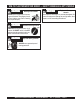
WM-70 PLASTER/MORTAR MIXER — MAINTENANCE (ENGINE) Maintenance ENGINE AIR CLEANER Perform the scheduled maintenance procedures as defined by Table 8 and below: DAILY 1. Remove the air cleaner cover and foam filter element as shown in Figure 25. ■ Thoroughly remove dirt and oil from the engine and control area. Clean or replace the air cleaner elements as necessary. Check and retighten all fasteners as necessary. Check the gearbox for oil leaks. Repair or replace as needed.
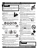
WM-70 PLASTER/MORTAR MIXER — MAINTENANCE (MIXER) Drum Head Seals There is 1 set of drum head seals (Figure 26) that will require lubrication. Lubricate the grease fitting for each drum seal every 40 hours of operation using any grade lithium base grease. Apply grease until visible inside of mixing drum (over grease). This will purge seal system of contamination. GREASE FITTING AND CAP DRUM HEAD SEALS GREASE FITTING AND CAP Ball Socket and Clamp Face Maintenance 1.
WM-70 PLASTER/MORTAR MIXER — MAINTENANCE (MIXER) 2. Fill the wheel hub (Figure 28) with grease to the inside diameter of the outer races and also fill the hub grease cap. Reassemble the hub and mount the wheel. Then tighten the adjusting nut, at the same time turn the wheel in both directions, until there is a slight bind to be sure all the bearing surfaces are in contact.
WM-70 PLASTER/MORTAR MIXER — MAINTENANCE (MIXER) Grease Fittings (Zerk) Maintenance (Electric Motor) Tires Wear/Inflation 1. Tire inflation pressure is the most important factor in tire life. Pressure should be checked cold before operation. DO NOT bleed air from tires when they are hot. Check inflation pressure weekly during use to insure the maximum tire life and tread wear. 2. There are two grease (Figure 33) fittings at each end of the electric motor that will require lubrication.
WM-70 PLASTER/MORTAR MIXER — MAINTENANCE (MIXER) Lug Nut Torque Requirements It is extremely important to apply and maintain proper wheel mounting torque. Be sure to use only the fasteners matched to the cone angle of the wheel. Proper procedure for attachment of the wheels is as follows: 3. After first road use, retorque all lug nuts in sequence. Check all wheel lug nuts periodically. 1. Start all wheel lug nuts by hand. 2. Torque all lug nuts in sequence. See Figure 34.
WM-70 PLASTER/MORTAR MIXER — MAINTENANCE (MIXER) Suspension The rigid type axle and associated hardware (Figure 35) should be periodically inspected for signs of excessive wear, elongation of bolt holes, and loosening of fasteners. Replace all damaged parts immediately. WARNING Keep Hands Clear of Drum! When rotating the mixing drum from the dump position to the upright position, keep hands clear of safety grate. The possibility exists of hands or fingers being crushed (Figure 37). Figure 35.
WM-70 PLASTER/MORTAR MIXER — TROUBLESHOOTING (ENGINE) Practically all breakdowns can be prevented by proper handling and maintenance inspections, but in the event of a breakdown, please take a remedial action following the diagnosis based on the Engine, Mixer and Electric Motor Troubleshooting (Tables 11, 12 and 13) information shown below and on the proceeding pages. If the problem cannot be remedied, please leave the unit just as it is and consult or company's service department. TABLE 11.
WM-70 PLASTER/MORTAR MIXER — TROUBLESHOOTING (ENGINE) TABLE 11. ENGINE TROUBLESHOOTING (CONTINUED) SYMPTOM Insufficient power output "compression" and overheats Burns to much fuel Exhaust color is continiously "WHITE" Exhaust color is continiously "BLACK" POSSIBLE PROBLEM SOLUTION Malfunction in cooling fan? Check or replace cooling fan. Air in-take filter clogged? Clean or replace air in-take filter. Over accumulation of exhaust products? Clean and check valves.
WM-70 PLASTER/MORTAR MIXER —TROUBLESHOOTING (MIXER/ELECTRIC MOTOR) TABLE 12. MIXER TROUBLESHOOTING SYMPTOM POSSIBLE PROBLEM SOLUTION Worn or defective V-belt? Replace V-belt. Adjustment lever mis-aligned? Check position of adjustment lever. Adjust if necessary. Worn or defective paddle shaft seals? Replace seals. Defective or worn drum suppor t brackets? Apply grease to bracket or replace. Blades adjusted too tight. Adjust blades until they almost touch side walls of drum.
WM-70 PLASTER/MORTAR MIXER — WIRING DIAGRAM (ELECTRIC MOTOR) Figure 38. Electric Motor Wiring Diagram PAGE 38 — WM-70 PLASTER/MORTAR MIXER — OPERATION MANUAL — REV.
NOTE PAGE WM-70 PLASTER/MORTAR MIXER — OPERATION MANUAL — REV.
OPERATIONS MANUAL HERE'S HOW TO GET HELP PLEASE HAVE THE MODEL AND SERIAL NUMBER ON-HAND WHEN CALLING MULTIQUIP CORPORATE OFFICE 18910 Wilmington Ave. Carson, CA 90746 Email: mq@multiquip.com Internet: www.multiquip.com PARTS DEPARTMENT 800-427-1244 310-537-3700 MAYCO PARTS 800-306-2926 310-537-3700 SERVICE DEPARTMENT 800-421-1244 310-537-3700 TECHNICAL ASSISTANCE 800-478-1244 WARRANTY DEPARTMENT 800-421-1244, EXT. 279 310-537-3700, EXT.