Operation and Parts Manual SERIES MODELs WM63H5, wm63h8 wm63e plaster and mortar mixer (HONDA GX160UT1HX2/GX240UT1HA2 GASOLINE ENGINES) Revision #0 (09/27/12) To find the latest revision of this publication, visit our website at: www.multiquip.com THIS MANUAL MUST ACCOMPANY THE EQUIPMENT AT ALL TIMES.
Proposition 65 Warning Engine exhaust and some of its constituents, and some dust created by power sanding, sawing, grinding, drillingandotherconstructionactivities contains chemicals known to the State of California to cause cancer, birth defects and other reproductive harm. Some examples of these chemicals are: Leadfromlead-basedpaints. Crystalline silicafrombricks. Cementandothermasonryproducts. Arsenicandchromiumfromchemically treatedlumber.
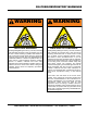
Silicosis/Respiratory Warnings WARNING WARNING SILICOSIS WARNING RESPIRATORY HAZARDS Grinding/cutting/drilling of masonry, concrete, metal and other materials with silica in their composition may give off dust or mists containing crystalline silica. Silica is a basic component of sand, quartz, brick clay, granite and numerous other minerals and rocks. Repeated and/or substantial inhalation of airborne crystalline silica can cause serious or fatal respiratory diseases, including silicosis.
Table of Contents WM63H5/WM63H8/WM63E Plaster And Mortar Mixers Proposition 65 Warning............................................ 2 Silicosis/Respiratory Warnings................................. 3 Table Of Contents..................................................... 4 Parts Ordering Procedures....................................... 5 Safety Information............................................... 6-10 Safety Chain Connection........................................ 11 Specifications...................
www.multiquip.com Parts Ordering Procedures Ordering parts has never been easier! choose from three easy options: order via internet (dealers only): Best deal! Effective: January 1st, 2006 If you have an MQ Account, to obtain a Username and Password, E-mail us at: parts@multiquip. com. Order parts on-line using Multiquip’s SmartEquip website! ■ View Parts Diagrams ■ Order Parts ■ Print Specification Information To obtain an MQ Account, contact your District Sales Manager for more information.
safety information Do not operate or service the equipment before reading the entire manual. Safety precautions should be followed at all times when operating this equipment. Failure to read and understand the safety messages and operating instructions could result in injury to yourself and others. Potential hazards associated with the operation of this equipment will be referenced with hazard symbols which may appear throughout this manual in conjunction with safety messages.
safety information general saFeTY CauTion never operate this equipment without proper protective clothing, shatterproof glasses, respiratory protection, hearing protection, steel-toed boots and other protective devices required by the job or city and state regulations. Avoid wearing jewelry or loose fitting clothes that may snag on the controls or moving parts as this can cause serious injury. never operate this equipment when not feeling well due to fatigue, illness or when under medication.
safety information mixer saFeTY danger never operate the equipment in an explosive atmosphere or near combustible materials. An explosion or fire could result causing severe bodily harm or even death. do noT mix flammable or explosive substances. warning never place your hands inside the drum while starting or operating this equipment. never disconnect any emergency or safety devices. These devices are intended for operator safety.
safety information Fuel saFeTY (gasoline models onlY) danger do noT start the engine near spilled fuel or combustible fluids. Fuel is extremely flammable and its vapors can cause an explosion if ignited. alwaYs refuel in a well-ventilated area, away from sparks and open flames. alwaYs use extreme caution when working with flammable liquids. do noT fill the fuel tank while the engine is running or hot.
safety information Towing saFeTY CauTion Check with your local county or state safety towing regulations, in addition to meeting Department of Transportation (DOT) Safety Towing Regulations, before towing your mixer. In order to reduce the possibility of an accident while transporting the mixer on public roads, alwaYs make sure the towing vehicle is mechanically sound and in good operating condition. environmenTal saFeTY NOTICE Dispose of hazardous waste properly.
safety chain connection CAUTION NEVER tow the mixer with the safety chain removed. The safety chain is intended to prevent complete separation of the mixer from the towing vehicle in the event of a tow bar failure. Tow Bar to Mixer Connection Reference Figure 1 for the installation of the safety chain. 1. Insert the tow bar through the round opening at the bottom of the mixer stand. Align the hole on the tow bar with the hole on the mixer frame, and insert 1/2-inch bolt through tow bar and frame.
specifications Table 1. Mixer Specifications Capacity Bag Capacity Weight Height W/Dump Handle Discharge Height Drive Dump Action Model Type Bore X Stroke Displacement Max Output Fuel Tank Capacity Fuel Lube Oil Capacity Speed Control Method Starting Method Dimensions (L x W x H) Dry Net Weight 6.3 cu. ft (178 liters) 1-1/2 to 2-1/2 bags 574 lbs. (260 kg.) 73 in. (185 cm.) 17.5 in. (44.4 cm.) V-Belt/Gear Manual Table 2.
dimensions C Table 3. Dimensions Description Dimensions in. (cm) Length (w/Tow Bar) 67 in. (170 cm) Width 50 in. (127 cm) Height 56 in. (142 cm) A OPTIONAL TOW BARS APPROXIMATE LENGTH 36 IN. (91.44 CM) HBC-1 2-INCH BALL COUPLER B HPC-1 1-INCH PIN COUPLER HLC-1 LOOP COUPLER Figure 3. Dimensions WM63-series Mixer • operation and parts manual — rev.
general information Application The MQ Whiteman WM63 Series mixers (drum capacity of 6.3 cu. ft./178 liters) are shipped completely assembled and have been factory tested and are ready for use. This mixer is only intended for the production of plaster and mortar. The mixer must be used for its intended purpose and is not suitable for the mixing of flammable or explosive substances. The mixer must not be used in an explosive atmosphere. This mixer has a batch capacity between 2-1/2 and 3-1/2 bags.
components Figure 4 illustrates the basic components and controls of the WM63 Series mixer. 9. Safety Grill — Provided for operator safety. This safety grill is designed to keep hands and solid objects out of the mixing drum when in use. This grill should be closed at all times when mixer is in use. DO NOT remove the grill or grill opening bar. Keep the grill clean by washing it down daily. 10. Dump Handle — Pull this handle downward to dump the contents of the drum.
inspection Before Starting 1. Read all safety instructions at the beginning of manual. 2. Clean the unit, removing dirt and dust, particularly the engine cooling air inlet, carburetor and air cleaner. 5. NOTICE I Reference engine manufacturer’s manual for specific servicing instructions. UPPER LIMIT 3. Check the air filter for dirt and dust. If air filter is dirty, replace air filter with a new one as required. 4. Check carburetor for external dirt and dust. Clean with dry compressed air. 5.
inspection V-belt CHECK Visually examine the V-belt (Figure 7) and determine if it is full of tiny cracks, frayed, has pieces of rubber missing, is peeling or otherwise damaged. Check for worn or defective paddle blades (Figure 9). Make sure that all blades are adjusted properly. See blade adjustment procedure (Figure 13) in this manual. Replace all defective or damaged blades immediately.
basic engine 2. Throttle Lever — Used to adjust engine RPM speed (lever advanced forward SLOW, lever back toward operator FAST). 1 10 9 3. Engine ON/OFF Switch — ON position permits engine starting, OFF position stops engine operations. 2 3 8 4. Recoil Starter (pull rope) — Manual-starting method. Pull the starter grip until resistance is felt, then pull briskly and smoothly. 5. Fuel Valve Lever — OPEN to let fuel flow, CLOSE to stop the flow of fuel. 7 6.
electric motor Electric Motor For maintenance care and operation of the electric motor, refer to your electric motor instruction booklet furnished with the motor. Protect the electric motor from dust as much as possible and keep ventilating openings clean. CAUTION DO NOT spray water at any time on the electric motor. Table 6. Electric Motor Wiring Information 115-230 VAC - Single Phase Motor Horsepower NEMA Mating NEMA Rating Plug Receptacle 1.5 HP L5-20P L5-20R (115 VAC) P/N EM940537 P/N EM940538 1.
electric motor The electric motor supplied is wired for 115 VAC grounded operation. Make certain that the correct size grounded (3-wires) extension cord is used. See Table 7 below. Table 7. Recommended Extension Cord Sizes Model Motor WM63E 1.5 HP Voltage 50 ft. (15.24 m) 75 ft. (22.86 m) 100 ft. (30.48 m) 200 ft. (60.96 m) 115 VAC No. 12 No. 10 No. 8 No. 6 230 VAC No. 14 No. 12 No. 12 No. 8 Motors can burn out when the line voltage falls 10% below the voltage rating of the motor.
paddle blade adjustment Adjust paddles as shown in Figure 13. TOW END CAST PADDLE CENTER TOW END CAST PADDLE DRUM END ENGINE END CAST PADDLE PADDLE BLADE IS TOO TIGHT AGAINST DRUM SIDE WALLS. INCORRECT ROTATION DRUM SIDE END PADDLE BLADE CENTER ENGINE END CAST PADDLE INCORRECT INCORRECT CORRECT CORRECT SIDE PADDLE BLADE ROTATION PADDLE BLADE IS TOO TIGHT AGAINST DRUM SIDE WALLS. DRUM END AND SIDE WALLS Figure 13. Paddle Blade Adjustment WM63-series Mixer • operation and parts manual — rev.
Start-up This section is intended to assist the operator with the initial start-up of the unit. It is extremely important that this section be read carefully before attempting to use the mixer in the field. DO NOT use your mixer until this section is thoroughly understood. 3. Move the throttle lever (Figure 16) away from the slow position, about 1/3 of the way toward the fast position. WARNING Failure to understand the operation of the mixer could result in severe damage to the mixer or personal injury.
start-up 6. Place the belt slip lever (Figure 19) in the START/STOP (disengaged) position. START/STOP POSITION DRUM LATCH PIN STOP BLOCK TOW OR LOCKED POSITION BELT SLIP LEVER Figure 21. Drum Lock Pin (Right Position) 7. Pull the starter grip (Figure 22) lightly until you feel resistance, then pull briskly. Return the starter grip gently. Figure 19.
operation Mixing/Dumping STAND CLEAR OF DUMP HANDLE. HANDLE KICK-BACK IS POSSIBLE. 1. The paddle shaft inside the drum should be rotating at this time. 2. Add a small amount water to the mixing drum. 3. Lift the mixing bag compound onto the steel safety grate over the bag cutter and let the contents fall into the drum. Add more water if desired and mix compound to desired consistency. 4.
notes WM63-series Mixer • operation and parts manual — rev.
maintenance (engine) Use Table 8 as a general maintenance guideline when servicing your engine. For more detail engine maintenance information, refer to the engine owner’s manual supplied with your engine. Table 8.
maintenance (engine) Perform the scheduled maintenance procedures as defined by Table 8 and below: OIL FILLER CAP DIPSTICK DAILY Thoroughly remove dirt and oil from the engine and control area. Clean or replace the air cleaner elements as necessary. Check and retighten all fasteners as necessary. Check the gearbox for oil leaks. Repair or replace as needed. WEEKLY DRAIN SEALING BOLT WASHER Figure 27.
maintenance (Mixer) Drum Head Seals There is 1 set of drum head seals (Figure 29) that will require lubrication. Lubricate the grease fitting for each drum seal every 40 hours of operation using any grade lithium base grease. Apply grease until visible inside of mixing drum (over grease). This will purge seal system of contamination. DRUM BEARING BRACKET Figure 30. Grease Fittings (Dumping Mechanism) CAUTION Figure 29.
maintenance (Mixer) Main Gear and Drive Pinion Alignment GREASE FITTING AND CAP Figure 31. Grease Fittings (Countershaft) Wheel Bearings 1. After every 3 months of operation, remove the hub dust cap and inspect the wheel bearings (Figure 32). Once a year, or when required, disassemble the wheel hubs remove the old grease and repack the bearings forcing grease between rollers, cone and cage with a good grade of high speed wheel bearing grease (never use grease heavier than 265 A.S.T.M. penetration (“No. 2.
maintenance (Mixer) 4. If gear teeth are not contacting properly (Figure 34), adjust pillow block to correct the problem. GREASE FITTING HEAL CONTACT FACE CONTACT TOE CONTACT PROPER CONTACT FLANK CONTACT Figure 34. Gear Teeth Alignment Gear Lubrication The surface of the pinion and main gear (Figure 35) should be very lightly greased. Figure 36. Grease Fittings Electric Motor Tires/Wheels/Lug Nuts Tires and wheels are a very important and critical components of the trailer.
maintenance (Mixer) Table 9. Tire Wear Troubleshooting Wear Pattern Cause Solution Center Wear Adjust pressure to Over Inflation particular load per tire manufacturer Edge Wear Under Inflation Adjust pressure to particular load per tire manufacturer. Side Wear Loss of chamber or overloading Make sure load does not exceed axle rating. Align wheels. Toe Wear Incorrect toe-in Align wheels. Cupping Out of balance Check bearing adjustment and balance tires.
maintenance (Mixer) Suspension ON OFF 2.0 HP 230 SINGLE PHASE 115/230 VAC ELECTRIC MOTOR 115 The rigid type axle and associated hardware (Figure 38) should be periodically inspected for signs of excessive wear, elongation of bolt holes, and loosening of fasteners. Replace all damaged parts immediately. Figure 39. No Spraying of Water WARNING CHECK FOR TIGHTNESS RIGID TYPE AXLE When rotating the mixing drum from the dump position to the upright position, keep hands clear of safety grate.
maintenance (Mixer) Mixer Storage For storage of the mixer for over 30 days, the following is recommended: Drain the fuel tank completely, or add STA-BIL to the fuel. Run the engine until the fuel is completely consumed. Completely drain used oil from the engine crankcase and fill with fresh clean oil, then follow the procedures described in the engine manual for engine storage. Clean the entire mixer and engine compartment. Place the mixing drum in the down position (mouth facing downward).
troubleshooting Troubleshooting (engine) symptom possible problem Spark plug bridging? Check gap, insulation or replace spark plug. Carbon deposit on spark plug? Clean or replace spark plug. Short circuit due to deficient spark plug insulation? Check spark plug insulation, replace if worn. Improper spark plug gap? Set to proper gap. Fuel reaching carburetor? Check fuel line. Water in fuel tank? Flush or replace fuel tank. Fuel filter clogged? Replace fuel filter.
troubleshooting Troubleshooting (engine) - continued symptom Weak in power, compression is proper and does not misfire. Weak in power, compression is proper but misfires. Engine overheats. Rotational speed fluctuates. Recoil starter malfunctions. (if applicable) Starter malfunctions. possible problem Air cleaner dirty? Clean or replace air cleaner. Improper level in carburetor? Check float adjustment, rebuild carburetor. Defective spark plug? Clean or replace spark plug.
troubleshooting Mixer Troubleshooting Worn or defective V-belt? Blades will not rotate. Material leaking from drum ends. Drum difficult to discharge (tilt) Replace V-belt. Check position of adjustment lever. Adjustment lever mis-aligned? Adjust if necessary. Worn or defective paddle shaft seals? Replace seals. Defective or worn drum support Apply grease to bracket or replace. brackets? Adjust blades until they almost touch Blades adjusted too tight. side walls of drum.
wiring diagram WM63-series Mixer • operation and parts manual — rev.
Explanation of Code in Remarks Column The following section explains the different symbols and remarks used in the Parts section of this manual. Use the help numbers found on the back page of the manual if there are any questions. NOTICE The contents and part numbers listed in the parts section are subject to change without notice. Multiquip does not guarantee the availability of the parts listed. sample parTs lisT no. 1 2% 2% 3 4 parT no. parT name QTY. remarks 12345 BOLT .....................1 .....
Suggested Spare Parts Wm63-series plaster and mortar mixer with honda GX160UT1HX2/gx240UT1HA2 engines and 1.5 HP electric motor. 1 to 3 units Qty. P/N Description 6............491107...................V-BELT A32, HONDA ENGINE (GX160, 5.5 HP) 6............07055-034.............V-BELT 4l340, HONDA ENGINE (GX240, 8.0 HP) 6............491112...................V-BELT A40, ELECTRIC MOTOR 2............EM914288.............OIL SEAL, AXLE 4............EM903113.............BEARING, CONE, AXLE 4............EM903012...
nameplate and decals SAFETY INSTRUCTIONS 1. Read owner’s manual before operating. 2. Keep unauthorized and untrained people away from machine during operation. 4 3. Make sure all safety devices are in place before this machine is started. 4. Make sure engine is turned off and spark plug wire is disconnected before cleaning the machine. 5 6 5. Keep hands and fingers away from moving objects. 6. Do not operate machine in an enclosed area, proper ventilation is required. 7.
nameplate and decals NO. PART NO. PART NAME QTY. REMARKS 1 EM948630 decal, push to stop 1 2 521228 decal, do not smoke 1 3 521229 decal, read manual, crush hazard 2 4 515275 DECAL, MQ WHITEMAN LOGO Small 1 5 504714 DECAL, MQ WHITEMAN LOGO Large 1 6 520935 decal, safety instructions 1 7 521230 DECAL, handle kick back, safety grate, crush hazard 1 8 504715 DECAL, WHITEMAN LOGO Large 1 9 521231 decal, drum lock positioning 1 10 nameplate...............................................................
frame assy. MOUNT PILLOW BLOCKS FOR PINION SHAFT HERE MOUNT DRUM BEARING HERE MOUNT DRUM BEARING HERE 3 5 6 4 9 8 2 7 1 11 10 12 15 13 14 CHAIN & LINK KIT 14A A A OPTIONAL TOW BARS 16 17 18 page 42 — wm63-series Mixer • operation and parts manual — rev.
frame assy. NO. PART NO. 1 514842 2 491692 3 530023 4 507444 5 514834 6 530013 7 20278-001 8 EM963692 9 492584 10 514802 11 10176 12 EM124 13$ 14$ 01004 14A$ 516580 15 13363KIT 16 HBC-1 17 HLC-1 18 HPC-1 PART NAME QTY. REMARKS LOCK, PIN 1 COTTER PIN 1 SPRING LOCKING PIN 1 WASHER, FLAT 3/4" 1 MAIN FRAME 1 CLUTCH HANDLE LEVER 1 CLUTCH HANDLE GRIP 1 BOLT 1/2" UNC 1-1/2" 6 NUT, LOCK 1/2" 6 AXLE, UNIVERSAL 1 LOCK NUT 1/2" NC 1 BOLT 1/2"-13 X 4 G5 1 SAFETY CHAIN . ..............................................
paddle shaft assy. page 44 — wm63-series Mixer • operation and parts manual — rev.
paddle shaft assy. NO. 1 2 3 4 5 6 7 8 9 10$ 11$ 12$ 13$ 14$ 15$ 16 17$ 18$ 19 PART NO. 514752 492584 530140C 3215 EM200292 530141 6109170 EM200297 530143 505196 3019092 25667-001 25668-001 1456 0166 A 530142C 33074-001 33017-001 25647-502 PART NAME QTY.
steel tub assy. 24 23 22 20 20 20 29 21 26 25 20 28 27 14 30 15 31 4 11 5 15 12 17 9 4 13 1 13 6 1 3 10 5 9 8 7 6 11 7 3 6 8 10 12 1 2 19 18 18 PART OF REAR FRAME PART OF FRONT FRAME NOTES: SET SCREWS AND BEARING 1 COLLAR ARE INCLUDED WITH BEARING AND CANNOT BE PURCHASED SEPARATELY. page 46 — wm63-series Mixer • operation and parts manual — rev.
steel tub assy. NO. PART NO. 1 530028 2 3249 3 20561-001 4 491008 5 EM916019 6 EM969013 7 3019092 8 514778 9 513453 10 20654-001 11 530029 12 20104-002 13 513452 14 515009 15 492484 16 530043 17 500432 18 17985-012 19 514752 20 6109170 21 515032 22 EM925191 23 514962 24 EM924015 25 6109160 26 6109180 27 EM963692 28 492393 29 492584 30 EM201537 31 15081 PART NAME QTY. REMARKS DRUM BEARING BRACKET 2 CAP, DUST 1 BEARING SEALED.............................................2................
drum and paddle shaft complete assy. page 48 — wm63-series Mixer • operation and parts manual — rev.
drum and paddle shaft complete assy. NO. 1 PART NO. 516069 530028 3249 20561-001 491008 EM916019 EM969013 3019092 514778 07594-012 20654-001 530029 20104-002 513452 515009 EM961019 530043 10057-034 EM963057 514752 6109170 514946 EM924015 6109160 6109180 EM963692 EM201537 15081 514752 492584 530142 3043 EM200292 530141 6109170 EM200297 530143 505196 EM923023 25667-001 25668-001 2105164 EM923343 530140 33074-001 33017-001 PART NAME QTY. REMARKS DRUM AND SHAFT COMPLETE ASSY.............1..........
axle assy. page 50 — wm63-series Mixer • operation and parts manual — rev.
axle assy. NO. 1# 2# 3 4 5 6 7 8# 9# 10# 11 12 PART NO. 3469 29194 516476 8164 EM924008 EM511159 EM501299 EM903113 EM903012 EM914288 EM941306 514802 PART NAME QTY. REMARKS DUST CAP 2 LUG NUTS 8 TIRE AND RIM, TOWMASTER II 2 CASTLE NUT 1-20 JAM 2 COTTER PIN 1/8" X 1-1/2' 2 WASHER, FLAT, .087" THICKNESS 2 WASHER, FLAT, .135" THICKNESS 1 BEARING CONE 4 BEARING CUP 4 OIL SEAL 2 HUB ASSY., 4-BOLT ..........................................2................
engine assy. page 52 — wm63-series Mixer • operation and parts manual — rev.
engine assy. NO. 1 2 3 4 5 6 7 8 9 10 11 12 12 13 14 15 15 16 16 17 18 18 19 20 21 22 22 23 23 24 24 25 26 26 PART NO. EM969013 3019092 EM905016 492378 JISB2804C25 513868 500214 502226 492077 505084 492467 491107 07055-034 503117 508344 2105162 492378 GX160UT1HX2 GX240UT1HA2 514985 492055 505205 604445 530454 530019 EM923023 3019092 EM923343 0166 A 2105164 1456 EM102014 501019 90745ZE2600 PART NAME QTY.
electric motor assy. page 54 — wm63-series Mixer • operation and parts manual — rev.
electric motor assy. NO. 1 2 3 4 8 9 10 11 12 13 14 15 16 17 18 19 20 21 22 23 24 25 26 27 PART NO.
cabinet assy. 2 10 11 2 1 12 2 6 4 3 1 9 8 5 12 OZ. RED SPRAY PAINT 8 7 13 NOTES: 1 COMPLETE LATCH ASSEMBLY INCLUDES ITEMS WITHIN DASHED LINES. ITEMS CANNOT BE PURCHASED SEPARATELY. page 56 — wm63-series Mixer • operation and parts manual — rev.
cabinet assy. NO. 1 2 3$ 4$ 5$ 6$ 7 8 9 10 11 12 13 PART NO. 515014 490202 13287 2203 1307 491010 EM963610 3019092 EM969013 29174-001 29173-001 504135C RAL3020S PART NAME QTY. REMARKS CABINET, ENGINE W/DECALS.........................1................INCLUDES ITEMS W/$ RUBBER PROTECTOR 4 LOCK NUT 8-32 6 WASHER, FLAT #10 6 SCREW PHP 8-32 X 1/2" 6 LATCH ASSY.
terms and conditions of sale — parts paYmenT Terms 5. Parts must be in new and resalable condition, in the original Multiquip package (if any), and with Multiquip part numbers clearly marked. 6. The following items are not returnable: Multiquip reserves the right to quote and sell direct to Government agencies, and to Original Equipment Manufacturer accounts who use our products as integral parts of their own products. a. speCial expediTing serviCe Terms of payment for parts are net 30 days.
notes WM63-series Mixer • operation and parts manual — rev.
Operation and Parts Manual HERE’S HOW TO GET HELP PLEASE HAVE THE MODEL AND SERIAL NUMBER ON-HAND WHEN CALLING United StateS Multiquip Corporate Office 18910 Wilmington Ave. Carson, CA 90746 Contact: mq@multiquip.com MQ Parts Department Tel.