Four USB V.
User Guide 88310952 Revision C MultiModemUSB (Model MT4X56USB) This publication may not be reproduced, in whole or in part, without prior expressed written permission from Multi-Tech Systems, Inc. All rights reserved. Copyright © 1999, by Multi-Tech Systems, Inc. Multi-Tech Systems, Inc. makes no representations or warranties with respect to the contents hereof and specifically disclaims any implied warranties of merchantability or fitness for any particular purpose. Furthermore, Multi-Tech Systems, Inc.
Contents Chapter 1 - Introduction and Description Introduction ....................................................................................................................................................... 6 Features ............................................................................................................................................................ 6 Technical Specifications ......................................................................................................
Loopback Tests ............................................................................................................................................... 60 Local Analog Loopback Test (V.54 Loop 3) ............................................................................................... 61 Remote Digital Loopback Test (V.54 Loop 2) ............................................................................................ 62 Local Digital Loopback Test (V.54 Loop 2) .............................
Four USB V.
MultiModemUSB User Guide Introduction The MultiModemUSB, model MT4X56USB, is a Universal Serial Bus (USB) Concentrator that contains four full-featured V.90 modems and a USB port which allows additional MultiModemUSBs to be daisy-chained together. These features allow any system running Windows 95/98, Windows NT 4.0, or Windows 2000 and equipped with a USB port to quickly and easily add modems four at a time, using MultiModemUSBs, without opening the case.
Chapter 1 - Introduction and Description Technical Specifications The MT4X56USB conforms to the following specifications. USB Ports • Interface: USB Type A and Type B • Speed: up to 12 Mbs Modems • Ports: 4 • Data Rates and Standards: 56 Kbps downloading from V.90/K56flex servers; V.90/K56flex, enhanced V.34, V.32bis, and V.22bis • Error Correction: V.42 • Data Compression: MNP Class 5; V.42bis • Fax Rate and Standards: 14.4 Kbps; V.
MultiModemUSB User Guide Chapter 3 - Software Loading and Configuration This chapter provides the necessary information to verify if your system supports USB and describes the process for installing the appropriate device drivers. Chapter 4 - AT Commands, S-Registers and Result Codes This chapter describes the commands used to control the operation of your modem.
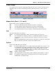
Chapter 1 - Introduction and Description Front Panel The front panel has four groups of LEDs that provide the status of the four port connections, plus a LED that provides the status of Hub activity and and a LED that provides the status of System activity. Figure 1-2. Front Panel Modem Ports (Ports 1, 2, 3, and 4) Modem LEDs are Green and indicate the following: RD The Receive Data indicator blinks when the modem is receiving data.
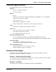
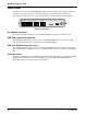
MultiModemUSB User Guide Back Panel The cable connections for the MT4X56USB are made at the back panel. Three groups of cables are used; four ports for RJ-11 modem connections, two types of USB connections, and a power connection. The cable connections are shown in Figure 1-3 and defined in the following groups. Port 1 Port 2 Port 3 Port 4 USB - A USB - B POWER Figure 1-3. Back Panel RJ-ll Modem Connector The four RJ-11 modem connectors connect the MT4X56USB to computers or network servers.
Four USB V.
MultiModemUSB User Guide Unpacking The shipping box contains the MT4X56USB, four RJ-11 cables, one USB cable, an external power supply and cable, your Quick Start Guide, and three disks (i.e., three disks for the MT4X56USB driver software and one disk for the MT4X56USB User Guide). Inspect the contents for signs of any shipping damage. If damage is observed, do not power up the unit; contact Multi-Tech’s Technical Support for advice (refer to Chapter 8).
Chapter 2 - Installation Cabling your MT4X56USB Cabling your MT4X56USB involves making the proper cable and power connections. Figure 2-2 shows the back panel connectors and the associated cable connections. To connect the cables to your MT4X56USB, do the following. 1. Connect the power supply to the MT4X56USB and a live AC outlet. To do this, insert the coaxial plug into the connector marked POWER on the back of the MT4X56USB and plug the AC power input plug into a live AC outlet. 2.
MultiModemUSB User Guide 14 MT4X56USB
Four USB V.
MultiModemUSB User Guide Introduction MT4X56USB software installation consists of verifying that your system supports USB and then installing the appropriate device drivers. Multitech provides the driver software on two diskettes. Disk 1 contains the driver software for Windows 98/95, Disk 2 contains the driver software for Windows NT 4.0, and Disk 3 contains the driver software for Windows 2000. System USB Support Before loading the software you must verify that your system supports USB.
Chapter 3 - Software Loading and Configuration 6. The Add New Hardware Wizard dialog box displays the message “What do you want Windows to do?”. Ensure that the default is enabled (Search for the best driver for your device.) and click Next >. 7. The Add New Hardware Wizard dialog box displays the message “Windows will search for new drivers . . .” Click (check) the box next to “Floppy disk drives” and then click Next >. 8.
MultiModemUSB User Guide 9. The driver files are copied to your Windows System directory. 10. Once the files have been copied to your PC, the Add New Hardware Wizard dialog box is displayed and indicates that Windows has finished installing the software for your hardware device. Click Finish. Several screens are displayed indicating that all software drivers have been successfully installed. Installation is complete when no more screens appear. 11. To install the modems, go to the “Installing Your V.
Chapter 3 - Software Loading and Configuration MT4X56USB Drivers for Windows 95 This section details the process for loading the software. For Windows 95, only version OSR2.1, Revision C, offers support for USB peripherals. If you are unsure that your Windows 95 system supports USB, refer to the “System USB Support” section at the beginning of this chapter. 1. Power up your Windows 95 system. 2.
MultiModemUSB User Guide 6. The Insert Disk dialog box is displayed. Insert MT4X56USB Driver Disk 1 into drive A and click OK. 7. The Copying Files… dialog box is displayed. Type A: in the “Copy files from” field and click OK. The driver files will be copied to your system. 8. Several screens are displayed indicating that ports are being assigned. Installation is complete when the last dialog box disappears. 9. To install the modems, go to the “Installing Your V.90 Modems” section.
Chapter 3 - Software Loading and Configuration MT4X56USB Drivers for Windows NT 4.0 Because NT 4.0 does not support USB, Multi-Tech provides a USB stack that will be installed along with the necessary drivers. To do this, you must have have NT Service Pack 3.00 or higher and an account that has administrative privileges. Note: “Plug-and-Play” operations are not supported in an NT 4.0 (or earlier) operating system. 1. Ensure that power to the MT4X56USB is on but that the USB cable remains disconnected. 2.
MultiModemUSB User Guide 9. After the program files have been copied to your hard drive, the Information dialog box is displayed indicating that the drivers have been successfully installed. Connect the USB cable to the MT4X56USB and click OK. 10. Remove the disk from the floppy drive. 11. Reboot your system. Note: The System LED should be blinking green indicating that the driver software was successfully installed. 12. Once the reboot is completed, the Modem Properties dialog box is displayed.
Chapter 3 - Software Loading and Configuration MT4X56USB Drivers for Windows 2000 This section provides the procedure for loading MT4X56USB driver software in a Windows 2000 operating system. Note: “Plug-and-Play” operations are supported in a Windows 2000 operating system. 1. Power up your Windows 2000 system. 2. Ensure that the appropriate USB cable connection has been made to the peripheral (refer to the “Cabling Your MT4X56USB” section) and that the MT4X56USB is powered on. 3.
MultiModemUSB User Guide 6. The Found New Hardware Wizard dialog box displays the message “Locate Driver Files.” Click (check) the box next to “Floppy disk drives” and then click Next >. 7. Windows locates the driver files on the disk and displays the Add New Hardware Wizard dialog box. Click Next >. 8. Microsoft displays the Digital Signature Not Found dialog box. Click Yes to continue. 9. The driver files are copied to your Windows System directory. 10.
Chapter 3 - Software Loading and Configuration 11. The Found New Hardware Wizard dialog box is displayed. It initiates a second search to create the new COM ports. Follow the instructions on the screen. Click Next >. 12. The Found New Hardware Wizard dialog box displays the message “Install Hardware Device Drivers.” Ensure that the default “Search for the best driver for your device (recommended)” is selected, then click Next >. 13.
MultiModemUSB User Guide 14. The Found New Hardware Wizard dialog box is displayed with the message “Driver Files Search Results.” Click Next >. 15. The Found New Hardware Wizard dialog box is displayed with the message “Windows has finished installing the software for this device.” Click Finish. Several screens are displayed indicating that all software drivers have been successfully installed. Installation is complete when no more screens appear. 16. To install the modems, go to the “Installing Your V.
Chapter 3 - Software Loading and Configuration Installing Your V.90 Modems After the software drivers are installed, you will need to install your V.90 modems. The installation procedures are identical for Windows 95 and Windows 98. The procedure for Windows NT is more involved and differences will be noted below. The procedures for installing your V.90 modems in Windows 2000 are sufficiently different to require a separate installation section.
MultiModemUSB User Guide 3. The Install New Modem dialog box is displayed indicating that Windows NT ( or just “Windows” for Windows 95/98) will now try to detect your modem. READ CAREFULLY! • For Windows 95/98 operating systems, ensure that the “Don’t detect my modem; I will select it” option is NOT enabled (the check box is clear) and click Next >. The modems are automatically detected. Several screens are displayed, then the Verify Modem dialog box is displayed. Go to step 7.
Chapter 3 - Software Loading and Configuration 5. The Install New Modem dialog box is displayed identifying the modem you had selected. Enable the “Selected ports” option and highlight the Communications ports required (e.g., COM5, COM6, COM7, and COM8), then click Next >. 6. The program installs the modems and prompts you to reboot your system and then displays the Install New Modem dialog box. Click Finish. Go to Step 9. 7.
MultiModemUSB User Guide 8. The Install New Modem dialog box is displayed indicating that the modem has been set up successfully. Click Finish. 9. The Modems Properties dialog box is displayed and lists the modems that are set up on the computer. Click Close to exit the program. Note for Windows NT 4.0: Once you have clicked Close, NT requires that you update Dial-up networking (RAS). Click Yes and follow the online instructions.
Chapter 3 - Software Loading and Configuration Installing Your V.90 Modems (Windows 2000) Follow the procedures below to install your V.90 modems in a Windows 2000 operating system. 1. Click Start | Settings | Control Panel | Phone and Modems option. 2. The Location Information dialog box is displayed. Note: This is for first-time instal;lations only. Enter the appropriate location information and click OK. 3. The Phone and Modem Options dialog box is displayed. Click on the Modems tab. Click Add. 4.
MultiModemUSB User Guide 5. The Add/Remove Hardware Wizard dialog box is displayed. Insert Driver Disk 3 into drive A and click Have Disk. 6. The Add/Remove Hardware Wizard dialog box is displayed. Select (highlight) the MultiModem MT4X56USB modem and click Next >. 7. The Add/Remove Hardware Wizard dialog box is displayed. Select (highlight) the COM ports you installed and click Next >. 8. The Microsoft Digital Signature dialog box is displayed. Click Yes to continue.
Chapter 3 - Software Loading and Configuration 9. The Found New hardware Wizard dialog box is displayed. Click Finish. 10. The Phone and Modems Options dialog box is displayed. Check to make certain that all four modems have been installed and then click OK.
MultiModemUSB User Guide Windows 95/98 Configuration Utility The Windows 95 and Windows 98 Configuration utilities are located in your Windows System directory. These utilities allow you to manage various resources of your MT4X56USB.
Chapter 3 - Software Loading and Configuration 3. From the MultiModemUSB USB Properties dialog box, click Version. The Version tab is displayed. The Version tab contains a list of all of the MT4X56USB files, each file's version number, size, date created, and a brief description. 4. From the MultiModemUSB USB Properties dialog box, click Advanced. The Advanced tab is displayed. Click the Uninstall button to remove the MT4X56USB device drivers from your system.
MultiModemUSB User Guide Windows NT 4.0/2000 Configuration Utility The Windows NT 4.0 and Windows 2000 Configuration utilities are located in your Windows System directory. Note: The steps below display Windows NT 4.0 dialog boxes. The Windows 2000 dialog boxes are similar. These utilities allow you to manage various resources of your MT4X56USB.
Chapter 3 - Software Loading and Configuration 3. From the MultiModemUSB USB Properties dialog box, click Version. The Version tab is displayed. The Version tab contains a list of all of the MT4X56USB files, each file's version number, size, date created, and a brief description. 4. To remove the program files, use the Add/Remove program found in the Start menu under Settings | Control Panel. Refer to the “Uninstalling MultiModem USB” section earlier in this chapter.
MultiModemUSB User Guide 38 MT4X56USB
Four USB V.
MultiModemUSB User Guide Introduction The AT commands are used to control the operation of your modem. They are called AT commands because each command must be preceded by the characters AT to get the ATtention of the modem. AT commands can be issued only when the modem is in command mode or online command mode. The modem is in command mode whenever it is not connected to another modem. The modem is in data mode whenever it is connected to another modem and ready to exchange data.
Chapter 4 - AT Commands, S-Registers and Result Codes Command: Bn Values: Default: Description: B0 B1 B2 B3 B15 B16 Communication Standard Setting n = 0–3, 15, 16 1 and 16 Select ITU-T V.22 mode when modem is at 1200 bps. Select Bell 212A when modem is at 1200 bps. Deselect V.23 reverse channel (same as B3). Deselect V.23 reverse channel (same as B2). Select V.21 when the modem is at 300 bps. Select Bell 103J when the modem is at 300 bps.
MultiModemUSB User Guide Command: In Values: Default: Description: I0 I1 I2 I3 I4 I5 I9 I11 Information Request n = 0–5, 9, 11 None Display V.90 protocol supported, modem model, and controller firmware version. Calculate and display ROM checksum (e.g., 12AB). Check ROM and verify the checksum, displaying OK or ERROR. Display V.90 protocol supported, modem model, and controller firmware version. Display firmware version for data pump (e.g., 94).
Chapter 4 - AT Commands, S-Registers and Result Codes Command: T Values: Default: Description: Tone Dialing P, T T Configures the modem for DTMF (touch-tone) dialing. Dialed digits are tone dialed until a P command or dial modifier is received. Command: Vn Values: Default: Description: V0 V1 Result Code Format n = 0 or 1 1 Displays result codes as digits (terse response). Displays result codes as words (verbose response).
MultiModemUSB User Guide Command: &Gn Values: Default: Description: &G0 &G1 &G2 V.22bis Guard Tone Control n = 0, 1, or 2 0 Disable guard tone. Set guard tone to 550 Hz. Set guard tone to 1800 Hz. Note: The &G command is not used in North America. Command: &Jn Values: Default: Description: &J0 &J1 Auxiliary Relay Control n=0 0 The auxiliary relay is never closed. Not supported—responds ERROR.
Chapter 4 - AT Commands, S-Registers and Result Codes Command: &Wn Values: Default: Description: &W0 &W1 Command: &Yn Values: Default: Description: &Y0 &Y1 Store Current Configuration n=0 None Stores current modem settings in nonvolatile memory and causes them to be loaded at power-on or following the ATZ command instead of the factory defaults. See also the &F command.
MultiModemUSB User Guide Command: \Kn Values: Default: Description: Break Control n = 0–5 5 Controls the response of the modem to a break received from the computer, the remote modem, or the \B commnd. The response is different for each of three different states. \K0 \K1 \K2 \K3 \K4 \K5 Data mode. The modem receives the break from the computer: Enter online command mode, no break sent to the remote modem. Clear data buffers and send break to the remote modem. Same as \K0.
Chapter 4 - AT Commands, S-Registers and Result Codes Command: \Vn Values: Default: Description: \V0 \V1 \V2 Protocol Result Code n = 0, 1, or 2 1 Disable the appending of the protocol result code to the DCE speed. Enable the appending of the protocol result code to the DCE speed. Same as \V1. Command: \Xn Values: Defaults: Description: \X0 \X1 XON/XOFF Pass-Through n = 0 or 1 0 Modem responds to and discards XON/XOFF characters. Modem responds to and passes XON/XOFF characters.
MultiModemUSB User Guide Command: +++AT Escape Sequence Values: n/a Description: Puts the modem in command mode (and optionally issues a command) while remaining online. Type +++AT and up to ten command characters, then press ENTER. Used mostly to issue the hang-up command: +++ATH. Command: %%%ATRemote Configuration Escape Sequence Values: n/a Description: Initiates remote configuration mode while online with remote modem. The remote configuration escape character (%) is defined in register S13.
Chapter 4 - AT Commands, S-Registers and Result Codes S-Registers Certain modem values, or parameters, are stored in memory locations called S-registers. Use the S command to read or to alter the contents of S-registers (see previous section).
MultiModemUSB User Guide S38 decimal 0–23 1 S42 decimal 0–1 1 S43 decimal 0–1 1 S48 decimal 7 or 128 7 Sets “downstream” data rate where K56flex provides rates of 32,000 to 56,000 in 2,000 bps increments, V.90 provides rates of 28,000 to 56,000 bps in increments of 1,333 bps. 0 = V.90 disabled K56flex rates 1 = V.
Chapter 4 - AT Commands, S-Registers and Result Codes Result Codes In command mode your modem can send responses called result codes to your computer. Result codes are used by communications programs and can also appear on your monitor.
MultiModemUSB User Guide * EC is added to these result codes when the extended result codes configuration option is enabled. EC is replaced by one of the following codes, depending on the type of error control connection: V42bis —V.42 error control (LAP-M) and V.42bis data compression V42 —V.42 error control (LAP-M) only MNP5 —MNP 4 error control and MNP 5 data compression MNP4 —MNP 4 error control only NoEC —No error control protocol). For more information on scripting, click the Help button.
Four USB V.
MultiModemUSB User Guide Introduction Remote configuration is a network management tool that enables you to configure modems anywhere in your network from one location. With password-protected remote configuration, you can issue AT commands to a remote MT4x56USB for maintenance or troubleshooting as if you were onsite. Remote Configuration Procedure The following steps are valid regardless of whether the connection is established by the local or the remote Multi-Tech modem. 1.
Chapter 5 - Remote Configuration and Management Changing the Remote Escape Character To increase security, you can change a remote modem’s remote configuration escape character. The remote configuration escape character is stored in register S9. The factory default is 37, which is the ASCII code for the percent character (%). Setting S9 to 0 (zero) disables remote configuration entirely—but if you do this remotely, you won’t be able to change it back remotely! 1.
MultiModemUSB User Guide 56 MT4X56USB
Four USB V.
MultiModemUSB User Guide Introduction Your MT4X56USB was thoroughly tested at the factory before it was shipped. If you are unable to make a successful connection with one of the V.90 modem ports, or if you experience data loss or garbled characters during your connection, it is possible that a particular modem is defective. However, it is more likely that the source of your problem lies elsewhere.
Chapter 6 - Troubleshooting • a wrong number • no modem at the other end • a faulty modem, computer, or software at the other end • incompatibility between modems You can narrow the list of possibilities by using extended result codes. Extended result codes are enabled by default. If they have been disabled, enter ATV1X4 and press ENTER while in terminal mode, or include V1X4 in the modem’s initialization string. When you dial again, the modem will report the call’s progress.
MultiModemUSB User Guide • If you have extension phones on the same line as your modem, you or someone else can interrupt the connection by picking up another phone. If this is a frequent problem, disconnect the extension phones before using the modem, or install another phone line especially for the modem. • Check for loose connections between the modem and the computer and the telephone jack.
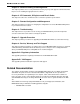
Chapter 6 - Troubleshooting Local Analog Loopback Test (V.54 Loop 3) In this test, data from your computer or terminal is sent to your modem’s transmitter, converted into analog form, looped back to the modem’s receiver, converted into digital form, and then sent to your monitor for verification. No connection to the phone line is required. AT&T1 CONNECT UUUUUUUUU UUU Computer or Terminal Digital Analog Local MultiModemUSB Figure 6-1. Local analog loopback test. Test procedure 1.
MultiModemUSB User Guide Remote Digital Loopback Test (V.54 Loop 2) The remote digital loopback test tests the phone lines and the circuits of both your modem and a remote modem. In this test, your modem must be on line with another modem that is set up to respond to a request for remote digital loopback. (Note that some modems might not support remote digital loopback or might have it disabled.
Chapter 6 - Troubleshooting Local Digital Loopback Test (V.54 Loop 2) The local digital loopback test is identical to the remote digital loopback test with one exception. Instead of using your modem to signal a remote modem to place itself in digital loopback mode, your modem is placed in digital loopback mode while the remote modem is not. Data is entered and transmitted from the remote modem, sent across the phone line to your modem, and looped back to the remote modem.
MultiModemUSB User Guide Windows 95/98 Troubleshooting If after installing the Microsoft USB supplement (usbsupp.exe), Windows Plug-and-Play does not auto-detect the modem, perform the following steps: 1. Open the System icon from the control panel and select the Device Manager Tab. 2. Double-click the Universal Serial Bus Controller icon. 3. Make sure that both the ROOT HUB and HOST Controller are listed. If only the HOST Controller is listed, remove it and reboot. 4.
Four USB V.
MultiModemUSB User Guide Introduction Your modem is controlled by semi-permanent software (firmware) that is stored in flash memory. Firmware is nonvolatile; it remains stored in memory when the modem is turned off. However, it can be changed by either the manufacturer or the user as bugs are fixed or new features are added. Since the firmware in your modem is stored in flash memory, you can upgrade it yourself in a few minutes by using the following procedures.
Chapter 7 - Upgrade Procedure 5. If the Current Revision number is larger than the firmware version number found in “Step 1: Identify the MT4X56USB Firmware,” your MT4X56USB has an older firmware version. Continue with “Step 3: Download the Upgrade File.” Step 3: Download the Upgrade File Multi-Tech Web Site 1. If you are not already at the Firmware page of the Multi-Tech Web site, follow the procedure in “Step 2: Identify the Current Firmware.” 2.
MultiModemUSB User Guide Step 6: Upgrade the Modem’s Firmware At various times, Multi-Tech may add enhancements and/or fixes to the modem firmware. Flash technology allows you to load these upgrades into the PROM. Do the following. 1. Download FLASHPRO.ZIP and a new .HEX file from the Multi-Tech FTP or Web site. 2. Unzip the FLASHPRO.ZIP file. Place this unzipped file and the .HEX file in the same directory. 3. Run FlashPro by typing FLASHPRO, a space, and hitting ENTER at the DOS prompt. 4.
Four USB V.
MultiModemUSB User Guide Introduction This chapter provides the information necessary for receiving service or support for your MT4X56USB. The chapter includes Multi-Tech’s license agreement, a description of the warranty, and provides instructions for contacting the Service Department, Technical Support group, and various Multi-Tech internet resources. Software User License Agreement MultiMobileUSB software is licensed by Multi-Tech Systems, Inc.
Chapter 8 - Service, Warranty and Tech Support Limited Warranty Multi-Tech Systems, Inc. (“MTS”) warrants that its products will be free from defects in material or workmanship for a period of two years from the date of purchase, or if proof of purchase is not provided, two years from date of shipment. MTS MAKES NO OTHER WARRANTY, EXPRESSED OR IMPLIED, AND ALL IMPLIED WARRANTIES OF MERCHANTABILITY AND FITNESS FOR A PARTICULAR PURPOSE ARE HEREBY DISCLAIMED.
MultiModemUSB User Guide Contacting Tech Support via E-mail If you prefer to receive service on-line, via the internet, you can contact Tech Support via e-mail at the following address: http://www.multitech.com/ Service If your tech support specialist decides that service is required, your MT4X56USB may be sent (freight prepaid) to our factory. Return shipping charges will be paid by Multi-Tech Systems.
Four USB V.
MultiModemUSB User Guide Appendix A - Regulatory Information Class B Statement FCC Part 15 This equipment has been tested and found to comply with the limits for a Class B digital device, pursuant to Part 15 of the FCC Rules. These limits are designed to provide reasonable protection against harmful interference in a residential installation.
Appendices FCC Part 68 Telecom 1. This equipment complies with Part 68 of the Federal Communications Commission (FCC) rules. On the outside surface of this equipment is a label that contains, among other information, the FCC registration number and ringer equivalence number (REN). If requested, this information must be provided to the telephone company. 2. As indicated below, the suitable jack (Universal Service Order Code connecting arrangement) for this equipment is shown.
MultiModemUSB User Guide FAX Branding Statement The Telephone Consumer Protection Act of 1991 makes it unlawful for any person to use a computer or other electronic device, including fax machines, to send any message unless such message clearly contains the following information: • Date and time the message is sent • Identification of the business or other entity, or other individual sending the message • Telephone number of the sending machine or such business, other entity, or individual This infor
Appendices EMC, Safety and Terminal Directive Compliance The CE mark is affixed to this product to confirm compliance with the following European Community Directives: Council Directive 89/336/EEC of 3 May 1989 on the approximation of the laws of Member States relating to electromagnetic compatibility.
MultiModemUSB User Guide Appendix B - V.90 Support Introduction V.90 is the ITU designation for what had formerly been called V.pcm. The ITU recommendation V.90 was determined at a meeting in Geneva ending February 6, 1998. V.90 will replace K56flex and other proprietary solutions for PCM connections. Dual-mode client modem code will be important until all central-site digital modems are upgraded to V.90 and all interoperability problems have been resolved.
Four USB V.
MultiModemUSB User Guide A Analog signal: A waveform which has amplitude, frequency and phase, and which takes on a range of values between its maximum and minimum points. Analog Transmission: One of two types of telecommunications which uses an analog signal as a carrier of voice, data, video, etc. An analog signal becomes a carrier when it is modulated by altering its phase, amplitude and frequency to correspond with the source signal. Compare with digital transmission.
Glossary Bus Enumeration: Detecting and identifying Universal Serial Bus devices. Byte: The unit of information a computer can handle at one time. The most common understanding is that a byte consists of 8 binary digits (bits), because that’s what computers can handle. A byte holds the equivalent of a single character (such as the letter A). C Call Setup Time: The time to establish a circuit-switched call between two points. Includes dialing, wait time, and CO/long distance service movement time.
MultiModemUSB User Guide Congestion: A network condition where there is too much data traffic. The ITU I.233 standard defines congestion managemennt in terms of speed and burstiness. Congestion notification: The function in frame relay that ensures that user data transmitted at a rate higher than the CIR are allowed to slow down to the rate of the available network bandwidth.
Glossary Digital Signal: A discrete or discontinuous signal (e.g., a sequence of voltage pulses). Digital devices, such as terminals and computers, transmit data as a series of electrical pulses which have discrete jumps rather than gradual changes. Digital Signaling Rates (DSn): A hierarchical system for transmission rates, where “DS0” is 64 Kbps (equivalent to ISDN B channel), and DS1 is 1.5 Mbps (equivalent to ISDN PRI).
MultiModemUSB User Guide Extended Super Frame (ESF): One of two popular formats for framing bits on a T1 line. ESF framing has a 24-frame super-frame, where robbed bit signaling is inserted in the LSB (bit 8 of the DS-0 byte) of frames 6, 12, 18 and 24. ESF has more T1 error measurement capabilities than D4 framing. Both ESF and B8ZS are typically offered to provide clear channel service. F Failed Seconds: A test parameter where the circuit is unavailable for one full second.
Glossary Host Controller: The host’s Universal Serial Bus interface. A hardware device that provides the interface to the Host Controller Driver (HCD) and the USB bus. Host Controller Driver (HCD): Software that provides an interface to the USB Driver and the Host Controller. (The interface to the Host Controller is defined by the OHCI spec. I Implicit congestion management: A method of informing the terminal that the network is busy.
MultiModemUSB User Guide L LAPB: Link Access Procedure Balanced; based on the X.25 Layer 2 specification. A full-duplex, point-to-point, bitsynchronous protocol commonly used as a data link control protocol to interface X.25 DTEs. LAPB is the link initialization procedure that establishes and maintains communications between the DTE and the DCE. LAPD: Link Access Protocol for the D-Channel; based on the ISDN Q.921 specification.
Glossary Multiplexer (Mux): 1. A device that takes several input signals and combines them into a single output signal in such a manner that each of the input signals can be recovered. 2. A device capable of interleaving the events of two or more activities or capable of distributing the events of an interleaved sequence to the respective activities. 3. Putting multiple signals on a single channel. Multiprotocol: A device that can interoperate with devices utilizing different network protocols.
MultiModemUSB User Guide Packet Mode: Refers to the switching of chunks of information for different users using statistical multiplexing to send them over the same transmission facility. Parity bit: An extra bit attached to each byte of synchronous data used to detect errors in transmission. Permanent Virtual Circuit (PVC): A connection between two endpoints dedicated to a single user. In ISDN, PVCs are establised by network administration and are held for as long as the user subscribes to the service.
Glossary Rate Enforcement: The concept in frame relay where frames sent faster than the CIR are to be carried only if the bandwidth is available, otherwise they are to be discarded. (The frame relay network assumes that anything exceeding the CIR is of low priority.) Rate enforcement makes sure that the network will not get so congested that it isn’t able to meet the agreed on CIR.
MultiModemUSB User Guide Synchronous Data Link Control (SDLC): A discipline conforming to subsets of the Advanced Data Communications Control Procedures (ADCCP) of the American National Standards Institute (ANSI) and High-level Data Link Control (HDLC) of the International Organization for Standardization, for managing synchronous, code-transparent, serial-by-bit information transfer over a link connection. Transmission exchanges may be duplex, or half-duplex over switched or nonswitched links.
Glossary Transmission Control Protocol (TCP): A communications protocol used in Internet and in any network that follows the US Department of Defense standards for internetwork protocol. TCP provides a reliable host-to-host protocol between hosts in packet-switched communications networks and in interconnected systems of such networks. It assumes that the Internet protocol is the underlying protocol.
MultiModemUSB User Guide USB: See Universal Serial Bus. USBD: See Universal Serial Bus Driver. USB Performance categories: Low Speed (Interactive Devices at 10-100 Kb/s); Medium Speed (Phone, Audio, Compressed Video at 500Kb/s - 10Mbp/s); High Speed (Video, Disk at 25-500 Mb/s) V V.25bis: An ITU-T standard for synchronous communications between a mainframe or host and a modem using HDLC or other character-oriented protocol. V.
Index Index Symbols 56K operation digital loss when used with PBX ........................ 50 disabling the auto rate ....................................... 50 A Abort timer ............................................................. 49 Analog loopback test ............................................. 61 Answer command ................................................. 40 Asynchronous Communications Mode command . 44 AT Command Control command ........................... 47 AT commands ................
MultiModemUSB User Guide Commission Decision "CTR21" ............................. 77 Communication Standard command ..................... 41 Communications Mode command ......................... 44 Communications programs ............................ 40, 58 Configuration selecting reset configuration .............................. 45 storing ................................................................ 45 Configuration utility For Windows 95/98 ............................................
Index For Windows 95 ................................................. 19 For Windows 98 ................................................. 16 For Windows NT 4.0 .......................................... 21 Local analog loopback test .................................... 61 Local digital loopback test ..................................... 63 Loopback tests ...................................................... 60 Local Analog (V.54 Loop 3) ................................ 61 Local digital (V.54 loop 2) .....
MultiModemUSB User Guide Select Maximum MNP Block Size command ........ 45 Select Stored Configuration command .................. 45 Service .................................................................. 72 Set Register Value command ................................ 42 Setup password .................................................... 54 Shipping information .............................................. 72 Software user license agreement .......................... 70 Speed maximum ....................