
User guide

Chapter 2 - Installation
MT4X56USB 13
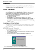
Cabling your MT4X56USB
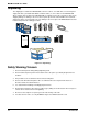
Cabling your MT4X56USB involves making the proper cable and power connections. Figure 2-2
shows the back panel connectors and the associated cable connections. To connect the cables to your
MT4X56USB, do the following.
1. Connect the power supply to the MT4X56USB and a live AC outlet. To do this, insert the coaxial
plug into the connector marked POWER on the back of the MT4X56USB and plug the AC power
input plug into a live AC outlet.
2. Connect one end of the RJ-11 cable to Port 1 on the back of the MT4X56USB. Connect the other
end to the line jack which provides access to the public phone system.
Repeat step 2 for up to four connections (Port 1 - Port 4).
3. Use the provided MT4X56USB cable to make either an “Upstream” or a “Downstream”
Connection.
Upstream Connection: connect the flat (4-pin) end of the MT4X56USB cable to the connector
marked USB - A on the back of your MT4X56USB. Connect the “D-shaped” end to the
“Upstream” device (Hub input or additional MT4X56USBs).
Downstream Connection: connect the flat (4-pin) end of the MT4X56USB cable to the
“Downstream” device (USB-supported peripheral such as a computer, printer, scanner, modem,
or output Hub). Connect the “D-shaped” end to the connector marked USB - B on the back of
your MT4X56USB.
CAUTION: Do NOT plug the “D-shaped” end of the USB cable into the USB-B port on the back
of your MT4X56USB at this time.
Power Connection
Port Connections
USB - A
POWER
USB - B
Port 1 Port 2
Port 4
Port 3
“Upstream Connection”
Hubs (Input) or additional
MT4X56USBs
“Downstream Connection”
Peripherals such as
computers, printers,
scanners, modems, or hubs
PSTN (Public Switched
Telephone Network) Connections
RD
RD
TD CD
TD CD
TR
TR
Port 1
Port 1
RD
RD
TD CD
TD CD
TR
TR
Port 2
Port 2
RD
RD
TD CD
TD CD
TR
TR
Port 3
Port 3
RD
RD
TD CD
TD CD
TR
TR
Port 4
Port 4
Four USB V.90 Modems
Hub
System
®
Figure 2-2. Back Panel Connections