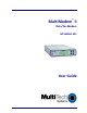
® MultiModem II Data/Fax Modem MT5600BA-V92 User Guide
Copyright and Technical Support MultiModem II User Guide MT5600BA–V92 S000408H Copyright All rights reserved. This publication may not be reproduced. Copyright © 2006-9 by Multi-Tech Systems, Inc. Multi-Tech Systems, Inc. makes no representations or warranties with respect to the contents hereof and specifically disclaims any implied warranties of merchantability or fitness for any particular purpose. Furthermore, Multi-Tech Systems, Inc.
Contents Chapter 1 – Description and Features .................................................................................................5 Product Description .....................................................................................................................5 Analog Telecom Safety Warnings .................................................................................................5 AT Commands and Fax Developer Guides .............................................................
Modem Disconnects While Online .............................................................................................. 41 Modem Cannot Connect When Answering.................................................................................. 42 File Transfer is Slower Than It Should Be..................................................................................... 42 Data is Being Lost .................................................................................................................
Chapter 3 – Using the Front Panel Chapter 1 – Description and Features Product Description This modem supports two- and/or four-wire leased lines. The four-wire leased line includes the dial backup and automatic leased line restoration features. The MultiModem II offers interactive automatic dialing. You can store four command lines or telephone numbers in the modem’s nonvolatile memory. The modem pulse- or tone-dials and recognizes dial tones and busy signals for reliable call-progress detection.
Chapter 3 – Using the Front Panel ATTENTION: Pour réduire les risques d’incendie, utiliser uniquement des conducteurs de télécommunications 26 AWG au de section supérleure. AT Commands and Fax Developer Guides AT Commands and Fax Class 1 and Class 2 Developer Guides for this product are published in separate documents. You can download these from the Multi-Tech Installation Resources website at www.multitech.com/setup/product.go.
Chapter 3 – Using the Front Panel Operating Temperature1 Humidity Range Storage Temperature Power Requirement Power Supply Requirement: 32°–120° F (0°–50° C) ambient under closed conditions UL Listed at 40°C 25–85% (non-condensing) 14°– 185° F (-10° to +85° C) 9 to 12Vdc @ 650mA Listed ITE power supply, marked “LPS” or “Class II”, output rated: 9 to 12Vdc, 650mA Dimensions Weight Limited Warranty Certifications 6.2" wide × 1.4” high x 9.0" deep (15.8 cm × 3.6 cm x 22.9 cm) 2 lbs. (0.
Chapter 3 – Using the Front Panel Chapter 2 - Installation Connecting the Modem to Your System 1. Turn off your computer. PHONE LINE LEASED MultiModem II Connections 2. Connect the modem to your PC: a. Plug one end of the serial cable into the modem’s RS-232 connector. b. Plug the other end into your PC’s serial port connector (COM1 or COM2). 3. Connect the modem to the telephone line (dialup connection): a. Plug one end of the phone cable into the modem’s LINE jack. b.
Chapter 3 – Using the Front Panel 5. Connect the phone to the modem (optional). For voice-only calls, plug a telephone into the modem’s PHONE jack. 6. Connect the modem to the AC power outlet: a. Plug the power supply into an AC power outlet or power strip. b. Plug the power supply’s cable into the POWER jack on the modem. Note: 7. Use only the power supply supplied with the modem. Use of any other transformer voids the warranty and can damage the modem.
Chapter 3 – Using the Front Panel 12. Setting Your Country or Region Code You must configure your modem to match the defaults of the country or region in which you are using it. Choose from any of the three methods: ● ● ● Using the LCD Panel Using the Global Wizard Using AT Commands Finding Country or Region Codes To find the country or region codes for your device: 1. Go to http://www.multitech.com/PRODUCTS/Info/approvals and click on global modems. 2.
Chapter 3 – Using the Front Panel Using AT Commands You can use AT commands to configure your modem through a communication program’s terminal window. How to Change the Country/Region Code 1. View the list of available country/region codes to find your country/region code by executing the command AT +GCI? Note: 2. A list of country/region codes is also available on the Multi-Tech Web site. Refer to Finding Country or Region Codes for details.
Chapter 3 – Using the Front Panel Chapter 3 - Using the Front Panel Like any modem, your Multi-Tech modem operates under the control of a communication program. You can use general-purpose data communication programs, such as Windows Terminal and HyperTerminal. For information on how to use the modem with the communication program of your choice, please refer to the program’s documentation.
Chapter 3 – Using the Front Panel Liquid Crystal Display (LCD) The modem’s backlit liquid crystal display (LCD) has two functions: to display the current status of the modem and to display configuration menus, which are selected using the four push buttons on the front panel. Option Selection To select most configuration options, display the option in the LCD, and press Enter to select it. An OPTION SET message appears to confirm the selection. To clear OPTION SET, press any button.
Chapter 3 – Using the Front Panel Status Status shows the modem’s current operating status. Limb changes are automatic, but certain options can be accessed by pressing . Note that when the modem is online, pressing shows the connect status, including data speed, connection type, and compression type. 4 Multi-Tech Systems, Inc.
Chapter 3 – Using the Front Panel Basic Options Use Basic Options to configure the modem’s basic operating conditions. Multi-Tech Systems, Inc.
Chapter 3 – Using the Front Panel Multi-Tech Systems, Inc.
Chapter 3 – Using the Front Panel Advanced Options Use Advanced Options to configure RS-232, dial backup, and callback security options. Note: New LED for Linux (&C6) Available Here Multi-Tech Systems, Inc.
Chapter 3 – Using the Front Panel Remote Configuration Options Use Remote Configuration Options to enable or disable remote configuration on the modem and to change the password. Diagnostic Options Use the Diagnostic Options Trunk to run loopback tests on the modem. When a test is in progress, the TM indicator lights. Note: Digital Loopback and Remote Digital Loopback tests must be performed using AT Commands. The LCD option to run these tests has been temporarily removed. Multi-Tech Systems, Inc.
Chapter 3 – Using the Front Panel Phone Number Memory Options MultiModem II stores up to four telephone numbers for speed dialing. Use Phone Number Memory Options to store, list, and dial these numbers. Caller ID Options Trunk Use the Caller ID Options Trunk to enable or disable Caller ID operation. Important: #CID displays as +VCID Setting Country/Region Codes 1. Start at the Status LCD and use the down arrow to move through the menu to the Region Select LCD. 2.
Chapter 3 – Using the Front Panel Key LCD Options This section describes important LCD options. Many options have AT command equivalents. Status Options Status LCDs display the current status of the modem. Though limb changes are automatic, certain options can be selected by pressing the button. STATUS = IDLE The modem is ready but inactive. This LCD appears when the modem is first turned on, and is the starting point for accessing all other LCDs.
Chapter 3 – Using the Front Panel Basic Options The following LCDs are used to configure the modem’s basic operating conditions. ONLINE OPTIONS The following LCDs are used to configure the online operation of the modem: LINE TYPE OPTIONS Use and Enter to select from the following line types: dial-up (PSTN), two-wire leased line originate or answer, and four-wire leased line originate or answer.
Chapter 3 – Using the Front Panel COMMAND MODE The following LCDs are used to configure result code responses. OPTIONS ENABLE/DISABLE Use and Enter to enable or disable the sending RESPONSE of result codes to the computer. Same as the Q0 and Q1 commands. VERBOSE/TERSE RESPONSE Use and Enter to select verbose or terse result codes. Same as the V0 and V1 commands. ENABLE/DISABLE CMD Use and Enter to enable or disable the modem’s MODE ability to accept AT commands.
Chapter 3 – Using the Front Panel Advanced Options RS232 OPTIONS DIALBACKUP/LL OPTIONS The following LCDs are used to configure the RS-232 interface. DTR OPTIONS Use and Enter to select how the modem responds to the high to low transition of the DTR signal sent by the computer. DTR NORMAL causes the modem to hang up; IGNORE DTR allows operation with computers that do not provide DTR; and RESET ON DTR causes the modem to perform a soft reset as if the Z command were received.
Chapter 3 – Using the Front Panel CALLBACK SECURITY Use and Enter to turn callback security on or off. Same as the #DB0 and #DB1 commands. For more information about callback security, see Chapter 6, “Callback Security.” PASSWORD SETUP Use to enter callback security passwords in memory locations 1–30. Each password must be six to ten characters in length. To scroll through a list of digits and characters, press and . To go to the next position, press .
Chapter 3 – Using the Front Panel Remote Configuration Options The following LCDs are used to configure remote configuration options. For more information about remote configuration, see Chapter 5, “Remote Configuration.” ENABLE/DISABLE R.C Use and Enter to turn remote configuration on or off. REMOTE CONFIG. PASSWORD Use to enter the remote configuration password. To scroll through a list of digits and characters, press and . To go to the next position, press .
Chapter 3 – Using the Front Panel Multi-Tech Systems, Inc.
Chapter 4 – Leased Line Operation Chapter 4 - Leased Line Operation This chapter describes how to use the MultiModem II modem on a leased line. A leased line is a private, permanent, telephone connection between two points. Unlike dialup connections, a leased line is always active. The modems automatically connect when they are attached to the line and are turned on.
Chapter 4 – Leased Line Operation Four-Wire Setup For four-wire leased line operation: 1. Connect one end of the four-wire cable to the LEASED jack on the back of the modem. Connect the other end of the cable to a four-wire leased line jack or terminals. 2. Turn on the modem. 3. Starting at the STATUS LCD, press the following buttons on the front panel: , , , , , , , , . The SYNC, NORM? LCD appears. 4. Press Enter to select normal synchronous operation. The OPTION SET LCD appears. 5.
Chapter 4 – Leased Line Operation Dial Backup and Leased Line Restore Setup 1. Connect a telephone cable to the LINE jack of an MT5600BA-V92 modem set up for leased line operation. Connect the other end of the cable to a standard dialup line jack. 2. Turn on the modem. 3. Starting at the STATUS LCD, press the following buttons on the front panel: , , , , , , . The ENTER NUMBER LCD appears. 4. Press or several times to select the first digit in the dial backup telephone number. 5.
Chapter 5 – Remote Configuration Chapter 5 - Remote Configuration Remote configuration is a tool that allows you to configure modems anywhere in your network from one location. With password-protected remote configuration, you can issue AT commands to a remote MultiModem II modem for maintenance or troubleshooting as if you were on-site. Basic Procedure The following steps are valid regardless of whether the connection is established by the local or the remote MultiModem II modem. 1.
Chapter 5 – Remote Configuration Changing the Remote Escape Character To improve security, you can change a remote modem’s remote configuration escape character. The remote configuration escape character is stored in register S13. The factory default is 42, which is the ASCII code for the asterisk character (*). Setting S13 to 0 (zero) disables remote configuration entirely— but if you do this remotely, you won’t be able to change it back remotely! 1.
Chapter 6 – Callback Security Chapter 6 - Callback Security This chapter describes how to use callback security with your modem. Callback security protects your network from unauthorized access and helps control long distance costs. When callback security is enabled, all callers are requested to enter a password. If the password is invalid, the caller can try twice more before the modem hangs up.
Chapter 6 – Callback Security ● ● To turn on callback security, press , , , , , , to display the CALLBACK ON? option, and then press the Enter button to select the option. When remote callback security is turned on, each caller is asked to enter a password, then is disconnected and called back by the modem. Also, dialing number locations 0–3, for use with the DS=y dialing command, are replaced by callback dialing number locations 1–30.
Chapter 6 – Callback Security AT Command Method 1. Open a data communication program, such as HyperTerminal. 2. To store a callback phone number in the first memory location, type AT#CBN01=xxxxxxxxxx, where xxxxxxxxxx is the dialing string, and press Enter. The dialing string can include the digits 0 through 9 and any of the following characters: #, *, comma (,), semicolon (;), W, A, B, C, and D. Up to 30 characters can be used. Example: AT#CBN01=9,16127853000.
Chapter 6 – Callback Security Calling Procedure Use the following procedure to call a modem that has callback security enabled. Autoanswer must be enabled on the calling modem (S0=1 or S0=2). 1. Using a data communication program such as HyperTerminal, dial the number of the callback modem. When the connection is established, the callback modem responds with a request for a password. 2. Type the password for your modem, and then press ENTER.
Chapter 6 – Callback Security Store Callback Number Command: Values: Default: Description: #CBNy=[-]x y = 01–30 x = dialing string None Stores the callback dialing string x in memory location y. The dialing string can include the digits 0 through 9 and any of the following characters: #, *, comma (,), semicolon (;), W, A, B, C, and D. Up to 30 characters can be used. Example: AT#CBN01=9,16127853000.
Chapter 7 – Installing on Linux Chapter 7 - Installing on Linux This chapter explains how to install a modem on a computer operating under the Red Hat Linux 6.2 operating system. Other versions of Red Hat and other Linux operating systems should be similar. With Linux, you do not need drivers for most standard external modems and most internal ISA bus modems. Programs in Linux commonly call upon the port, rather than the modem.
Chapter 7 – Installing on Linux 2. Select Internet from the menu. 3. Select Dialup Configuration Tool. 4. Select Add, and then click Next. 5. Enter the connection name and phone number, and then click Next. 6. Enter your user name and password, and then click Next. 7. Select Normal ISP if your ISP is not listed, and then click Next. 8. Click Finish. Calling the ISP 1. On the Task Bar at the bottom of the LCD, select the Gnome Footprint. 2. Select Internet from the menu. 3.
Chapter 8– Troubleshooting Chapter 8 - Troubleshooting Your modem was thoroughly tested at the factory before it was shipped. If you are unable to make a successful connection or if you experience data loss or garbled characters during your connection, it is possible that the modem is defective. However, it is more likely that the source of your problem lies elsewhere. The following symptoms are typical of problems you might encounter: ● None of the LEDs light when the modem is on.
Chapter 8– Troubleshooting Modem Does Not Respond to Commands ● Make sure the modem is plugged in and turned on. (See “None of the Indicators Light.”) ● Make sure you are issuing the modem commands from data communication software, either manually in terminal mode or automatically by configuring the software. ● Make sure you are in terminal mode in your data communication program, then type AT and press ENTER.
Chapter 8– Troubleshooting ● If the modem reports NO DIALTONE, check that the modem’s telephone line cable is connected to both the modem’s LINE jack (not the PHONE jack) and the telephone wall jack. If the cable looks secure, try replacing it. If that doesn’t work, the problem might be in your building’s telephone installation. To test the building installation, plug a telephone into your modem’s telephone wall jack and listen for a dial tone.
Chapter 8– Troubleshooting Modem Cannot Connect When Answering ● The default DTR Control command (&D2) inhibits autoanswer. To enable autoanswer, change DTR Control to &D0, and make sure &Q0, &Q1, &Q5, or &Q6 is also set. For more information, see the &D command in the AT Command Reference Guide on the CD shipped with your modem. For information on changing the modem’s default configuration, see “Step 3: Install and Configure Your Software” in Chapter 2. ● Autoanswer might be disabled.
Chapter 8– Troubleshooting ● Try entering the &V1 command to display information about the last connection, making a LCD print of the connection statistics, and checking for parameters that might be unacceptable. Modem Doesn’t Work with Caller ID ● Caller ID information is transmitted between the first and second rings, so if autoanswer is turned off (S0=0) or if the modem is set to answer after only one ring (S0=1), the modem will not receive Caller ID information.
Appendix A –Regulatory Information Appendix A - Regulatory Information FCC Part 68 Telecom 1. This equipment complies with Part 68 of the 47 CFR rules and the requirements adopted by the ACTA. Located on this equipment is a label that contains, among other information, the registration number and Ringer Equivalence Number (REN) for this equipment or a product identifier in the format: For current products: US:AAAEQ##Txxxx. For legacy products: AU7USA-xxxxx-xx-x.
Appendix A –Regulatory Information 10. Connection to party line service is subject to state tariffs. Contact the state public utility commission, public service commission or corporation commission for information. 11. This equipment is hearing aid compatible. 12. Manufacturing Information on telecommunications device (modem): Manufacturer: Multi-Tech Systems, Inc. Trade Name MultiModem II Model Number: MT5600BA FCC Registration No: AU7USA-33378-M5-E Ringer Equivalence No: 0.
Appendix A –Regulatory Information Le présent appareil est conforme aux CNR d'Industrie Canada applicables aux appareils radio exempts de licence. L'exploitation est autorisée aux deux conditions suivantes: 1. l'appareil ne doit pas produire de brouillage, et 2. l'utilisateur de l'appareil doit accepter tout brouillage radioélectrique subi, même si le brouillage est susceptible d'en compromettre le fonctionnement.
Appendix A –Regulatory Information New Zealand Telecom Warning Notice 1. The grant of a Telepermit for any item of terminal equipment indicates only that Telecom has accepted that the item complies with minimum conditions for connection to its network. It indicates no endorsement of the product by Telecom, nor does it provide any sort of warranty.
Appendix A –Regulatory Information International Modem Restrictions Some dialing and answering defaults and restrictions may vary for international modems. Changing settings may cause a modem to become non-compliant with national telecom requirements in specific countries. Also note that some software packages may have features or lack restrictions that may cause the modem to become non-compliant. Russian Statement MT5600BA is Russia approved, Declaration of Conformity # Д-ТФ-0705 valid till 20.02.
Appendix A –Regulatory Information Restriction of the Use of Hazardous Substances (RoHS) Multi-Tech Systems, Inc.
Appendix A – Regulatory Compliance Information on HS/TS Substances According to Chinese Standards In accordance with China’s Administrative Measures on the Control of Pollution Caused by Electronic Information Products (EIP) # 39, also known as China RoHS, the following information is provided regarding the names and concentration levels of Toxic Substances (TS) or Hazardous Substances (HS) which may be contained in Multi-Tech Systems Inc.
Appendix A – Regulatory Compliance ROHS HT/TS Substance Concentration 依照中国标准的有毒有害物质信息 根据中华人民共和国信息产业部 (MII) 制定的电子信息产品 (EIP) 标准-中华人民共和国《电子信息产品污染控制管理办法》(第 39 号),也称作中国 RoHS,下表列出了 Multi-Tech Systems Inc.
Appendix D – Pin Descriptions Appendix B - Upgrading the Firmware Your modem is controlled by firmware, which is stored in flash memory. The firmware remains stored in memory when the unit is turned off. Occasionally, Multi-Tech releases an update to the firmware to add features or improve operation. Since the firmware is stored in flash memory, you can upgrade it in a few minutes by using the following procedures.
Appendix D – Pin Descriptions 4. Double-click on the firmware zip file. Extract the files to the Flash Wizard folder. In a default installation, this is C:\Program Files\Multi-Tech Systems\Flash Wizard\. Recording Stored Parameters Before flashing your modem, record the parameters that are currently stored in it, so you can reprogram it after flashing. After you have recorded them, send the AT&F command to the modem to clear the stored parameters. 1. Run your favorite terminal program.
Appendix D – Pin Descriptions Appendix C - Pin Descriptions RS-232 Pin Descriptions Label Pin I/O Type CGND TD 1 2 GND RD 3 RTS CTS 4 5 DSR 6 Out GND CFLO +12V 7 8 9 GND CD TCLK DTR 10 11 12 13 14 15 16 17 18 19 20 RDL RI 21 22 XCLK TM 23 24 25 RCLK V54-2 TC RC AL DTR RDL XCLK TM Signal Name/Description CGND is tied common to GND on the modem’s PCB Transmitted Data The DTE uses the TD line to send data to the modem for transmission over the telephone line or to transmit commands t
Appendix D – Pin Descriptions RS-232 Cable Pin Outs 25-Pin to 25-Pin RS-232 Cable 9-Pin to 25-Pin RS-232 Cable Leased Line Pin Outs Two-Wire Leased-Line Cable Four-Wire Leased-Line Cable Multi-Tech Systems, Inc.
Index Index A advanced menu options................................... 23 Advanced Options Trunk.................................. 17 analog loopback test ........................................ 25 AT commands #CBN= ..................................................... 24, 35 #CBP= ................................................ 24, 25, 35 #CID=............................................................. 25 #DB.......................................................... 24, 25 %Q..........................
Index LED indicators ............................................ 12, 38 Line Signal Quality menu.................................. 24 line type menu options .................................... 13 liquid crystal display (LCD) ............................... 13 local analog loopback test ............................... 25 local digital loopback test ................................ 25 loopback tests ............................................ 18, 25 lost data ..............................................