MultiModem® & SocketModem® MT9234 Series AT Commands Reference Guide
Copyright and Technical Support AT Commands Reference Guide for the MultiModem and SocketModem MT9234 Series MT9234SMI MT9234ZBA MT9234ZBA-USB MT9234MU MT9234ZPX-UPCI MT9234ZPX-PCIE ISI9234PCIE PN S000434H, Version H Copyright This publication may not be reproduced, in whole or in part, without prior expressed written permission from Multi-Tech Systems, Inc. All rights reserved. Copyright © 2007-2010, by Multi-Tech Systems, Inc. Multi-Tech Systems, Inc.
Table of Contents Contents Chapter 1 – AT Commands, S-Registers, and Result Codes ................................................................. 6 Introduction .............................................................................................................................................. 6 A Note About Fax Commands ................................................................................................................ 6 Data and General Commands.....................................
Table of Contents %E Fallback and Fall Forward Control........................................................................................... 21 %H Set Callback Security – Direct Connect Enable ...................................................................... 21 %S Command Speed Response ................................................................................................... 22 +A8E V.8 and V.8bis Operation Controls.........................................................................
Table of Contents Voice Commands ................................................................................................................................... 44 Commands That Change for Voice Mode Support ............................................................................ 44 Voice +V Commands Detail .................................................................................................................. 45 +FCLASS=8 Select Voice Mode .................................................
Chapter 1 – AT Commands, S-Registers, and Result Codes Chapter 1 – AT Commands, SRegisters, and Result Codes Introduction The AT commands are used to control the operation of your modem. They are called AT commands because the characters AT must precede each command to get the ATtention of the modem. AT commands can be issued only when the modem is in command mode or online command mode. • The modem is in command mode whenever it is not connected to another modem.
Chapter 1 – AT Commands, S-Registers, and Result Codes Data and General Commands AT Attention Code Description: The attention code precedes all command lines except A/, A: and escape sequences. ENTER Key Description: Press the ENTER (RETURN) key to execute a command. +++AT Escape Sequence Syntax: Description: +++AT Allows the modem to exit data mode and enter on-line command mode. While in online command mode, AT commands are sent directly to the modem.
Chapter 1 – AT Commands, S-Registers, and Result Codes D Dial Description: This command instructs the modem to begin the dialing sequence. The dial string, which is made up of the telephone number and dial modifiers is entered after the D command. A dial string can be up to 60 characters long. Any digit or symbol may be dialed as touchtone digits. Characters such as spaces, hyphens, and parentheses are ignored by the modem and may be included in the dial string to enhance readability.
Chapter 1 – AT Commands, S-Registers, and Result Codes E Echo Command Description: Enables or disables the modem's echo feature. When the echo feature is selected and the modem is in the command mode, characters sent to the modem are sent back to the host and displayed on the monitor. ATE 0 Do not echo keyboard input to the terminal. 1 Do echo keyboard input to the terminal.
Chapter 1 – AT Commands, S-Registers, and Result Codes I Request ID Information Description: Use this command to display product information about the modem. In each case the information is transmitted to the host system followed by a final result code. ATI 0, 3 Returns the modem identity string and driver version number. 1 Calculates a ROM checksum and displays it on the DTE (e.g., 12AB). 2 Performs a ROM check, calculates the checksum, and then verifies the checksum by displaying OK or ERROR.
Chapter 1 – AT Commands, S-Registers, and Result Codes N Modulation Handshake Description: Sets the modem protocol for handling handshake negotiation at connection time if the communication speed of the remote modem is different from the speed of the ATN 0 Modem performs handshake only at communication standard specified by SRegister S37 and the B command. 1 Modem begins handshake at communication standard specified by S-Register S37 and command B.
Chapter 1 – AT Commands, S-Registers, and Result Codes Sr S-Register Control Description: Use this command to view or change an S-register. S-registers contain parameters used by the modem. This command has two forms, one to show the contents of the register and the other to change the contents of the register. Some registers are read only and are not affected by the S= command. Each register has a specific function.
Chapter 1 – AT Commands, S-Registers, and Result Codes X Select Result Code and Monitor Call Progress Description: Use this command to enable tone detection options used in the dialing process. As each function is chosen, the modem’s result codes are also affected. Therefore, this command is frequently used to control the modem’s responses. The primary function of this command is to control call response capabilities.
Chapter 1 – AT Commands, S-Registers, and Result Codes &C Data Carrier Detect (DCD) Control Description: Use this command to control the modem’s response to receiving a remote modem's carrier signal. Data carrier detect (DCD) is a signal from the modem to the computer indicating that the carrier signal is being received from a remote modem. The modem typically turns off DCD when it no longer detects the remote modem's carrier signal. AT&C 0 DCD remains ON at all times.
Chapter 1 – AT Commands, S-Registers, and Result Codes &G V.22bis Guard Tone Control Description: Use this command to select which guard tone, if any, the modem will send while transmitting in the high band (answer mode). This command is only used in V.22 and V.22 bis mode. This option is not used in North America; it is for international use only. AT&G 0 Disables guard tone. 1 Sets guard tone to 550 Hz. 2 Sets guard tone to 1800 Hz. 0 OK if = 0 to 2. ERROR if ≠ 0 to 2.
Chapter 1 – AT Commands, S-Registers, and Result Codes &Q Asynchronous Communications Mode Description: This command is supported to ensure backward compatibility with communication software that issues the &Q command. The preferred method for changing the asynchronous communication mode is to use the \N command. AT&Q 0 Asynchronous with data buffering. Same as \N0. 5 Error control with data buffering. Same as \N3. 6 Asynchronous with data buffering. Same as \N0. 8 MNP error control mode.
Chapter 1 – AT Commands, S-Registers, and Result Codes &W Store Current Configuration Description: Use this command to store the modem's command options and all S- registers except S3, S4, and S5. The Z0 command or a power-up reset of the modem restores these profiles. Note: This command is not valid during a cellular call. AT&W 0 Stores current configuration as profile 0. 0 OK if = 0. ERROR if ≠ 0.
Chapter 1 – AT Commands, S-Registers, and Result Codes \B Transmit Break Description: Use this command in non-error-controlled mode. The command causes the modem to transmit a break signal to the remote modem. The minimum break length is 100 ms and the maximum break length is 900 ms. The parameter has values between one and nine with each increment representing 100 ms. The default of = 3 corresponds to a length of 300 ms. The command works in conjunction with the \K command.
Chapter 1 – AT Commands, S-Registers, and Result Codes \N Error Correction Mode Selection Description: Use this command to select the type of error control used by the modem when sending or receiving data. AT\N 0 Buffer mode. No error control (same as &Q6). 1 Direct mode. 2 MNP or disconnect mode. The modem attempts to connect using MNP2-4 error control procedures. If this fails, the modem disconnects. This is also known as MNP reliable mode. 3 V.42, MNP, or buffered.
Chapter 1 – AT Commands, S-Registers, and Result Codes \X XON/XOFF Pass-Through Description: Use this command to restrict the XON/XOFF flow control to the local DCE for processing or to have the local DCE send the flow control characters to the remote DCE. AT\X 0 Modem processes XON/XOFF flow control characters locally. 1 Modem passes XON/XOFF flow control characters. 0 OK if = 0, 1. ERROR if ≠ 0, 1.
Chapter 1 – AT Commands, S-Registers, and Result Codes %C Data Compression Control Description: Use this command to enable or disable data compression. This command enables or disables V.44, V.42 bis, and MNP class 5 data compression. The command overwrites the current status of the +DCS command. The command is also overwritten by changes made by the +DCS command. On-line changes do not take effect until a disconnect occurs. AT%C 0 Disable V.42bis/MNP 5. No data compression. 1 Enable V.
Chapter 1 – AT Commands, S-Registers, and Result Codes %S Command Speed Response Description: Default: Sets the modem to respond to AT commands at desired speeds. Note: This command does not work with parallel, USB, PCI, PCIe. AT%S 0 Sets modem to respond to AT commands at all normal speeds. 1 AT commands accepted at 115200 bps only. Other speeds are ignored. 0 +A8E V.8 and V.
Chapter 1 – AT Commands, S-Registers, and Result Codes Result Codes: OK if = 1, 6 and = 1, 5 and = 0 to FF and = 0 to 2. ERROR if ≠ 1, 6 or ≠ 1, 5 or ≠ 0 to FF or ≠ 0 to 2. OK if = 0–10 and = 0, 1 and = 0, 1 and = 0,1. ERROR if ≠ 0 to 10 or ≠ 0, 1 or ≠ 0, 1 or ≠ 0,1. +A8T Send V.8 bis Signal and/or Message Description: Use this command to send a V.
Chapter 1 – AT Commands, S-Registers, and Result Codes +DR V.44 Data Compression Reporting Description: Enables or disables the V.44 data compression report. If the compression report is enabled, the +DR: intermediate result code reports the current DCE-DCE data compression type. It is issued after the Error Control Report (+ER) and before the final result code (e.g., CONNECT). AT+DR= 0 Disables the V.44 compression report. 1 Enables the V.44 compression report.
Chapter 1 – AT Commands, S-Registers, and Result Codes +DS44 V.44 Data Compression Description: Syntax: Controls the V.44 data compression function. AT+DS44=,,, , ,, ,, Values: Specifies the DTE direction of the data compression. 0 No compression. 3 Compression in both directions (default).
Chapter 1 – AT Commands, S-Registers, and Result Codes +EB Break Handling in Error Control Operation Description: This extended-format compound parameter controls the break handling in V.42 operation. It accepts three numeric subparameters. Syntax: AT+EB=, Values: 0 Ignore break. Default. 1 Nonexpedited, nondestructive. 2 Expedited, nondestructive. 3 Expedited, destructive. Values: 10 ms to 90 ms Specify break length.
Chapter 1 – AT Commands, S-Registers, and Result Codes +ES Error Control Selection Description: Use this command to select the error correction mode. If the modem is operating in V.80 mode (synchronous buffered mode), and +ES=,,8, the +ES? will always return +ES: 6,,8. The setting of this command overwrites the \N command, and the +ES command is overwritten by the setting on a \N command.
Chapter 1 – AT Commands, S-Registers, and Result Codes +FCLASS Fax Class Indication Description: Use this command to set the modem service class. The service class determines if the modem is in data, FAX, or voice mode. AT+FCLASS +FCLASS=0 Selects data mode. +FCLASS=1.0 Selects Class 1.0 FAX mode. +FCLASS=1 Selects Class 1 FAX mode. +FCLASS=2 Selects Class 2 FAX mode. +FCLASS=2.0 Selects Class 2.0 FAX mode. +FCLASS=2.1 Selects Class 2.1 FAX mode. +FCLASS=8 Selects voice mode.
Chapter 1 – AT Commands, S-Registers, and Result Codes +GMR Revision Request Description: Syntax: Reports: Displays the version of the modem code. AT+GMR? or AT+GMR=? +GMR? Reports current or selected options. +GMR=? Reports supported options. OK Result Code: +IFC DTE-DCE Local Flow Control Description: Use this command to select the local flow control method. The input parameters of the +IFC command overwrite the settings of the \Q and \X commands. The reverse is also true.
Chapter 1 – AT Commands, S-Registers, and Result Codes Reports: Result Code: +IPR? +IPR=? OK Reports current or selected options. Reports supported options. +ITF Transmit Flow Control Threshold Description: Use this command to set the flow control thresholds. The parameter represent the off signal threshold in octets. When this threshold is reached the DCE generates a flow off signal. The parameter represents the on signal threshold in octets.
Chapter 1 – AT Commands, S-Registers, and Result Codes Syntax: Values: ATMS=,,,,, V92 V.92 (default) V90 V.90 V34 V.34 V32B V.32bis V32 V.32 V22B V.22bis V.22 V.22 Bell212A Bell 212A* V23C V.23, constant carrier, asymmetric FDM V21 V21 Bell103 Bell 103* *The +MS command was standardized by ITU-T recommendation V.250.
Chapter 1 – AT Commands, S-Registers, and Result Codes $D DTR Dialing Description: Dials the number in a memory location. Note: This command does not work with parallel, USB, PCI, PCIe. AT$D 0 Disables DTR dialing. 1 Dials the number in memory location 0 when DTR goes high. 0 OK ERROR Syntax: Values: Default: Result Codes: $EB Asynchronous Word Length Description: Default: Enables 10-bit or 11-bit mode. Note: This command does not work with parallel, USB, PCI, PCIe.
Chapter 1 – AT Commands, S-Registers, and Result Codes $MB Online BPS Speed Description: Syntax: Default: Values: Selects speed in bits per second. AT$MB 28,800 75 Selects CCITT V.23 mode 300 Selects 300 bps on-line 1200 Selects 1200 bps on-line 2400 Selects 2400 bps on-line 4800 Selects 4800 bps on-line 9600 Selects 9600 bps on-line 14400 Selects 14400 bps on-line 19200 Selects 19200 bps on-line 28800 Selects 28800 bps on-line 33600 Selects 33600 bps on-line $RP Ring Priority vs.
Chapter 1 – AT Commands, S-Registers, and Result Codes +VDR Distinctive Ring Report Description: Syntax: Values: Reports: Enables reporting of ring cadence information to the DTE and specifies the minimum ring cadence that will be reported. The report format is one line per silence period and one line per ring period. The length of the silence period is in the form DROF=number in units of 100 ms, and the length of the ring is in the form DRON=number in units of 100 ms .
Chapter 1 – AT Commands, S-Registers, and Result Codes %%%ATMTSMODEM Remote Configuration Escape Sequence Description: Syntax: Values: Initiates remote configuration mode while online with remote modem. The remote configuration escape character (%) is defined in register S9. %%%ATMTSMODEM N/A +VCID Caller ID Selection Description: Enables Caller ID detection and configures the reporting and presentation of the Caller ID data that is detected after the first ring.
Chapter 1 – AT Commands, S-Registers, and Result Codes Callback Security Commands Note: Callback Security Commands do not work with parallel, USB, PCI, PCIe. #CBA Callback Attempts Description: Syntax: Values: Default: Sets the number of callback attempts that are allowed after passwords have been exchanged between modems. AT#CBA 1–255 4 #CBD Callback Delay Description: Sets the length of time (in seconds) that the modem waits before calling back the remote modem.
Chapter 1 – AT Commands, S-Registers, and Result Codes #CBP Callback Parity Description: Syntax: Values: Default: Sets parity for the callback security messages. AT#CBP 0 No parity. 1 Odd parity. 2 Even parity. 0 #CBR Callback Security Reset Description: Syntax: Values: Default: Clears the password and phone number in the y memory location. AT#CBR 0–29 None #CBS Callback Enable/Disable Description: Syntax: Values: Enables or disables callback.
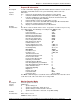
Chapter 1 – AT Commands, S-Registers, and Result Codes S-Registers Certain modem values, or parameters, are stored in memory locations called S-Registers. Use the S command to read or to alter the contents of S-Registers (see previous section). Register Unit S0 1 ring Range 0, 1–255 Default 1 Description Sets the number of rings until the modem answers. ATS0=0 disables auto answer completely. S1 1 ring 0–255 0 Counts the rings that have occurred.
Chapter 1 – AT Commands, S-Registers, and Result Codes S37 decimal 0–19 0 Sets the maximum V.34 “upstream” speed at which the modem attempts to connect. 0 = maximum speed 1 = reserved 2 = 1200/75 bps 3 = 300 bps 4 = reserved 5 = 1200 bps 6 = 2400 bps 7 = 4800 bps 8 = 7200 bps 9 = 9600 bps 10 = 12000 bps 11 = 14400 bps 12 = 16800 bps 13 = 19200 bps 14 = 21600 bps 15 = 24000 bps 16 = 26400 bps 17 = 28800 bps 18 = 31200 bps 19 = 33600 bps S38 decimal 0–23 1 Sets “downstream” data rate where V.
Chapter 1 – AT Commands, S-Registers, and Result Codes S48 decimal 7 or 128 7 Enables (7) or disables (128) LAPM negotiation . The following table lists the S36 and S48 configuration settings for certain types of connections.
Chapter 1 – AT Commands, S-Registers, and Result Codes Result Codes In command mode your modem can send responses called Result Codes to your computer. Result codes are used by communications programs and can also appear on your monitor.
Chapter 1 – AT Commands, S-Registers, and Result Codes 103 104 105 106 107 108 109 110 111 112 113 114 115 116 CONNECT 33333 CONNECT 34666 CONNECT 37333 CONNECT 38666 CONNECT 41333 CONNECT 42666 CONNECT 45333 CONNECT 46666 CONNECT 49333 CONNECT 50666 CONNECT 53333 CONNECT 54666 CONNECT 25333 CONNECT 26666 Connected at 33333 bps Connected at 34666 bps Connected at 37333 bps Connected at 38666 bps Connected at 41333 bps Connected at 42666 bps Connected at 45333 bps Connected at 46666 bps Connected at 49333
Chapter 4 – Voice Commands Chapter 4 – Voice Commands Introduction Important Note: Some Voice commands do not apply to the SMI build. This chapter describes +V command support. The +V Command standard IS-101 Voice Control Interim Standard for Asynchronous DCE (prepared by the TIA Technical Subcommittee TR29.
Chapter 4 – Voice Commands Voice S-Register Summary Voice mode S-Register changes are outlined below. S-Register S0 S7 S10 Description Automatic answer is disallowed in Voice mode. Wait for Carrier After Dial. Default is 60 seconds. In Voice mode, S7 contains the maximum amount of time that the modem will wait during Call Origination, all the time detecting for ring backs, before assuming that the remote station will not go off hook. Automatic disconnect is disallowed in Voice mode.
Chapter 4 – Voice Commands Voice +V Commands Detail +FCLASS=8 Select Voice Mode Description: The +FCLASS=8 command selects voice mode. +VNH Automatic Hang-Up Control Description: Syntax: Values: Enables or disables automatic hang-up. AT+VNH= +VNH=0 Enables automatic hang-ups as in non-Voice modes (such as hanging up the phone when the modem does not detect a data carrier within a given time interval). +VNH=1 Disables automatic hang-ups in non-Voice modes.
Chapter 4 – Voice Commands +VTS Send Voice Tone(s) Description: This command causes the modem to send DTMF digit or hookflash tones with the duration specified by +VTD, to send DTMF digit or hookflash tone duration specified by this command, or to send single or dual tone frequencies with duration specified with this command. AT+VTS= The tone generation string consists of elements in a list where each element is separated by commas. Each element can be: 1.
Chapter 4 – Voice Commands +VTX Start Voice Transmission Process Description: Starts the voice transmission process. The PC sends the data in the format of the previously entered +VSM command, using the flow control method selected by the +FLO command. The voice data is buffered to withstand gaps of missing data from the PC. If the modem does not have any current voice data, the modem sends silence over to the analog destination until the PC provides more voice data.
Chapter 4 – Voice Commands +VIT Set DTE/DCE Inactivity Timer Description: Sets the modem's initial value for the PC/Modem Inactivity Timer. The units are in 1.0 seconds. The PC can disable the Inactivity Timer by using a value of 0 (+VIT=0). The Inactivity Timer serves to ensure that the PC does not leave the modem in a state where it is not accessible by voice-unaware software. The Inactivity Timer is activated when the PC selects the voice fixed-rate.
Chapter 4 – Voice Commands +VLS Select Analog Source/Destination Description: Selects one or more source/destination devices for the analog data to be transmitted. The parameter
Chapter 4 – Voice Commands +VRA Ringback Goes Away Timer Description: Sets the length of time the modem will wait between ringbacks during a call origination before the modem can assume that the remote device has gone off-hook. AT+VRA= A decimal number (0–255) specifying the silence interval time in units of 0.10 seconds between the end of one ring interval and the start of the next ring interval.
Chapter 4 – Voice Commands +VSD Silence Detection Sensitivity Description: Sets the silence detection sensitivity and the required period of silence before the modem reports silence detected at the end of a voice receive, either with the Presumed End of Message (Quiet) or Presumed Hang Up (Silence) event reports. The table below outlines the possible combinations of the +VSD and +VSM commands using the parameter. An parameter value of 0 means that long-term silence detection is disabled.
Chapter 4 – Voice Commands +VSM Select Voice Compression Method Description: Sets the modem to a specified voice compression method, silence compression sensitivity, and voice sampling rate. The modem can maintain a different event detection capability for each compression method. For example, you may want to record your welcome message with the lowest amount of silence removal, with the goal of reducing distortion.
Chapter 4 – Voice Commands +VTD Beep Tone Duration Timer (DTMF/Tone Generation Duration) Description: Sets the default DTMF/tone generation duration used with the +VTS command. This command does not affect the ATD command settings. The parameter range is given by the +VTD=? command, in units of 0.01 seconds. A setting of +VTD=0 specifies a manufacturer-specific time interval. AT+VTD= . A decimal number specifying the default DTMF/tone generation duration in units of 0.01 seconds.
Chapter 4 – Voice Commands DRON=8 DROF=4 DRON=8 RING <.> Reports: Result Codes: +VDR? Displays current or selected values. +VDR=? Displays a list of the supported values. OK if the modem accepts the command ERROR if the parameter is out of range or not in voice mode. +VEM Event Reporting and Masking Description: The +VEM= command can be used to disable an event report, regardless of the modem's state, or of the modem's analog signal source or destination's configuration.
Chapter 4 – Voice Commands Interface Configuration Commands The commands in this section are used to define the interface between the PC and the modem. +VBT Set Modem Flow Control Assert and Deassert Points Description: The +VBT= command is used to set the flow control assert and deassert points inside the modem's internal transmit buffer.
Chapter 4 – Voice Commands +VPP Enable or Disable Voice Mode Packet Protocol Description: The +VPP command enables and disables the Packet protocol for Voice mode operation, and handles the new unsolicited Voice mode result codes. The Packet protocol is used to detect lost octets on the modem-to-PC serial link, and to recover the lost octets by requesting retransmission.
Chapter 4 – Voice Commands Flow Control XON/XOFF flow control is used by the modem to match the PC-to-modem data rate to the line-signaling rate, as well as to the requirements of analog conversion of the voice signals and voice data. In-band, uni-directional XON/XOFF flow control is mandatory. RTS/CTS (V.24 circuits 106 and 133) flow control is optional per the IS-101 standard.
Chapter 4 – Voice Commands Unsolicited Voice Mode Result Codes The form of the unsolicited result codes for voice mode is different from standard modem Command mode result codes. The +V specification refers to these voice mode result codes as "event detection reports". Event detection reports are provided in simple report format when one character is enough to report an event, such as RING.
Chapter 4 – Voice Commands Voice Mode Shielded Codes These codes can be sent in either Command mode or Data mode. The DCE may return the event detection reports after the OK result code from the +FCLASS command. One or more simple event detection reports may be embedded within the data portion of a complex event detection report. Table 3 describes voice mode shielded codes. The number in the first column is the ASCII equivalent (in hex).
Chapter 4 – Voice Commands I L w t r b d K F u p P a f V v i E Y m % & ' ( ) all other (6C) Event Number 13 (Loop Current Interruption). Usually indicates a remote hang up. (4C) Event Number 14 (Loop Current Polarity Reversal). May indicate a hang up or a receive, depending on CO implementation. (77) Event Number 15 (Call Waiting/Beep Interrupt). (74) Event Number 17 (TDD Detected - 1400/1800). (72) Event Number 18 (Ring Back). (62) Event Number 19 (BUSY). May be repeatedly sent.
Chapter 4 – Voice Commands DTE/DCE Interface Rates The table below indicates the anticipated modem-to-computer interface rates for both the 7.2 bits-persample rate and the 8 bits-per-sample rate. Projected DTE/DCE Interface Rates for 7.2/8K Hz Sample Rates Bits per Projected DTE/DCE Projected DTE/DCE Sample I/F Rate @ 7.2K Hz I/F Rate @ 8K Hz 0.
Chapter 5 – Country/Regional Code Configuration Chapter 5 – Country/Regional Code Configuration Different countries/regions have different requirements for how modems must function. Therefore, before you use the modem, you must configure it to match the defaults of the country/region in which you are using it. To configure the modem for a specific country/region, execute the following AT commands: 1. Type AT%T19,0,nn (nn stands for the country/region code). Press Enter. OK is displayed. 2.
Index Index # + #CBA – Callback Attempts ....................................... 36 #CBD – Callback Delay ............................................ 36 #CBF – Callback Failed Attempts Display ................ 36 #CBFR – Callback Failed Attempts Reset ............... 36 #CBI – Local Callback Inactivity ............................... 36 #CBN – Store Callback Password............................ 36 #CBP – Callback Parity ............................................ 37 #CBR – Callback Security Reset......
Index A A – Answer ................................................................. 7 \A – Select Maximum MNP Block Size..................... 17 A/ – Repeat Last Command ....................................... 7 Abort timer – S7 ....................................................... 38 Adaptive Answer Result Code – %A ........................ 20 Answer – A ................................................................. 7 Asynchronous Communications Mode – &Q ............
Index MNP Error Correction............................................... 19 Model Identification Request – +GMM ..................... 28 Modulation Handshake – N ...................................... 11 Modulation Reporting Control – +MR ....................... 30 Modulation Selection – +MS .................................... 30 Monitor Speaker Mode – M ...................................... 10 N \N – Error Correction Mode ...................................... 19 N – Modulation Handshake ..............
Index Voice Gain for Received Voice Samples – +VGR .... 47 Voice Mode Result Codes ........................................ 57 Voice Mode Shielded Codes .................................... 59 W W – Result Code Options ......................................... 12 Wait time for dial tone – S6 ...................................... 38 X X – Select Result Code & Call Monitor Progress ..... 13 X – XON/XOFF Pass-Through ................................. 20 XON/XOFF Pacing Control – &E..........................