LAN-to-LAN Routing for Central-Site and Branch Office Networks Model MTASR2-201 Quick Start Guide
Quick Start Guide 82087301 Revision B DSU RouteFinder (Model No MTASR2-201) This publication may not be reproduced, in whole or in part, without prior expressed written permission from Multi-Tech Systems, Inc. All rights reserved. Copyright © 1998, 1999, by Multi-Tech Systems, Inc. Multi-Tech Systems, Inc. makes no representations or warranties with respect to the contents hereof and specifically disclaims any implied warranties of merchantability or fitness for any particular purpose.
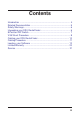
Contents Introduction ................................................................................... 4 Related Documentation ................................................................. 5 Safety Warnings ............................................................................ 6 Unpacking your DSU RouteFinder ................................................ 6 8-Position DIP Switch .................................................................... 7 V.35 Shunt Procedure .......................
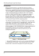
DSU RouteFinder Quick Start Guide Introduction Welcome to Multi-Tech's new DSU RouteFinder, Model MTASR2-201, which provides secure and seamless LAN-toLAN routing capability and can also provide dial-up capability. This unit supports multiple WAN services and supports a wide range of routing protocols including IP, IPX, TCP, and RIP version 2.
Introduction Related Documentation This DSU RouteFinder Quick Start Guide is intended to be used by qualified systems administrators and network managers. This quick start guide provides the necessary information for a qualified person to unpack, cable, load software, and configure the unit for proper operation. A detailed DSU RouteFinder User Guide is also provided with your unit. The user guide provides in-depth information on the features and functionality of Multi-Tech’s DSU RouteFinder.
DSU RouteFinder Quick Start Guide Safety Warnings 1. Never install telephone wiring during a lightning storm. 2. Never install telephone jacks in wet locations unless the jack is specifically designed for wet locations. 3. Never touch uninsulated telephone wires or terminals unless the telephone line has been disconnected at the network interface. 4. Use caution when installing or modifying telephone lines. 5. Avoid using a telephone (other than a cordless type) during an electrical storm.
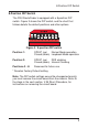
8-Position DIP Switch 8-Position DIP Switch The DSU RouteFinder is equipped with a 8-position DIP switch. Figure 3 shows the DIP switch, and the chart that follows details the default positions and other options. 1 2 3 4 5 6 7 8 Figure 3. 8-position DIP switch Position 1: OPEN* (up) Normal Mode operation Closed (down) Loopback Mode operation Position 2: OPEN* (up) DDS clocking Closed (down) Internal Clocking Positions 3 - 8: Reserved for future use.
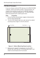
DSU RouteFinder Quick Start Guide V.35 Shunt Procedure If you are using an external DCE device on the WAN 2 RS232/ V.35 port, and the connection will be a V.35 connection, the internal shunt must be moved from the RS232C (default) position prior to cabling and power-up. The following steps detail the procedures for switching the shunt. Step Procedure 1 Ensure that the external power supply is disconnected from the DSU RouteFinder.
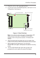
V.35 Shunt Procedure 4 Place the unit on a flat, grounded surface. 5 Pry the shunt out of the RS232 position, and insert it in the V.35 position. See Figure 5. 8-Position DIP Switch LEDs 5 6 7 8 RAM Sockets Back Panel Connectors V.35 Shunt Position RS232C Shunt Position Figure 5. Shunt Positions Note: if you wish to make changes to the 8-position DIP switch, do so at this time. For details on DIP switch settings, refer to the previous section, “8-Position DIP Switch”.
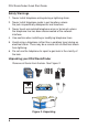
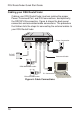
DSU RouteFinder Quick Start Guide Cabling your DSU RouteFinder Cabling your DSU RouteFinder involves making the proper Power, Command Port, and DSU connections, and optionally, the RS232/V.35 connection. Figure 6 shows the back panel connectors and associated cable connections. The procedure that follows lists the steps for connecting the external cables to your DSU RouteFinder. RS232/V.
Cabling Cabling Procedure Step Procedure 1. Connect one end of the power supply to a live AC outlet and connect the other end to the DSU RouteFinder as shown in Figure 6. The power connector is a 6-pin circular DIN connector. 2. Connect the DSU RouteFinder to a PC using the RJ-45 to DB-9 (female) cable provided with your unit. Plug the RJ45 end of the cable into the Command port of the DSU RouteFinder and the other end into the PC’s COM port. See Figure 6. 3.
DSU RouteFinder Quick Start Guide Loading your Software The following loading procedure does not provide every screen or option in the process of installing the RouteFinder software. It is assumed that a technical person with a thorough knowledge of Windows and the software loading process is doing the installation. 1. Run Windows on the PC that is connected to the DSU RouteFinder’s Command Port. 2. Insert the RouteFinder Disk 1 into the disk drive on the PC that is connected to the DSU RouteFinder. 3.
Software 4. When the Welcome screen appears, press Enter or click Next> to continue. 5. Press Enter or click Next> to continue. 6. When the Select Program Folder dialog box appears, click (to the right of the text) on the Program Folders text box, then backspace through “| RASFinder” until the cursor is next to the letter “r” in “RouteFinder”; this will become the name of the icon group. Press Enter or click Next> to continue.
DSU RouteFinder Quick Start Guide 7. The next dialog box enables you to designate the COM port of the PC that is connected to the DSU RouteFinder. On the Select Port field, click on the down arrow and choose the COM port of your PC (COM1 -- COM4) that is connected to the DSU RouteFinder. 8. Click OK to continue. 9. Click Finish to continue. The “Do you want to perform upgrade?” dialog box is displayed.
Software 10. Click No to skip the upgrade process. The “Do you want to download default setup?” dialog box appears. 11. Click Yes to download the default setup. (Clicking on No prevents you from setting up the defaults and downloading them to the DSU RouteFinder; instead, you are returned to the program manager, where in Windows 95 you will see a window with shortcut icons for all the various utility programs in the software.) 12. The Novell IPX Protocol Default Setup dialog box appears.
DSU RouteFinder Quick Start Guide 14. Router Name: If this is the only DSU RouteFinder on your network, you can use the default Router Name (MTROUTER); otherwise, you must assign a new Router Name in this field. The Router Name can be any printable ASCII string of up to 47 characters. The DSU RouteFinder uses this name to advertise its service in the IPX internetwork. 15.
Software 16. WAN1 and WAN 2: Click the associated check box if one or the other is to be disabled; otherwise, leave the Enable checked and double-click the Network number text box and enter the WAN Network number. The WAN network numbers have to be assigned by the network administrator and must be unique throughout the entire internetwork. Note: The WAN ports do not have the capability of learning the network number, unlike the LAN port (i.e., the WAN ports do not have a file server). 17.
DSU RouteFinder Quick Start Guide 1 is selected on the 8-position DIP switch on the circuit board (External or DDS Clocking is the default). If WAN 1 is not on a Direct Connection or Leased Line, click that option to disable it, then enter your ISP’s phone number in the Dial Number field. 23. Set up all parameters in the WAN 2 group.
Software The Writing Setup dialog box (with the current date and the file size in bytes) is displayed as the software sends the configuration file to the DSU RouteFinder. The Rebooting dialog box is displayed. 26. Check to ensure that the Fail LED on the DSU RouteFinder goes Off after the download is complete and the DSU RouteFinder is rebooted (the Rebooting dialog box goes away). 27. Win3.
DSU RouteFinder Quick Start Guide Limited Warranty Multi-Tech Systems, Inc. (“MTS”) warrants that its products will be free from defects in material or workmanship for a period of two years from the date of purchase, or if proof of purchase is not provided, two years from date of shipment. MTS MAKES NO OTHER WARRANTY, EXPRESSED OR IMPLIED, AND ALL IMPLIED WARRANTIES OF MERCHANTABILITY AND FITNESS FOR A PARTICULAR PURPOSE ARE HEREBY DISCLAIMED.
Warranty, Service and Regulatory Information Service Multi-Tech has an excellent staff of technical support personnel available to help you get the most out of your Multi-Tech product. Refer to your DSU RouteFinder User Guide for Warranty and Service information. FCC Declaration NOTE: This equipment has been tested and found to comply with the limits for a Class A digital device, pursuant to Part 15 of the FCC Rules.
82087301