
User guide

V.35 Shunt Procedure
9
4 Place the unit on a flat, grounded surface.
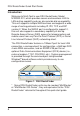
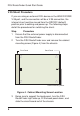
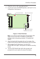
5 Pry the shunt out of the RS232 position, and insert it in the
V.35 position. See Figure 5.
5
6
7
8
V.35 Shunt Position
RS232C Shunt Position
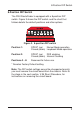
Back Panel Connectors
8-Position DIP Switch
RAM Sockets
LEDs
Figure 5. Shunt Positions
Note: if you wish to make changes to the 8-position DIP
switch, do so at this time. For details on DIP switch
settings, refer to the previous section, “8-Position DIP
Switch”.
6 Align the board with the guide slots on the inside of the
chassis and carefully slide the board back into the chassis.
7 While supporting the back panel, turn the DSU
RouteFinder over again, and replace the cabinet mounting
screw.
8 Turn the DSU RouteFinder right side up again and
proceed to the next section to connect the cables.