AcquiSuite USB Modem Addendum Applies to: A8812 AcquiSuite, A8810 AcquiSuite EMB, A7810 AcquiLite Date Nov 30, 2011 Page 1 USB Modem Addendum
Copyright Information Copyright © 2001 - 2011 by Obvius Obvius and AcquiSuite are trademarks of Obvius Holdings LLc Other brand and product names are trademarks or registered trademarks of their respective holders. U.S. Government Restricted Rights: Use, duplication or disclosure by the Government is subject to restrictions set fourth in subparagraph (a) through (d) of the Commercial Computer Restricted Rights clause at FAR 52.
Table of Contents Introduction................................................................................................................................................................................................... 4 Features......................................................................................................................................................................................................... 4 Planning the Installation of a “POTS” Modem.............................
Introduction Beginning with AcquiSuite firmware version v02.11.1106b, the AcquiSuite Data Acquisition Servers (DAS) support the following optional USB modems: • USRobotics USR5637 -- V.92 “POTS”* modem • Radicom-V92HU-E2 -- V.92 “POTS” modem • TrendNet TFM-561U – V.92 “POTS” modem (a clone of the Radicom V92HU-E2) • MultiTech MTCBA-G-U-F4 – GPRS/GSM cellular modem * “POTS” = Plain Ol' Telephone System, aka Landline Features • No modem drivers required. • USB hot-plugging fully supported.
Planning the Installation of a “POTS” Modem To install a USB “POTS” modem, you will typically need the following: 1. [__] The modem itself; 2. [__] The modem's documentation and drivers CD, in case you need to install the modem on a PC to verify proper operation; 3. [__] RJ11 telephone cord of sufficient length; 4. [__] USB extension cable if the modem cannot be plugged directly into the AcquiSuite/AcquiLite DAS's USB port.
Planning the Installation of the Multitech GPRS/GSM Cellular Modem To install the Multitech GPRS/GSM cellular modem, you will typically need the following: 1. [__] The modem itself; 2. [__] The modem's documentation and drivers CD, in case you need to install the modem on your PC to verify proper operation; 3. [__] USB cable to connect the modem to the AcquiSuite/AcquiLite DAS's USB port.
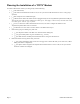
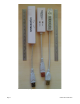
Comparing “POTS” Modems The 3 new POTS modems are pictured on the next page, with close-ups on the following pages. Compared to the built-in modems of the AcquiSuite A8812, these USB modems each lack speakers and each have a different set of status LEDs (or in the case of the Radicom have no speaker and NO LEDs.) To compensate for this lack, the AcquiSuite and AcquiLite DAS displays status messages on its 2x16 LCD display during all phases of: • Hot-plugging, • Dial-in, • Dial-out, • Data uploading.
Illustration 1: Comparing "POTS" modems: USRobotics, TrendNET, Radicom Page 8 USB Modem Addendum
The USRobotics USR5637 • Power LED – on when modem is receiving power from the USB port. • Data LED – blinks when modem is connected and transferring data to the remote modem.
The Radicom-V92HU-E2 • No LEDs whatsoever. • No speaker.
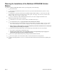
The TrendNET TFM-561U • A “clone” of the Radicom-V92HU-E2, but with LEDs. • Link LED – on when the modem has “connected” to the remote modem. • Data LED – blinks when data sent/received to the remote modem. • No speaker.
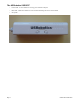
Cellular Modems In addition to the onboard cellular-modem options of the A8812 model, the AcquiSuite/AcquiLite DAS support the following USB cellular modems: • MultiTech MTCBA-G-U-F4 – GPRS/GSM cellular modem MultiTech MTCBA-G-U-F4 – USB GRPS cellular modem This modem is pictured below, showing the mounting bracket provided by Multitech: Page 12 USB Modem Addendum
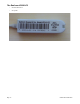
Here is a close-up of the Mulitech's front-panel showing the LEDs and slot for GSM SIM card: Page 13 USB Modem Addendum
New Features of the AcquiSuite/AcquiLite's LCD Together with support for USB modems, the LCD console of the AcquiSuite/AcquiLite DAS has several new features to aid in debugging and diagnostics of dial-up connections if a PC and web-browser is not available. The new LCD behavior is intended to be very intuitive and simple, but for the sake of completeness it is described here.
Installation Step 1: Plug it in To begin “installing” a USB modem, plug it into the AcquiSuite or AcquiLite DAS's USB port. No modem drivers are needed, and the AcquiSuite/AcquiLite DAS fully supports hot-plugging of USB devices. When the AcquiSuite/AcquiLite DAS detects the modem, it should display a message on its LCD, similar to this: The actual message may vary a bit because the description (“USB Modem”) is loaded from the USB modem itself.
Note: If dial-in or dial-out is enabled but the DAS does not find a modem of the expected type or the modem fails to initialize, the DAS will report this inconsistency as an error on its LCD and in its web administration pages, and continue trying to detect and initialize the modem. If this error condition persists for an entire day (24 hours), the DAS will gracefully reboot itself in a “last-ditch” attempt to fix any possible communication problem with the modem.
2. Page 17 You are using a USB hub, and possibly other USB devices, and the combination of the hub, other devices and the USB modem exceeds the total power the DAS is able to provide to its USB port.
Step 3: Enable & Configure Dial-Out If you wish the DAS to automatically dial-out to upload meter data, you must enable and configure this via the DAS's “Dialout Setup” web page: Note that the time-of-day that the DAS dials out is configured in the “Log File Data >> Upload/Setup” page. This is described in the Installation Manual for the DAS. The Dial-Out Watchdog If dial-out is enabled, the DAS will also enable a “dial-out watchdog timer”.
Test Dial-Out by Running a “Connection Test” Once you've enabled and configured dial-out, test these settings by running a Connection Test, via the DAS's “Testing / Diags >> Connection Test” web page.
LCD Messages While Dialing-Out The AcquiSuite/AcquiLite DAS will display the following messages on its LCD while dialing out. These can be used to diagnose problems if a PC or other full-featured web browser is not available. Preparing to Dial Out The DAS is performing housekeeping tasks like compressing log-files. This can take ~30 seconds or more if the DAS's flash-memory is full. Dialing Out The DAS is about to dial out. Calling The DAS displays the number it is dialing.
Modem Connecting / Waited N so far If the call takes longer than 15 seconds to connect, the DAS will remind you that it is still connecting with this message, including the total number of seconds it has waited so far. This message will update every 3 seconds. The DAS waits a total of 90 seconds to connect, then gives up.
Connect failed: NO LINE or NO CARRIER The DAS now begins the process of uploading data for each of the enabled upload channels. Example messages are shown below: Uploading Ch N: / Sending Status The DAS is sending its status (system health, etc.) to the server configured for upload channel #1: Uploading Ch N: / Sent XX% Data Next the DAS sends any queued meter data for channel #1, and periodically reports the % of data it has sent so far.
The DAS will then continue on with channels 2 through 4 (if they are enabled): Page 23 USB Modem Addendum
Dialout Success: / Hanging up, Done If the entire upload cycle completes, the DAS will display the following on its LCD. If the call was dropped for some reason, the DAS will display the particular modem or PPP error.
Step 4: Enable & Configure Dial-In “Dial-in” allows the DAS to be remotely administered and allows data to be “pulled” from the DAS using Obvius' EnerTraxDL software. “Dial-in” is not supported with cellular modems. It is supported with all “POTS” modems, including all USB “POTS” modems. To enable dial-in, check the “Dialin Enabled” box in the DAS's “Dialin Setup” web page and click Apply.
The Dial-In Watchdog If dial-in is enabled, the DAS will also enable a “dial-in watchdog timer”. The “dial-in watchdog timer” will cause the DAS to gracefully reboot itself if it fails to successfully initialize the modem to receive incoming calls at least once every 24 hours. To be clear: The DAS does not need to actually receive a call every 24 hours, it simply needs to communicate with the modem and successfully prepare to receive dial-in calls once every 24 hours.
Modem Connected / Receiving PPP The DAS has answered the call, connected to the remote modem, and is negotiating a PPP connection Dial-in Failed: Bad PPP User/Password If the remote system fails to provide the proper username or password, the DAS will report the following on its LCD: Dial-in OK: Remote hung up!? The dial-in call ended with the remote end hanging up. This is not an error unless unexpected. Within 10 to 20 seconds, the DAS will report it is ready to receive another call.
Page 28 USB Modem Addendum
Detailed Explanation of the “Modem Setup” Options The “Modem Setup” Web Page This configuration option will allow you to configure specific features in the modem if needed. For most applications, the default settings are ok. The options are as follows: Scan for New Modem button: When clicked, the AcquiSuite will begin searching for the best modem to use. It first scans any USB devices and then looks for an onboard modem (on a daughtercard, A8812 only). While the scan is in progress, a message is displayed.
The “Modem Setup” Page -- Options for GSM Cellular Modems GSM band: Lets you select the GSM frequency band. GSM signal strength: Displays the most recent signal strength reported by the modem. GSM signal quality: Displays the most recent signal quality reported by the modem. The “Modem Setup” Page -- Modem Diagnostics This page displays detailed information about the modem such as its model code, firmware version (for some modems) and supported features.