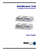
MultiModem® iCell Intelligent Wireless Modem User Guide
MultiModem® iCell User Guide Intelligent Wireless Modem MTCMR-E1, -C1, -G2, -H4, -EV2, optional -GP builds S000484D, Revision D Copyright This publication may not be reproduced, in whole or in part, without prior expressed written permission from Multi-Tech Systems, Inc. All rights reserved. Copyright © 2010 by Multi-Tech Systems, Inc. Multi-Tech Systems, Inc.
Contents Chapter 1 – Product Description and Specifications ............................................................................................... 4 Product Description .................................................................................................................................................. 4 Related Documentation ............................................................................................................................................ 5 Universal IP .......
Chapter 1 – Product Description and Specifications Product Description The Multi-Tech MultiModem® iCell is a mid-range wireless modem containing an embedded TCP/IP protocol stack for Internet connectivity, serial and USB connectors for modem configuration, and a General Purpose Input/Output (GPIO) connector for customer interface connection. All MultiModem iCells can be desktop or panel mounted.
Chapter 1 Related Documentation Universal IP All MultiModem iCell modems are equipped with an embedded TCP/IP protocol stack to automate the connection process and open a socket for bidirectional data transmission. Multi-Tech’s Universal IP supports Telnet, SMTP/POP, FTP, TCP, UDP, PPP as well as other automatic call management options. AT Commands: The embedded TCP/IP stack on the MultiModem iCell modems is configured using the Universal IP (UIP) AT Commands.
Chapter 1 Safety General Safety The modem is designed for and intended to be used in fixed and mobile applications. “Fixed” means that the device is physically secured at one location and is not able to be easily moved to another location. “Mobile” means that the device is designed to be used in other than fixed locations. Caution: Maintain a separation distance of at least 20 cm (8 inches) between the transmitter’s antenna and the body of the user or nearby persons.
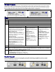
Chapter 1 Front Panel The front panel is designed with two groups of LEDs that display modem activity and signal strength. The first group of LEDs display modem activity, such as transmit and receive data, carrier detection, link status, terminal ready indicating connection to the pc, and the power indicator. The three Signal LEDs display the signal strength level of the wireless connection. The SIM door on the right side of the modem provides access to the SIM card holder for those configurations.
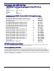
Specifications Features Performance Band, Frequency Packet Data Circuit-Switched Data Short Message Services-SMS Antenna Connector SIM Connector External Connectors Voltage Physical Description Operating Temperature * Storage Temp Humidity Certifications * MTCMR-E1 EDGE: E-GPRS Class 12, GPRS: Class 10 Quad-band GSM/GPRS/EDGE 850/900/1800/1900 MHz MTCMR-C1 CDMA2000 1xRTT MTCMR-G2 GPRS Class 10 Dual-band 800/1900 MHz CDMA; 800 MHz and 800/1900 MHz with R-UIM support Up to 153.
Chapter 1 Power MTCMR-E1 Sleep .091A, .84W @ 9V, .048A, .96W @ 20V, .034A, 1.088W @ 32V Typical .149A, 1.37W @ 9V, .077A, 1.54W @ 20V, .054A, 1.73W @ 32V Max .416A, 3.77W @ 9V, .190A, 3.80W @ 20V, .124A, 3.97W @ 32V Peak. 2.5A @ 9V, 0.895A @ 20V, 0.625A @ 32V MTCMR-C1 Sleep .048A, .44W @ 9V, .027A, .54W @ 20V, .021A, .67W @ 32V Typical .128A, 1.18W @ 9V, .065A, 1.30W @ 20V, .046A, 1.47W @ 32V Max .360A, 3.31W @ 9V, .171A, 3.42W @ 20V, .115A, 3.68W @ 32V MTCMR-G2 MTCMR-H4 Sleep .069A, .64W @ 9V, .
Antenna Specifications GSM/EGSM Antenna Requirements/Specifications Frequency Range: Impedance: VSWR: Typical Radiated Gain: Radiation: Polarization: Wave: 824 – 960 MHz / 1710 – 1990 MHz 50 Ohms <2.0:1 3 dBi on azimuth plane Omni Vertical Half Wave Dipole Antennas Available from Multi-Tech Systems, Inc.
Chapter 1 Global Positioning System (GPS) Technical Specifications Receiver Type Accuracy Open Sky TTFF Sensitivity Tracking Update Rate Dynamics Operational Limits Datum Interface Protocol L1 Frequency, GPS C/A code, SBAS Capable, 51 Channel Acquisitions, 14 Channel Tracking Position 2.5m CEP, Velocity 0.1m/sec Hot start 1 second, Cold start 29 seconds average, Reacquisition <1s -161dBm 1 Hz standard 4G Altitude <18,000m or Velocity < 515m/s Default WGS-84 UART NMEA-0183 V3.
Chapter 1 GPIO (General Purpose Input/Output) Connector The GPIO pins are configured using Universal IP (UIP) AT Commands. Refer to the Universal IP (UIP) AT Command Reference Guide on your MultiModem CD. The following table explains the GPIO functions: Pin Number Pin 1 Pin 2 Pin 3 Pin 4 Pin 5 Description DIO 0 DIO 1 DIO 2 / ADC 0 DIO 3 / ADC 1 ADC 2 Pin 6 Gnd GPIO 6-PinConnector The GPIO pins can be configured independent of each other. ● Pin 1 Digital Input, 24 Volt tolerant.
Chapter 2 – Activation and Installation Activate Your Wireless Account Please refer to the wireless account Activation Notices included with your unit and located on the MultiModem CD. Choose the one for your wireless network provider and follow the directions to activate your account. Phone Numbers for the Wireless Modem Every wireless modem will have its own unique phone number. The phone number may simply be given to you by your wireless service provider or it may be on the SIM card or both.
Chapter 2 Connect the Antenna, Serial Cable, GPIO Cable, and Power 1. Connect a suitable antenna to the SMA connector (see antenna specifications in Chapter 1). 2. If you are connecting to a serial interface, connect the DE9 connector (9-pin) of the RS232 cable to the RS232 connector on the modem and connect the other end to serial port on your PC. If you are connecting to an USB interface, connect an USB cable to the USB connector on the back of the unit and the other end to the USB port on your PC.
Chapter 2 Optional – Attach the Modem to a Flat Surface Before you mount your modem to a permanent surface, verify signal strength, refer to Using Your Wireless Modem, Verify Signal Strength in Chapter 3. Note: No matter what orientation is used for mounting your MultiModem, the antenna should always be vertical and pointing upwards as the floor or ground may impede the performance of the antenna. The modem can be panel mounted with screws spaced according to the measurement shown.
Chapter 2 USB Virtual COM Port Installation Windows XP, VISTA, 2003 Server, 2008 Server, Windows 7 (32-bit or 64-bit), Linux (Kernel 2.6.xx using CDC-ACM module) are supported. For Linux, a 2.6 kernel is required. The standard CDC-ACM driver will work. For Windows XP, VISTA, 2003 Server, 2008 Server, and Windows 7, run the automatic installer from your product CD or run install.bat from the UIP_VCOM_autoinstall directory on your product CD and proceed with the procedure below.
Chapter 2 8. There will be a transitory screen, then the process will complete. Click on the Finish button. 9. Next, continue with installing the modem driver. Install the Modem Driver 1. 2. Click on the Control Panel button from the main splash screen on the CD. The Control Panel is displayed; double-click on Phone and Modem Options icon. Then click on the Modems tab. Multi-Tech Systems, Inc.
Chapter 2 3. When this Phone and Modem Options screen appears, click on the Add button. 4. On the Install New Modem screen, click Don’t detect my modem, I will select it from a list. Then click Next >. 5. On the Install New Modem screen, click the Have Disk button to browse for the driver file on the MultiModem CD. Then click Next>. Multi-Tech Systems, Inc.
Chapter 2 6. Make sure that the MultiModem CD is inserted into your CD-ROM, browse to your MultiModem CD. 7. Select the MTSMCIP_MTCMRIP.INF file. Then click OK. 8. In the Models window, scroll down the list of Models and select the model that is applicable to your modem. Once you have selected your model, click on Next>. Multi-Tech Systems, Inc.
Chapter 2 9. You will now have to choose which com port the MultiModem is connected to. If you know exactly which port your modem is on, click on that port; otherwise, check your Control Panel – Device Manager to see what COM port(s) is available. Click Next >. 10. To finish the install, click on Finish. You have now successfully installed the MultiModem driver to your PC. Verifying That Your Modem Has Been Installed Successfully 1.
Chapter 3 – Using Your Wireless Modem Phone Numbers for the Wireless Modem ● Every wireless modem will have its own unique phone number. ● The phone number may simply be given to you by your wireless service provider or it may be on the SIM card or both. Wireless provider implementations may vary. Examples of Useful AT Commands A Note About HyperTerminal In order to verify signal strength and roaming status, you must use a terminal application such as HyperTerminal.
Chapter 3 Connecting to the Internet Internet access can be setup in Windows Dial-Up Networking (DUN) of the computer that the MultiModem iCell is serving. For a GPRS network, you have to create an Access Point Name in the Phone and Modem Options dialog in Windows Control Panel and then create your Windows Dial-Up Connection (DUN). Connecting to a CDMA Network for Internet Access Once you have activated your wireless account, you can establish your Internet connection through a Windows dial-up session.
Chapter 3 Create Your Dial-Up Connection in Windows Vista and XP 1. 2. 3. 4. 5. 6. 7. 8. 9. 10. 11. 12. 13. 14. 15. 16. Click on Start and then click on Control Panel. In the Control Panel, double-click on Network Connections. On the Network Connections screen on the left-hand side under Network Tasks, click on Create a new connection. The New Connection Wizard should appear. It will walk you through setting up your Internet connection. Click on Next > to begin.
Chapter 3 Generic Dial-Up Method - Non-Windows 1. To disable the IP stack, enter AT+WOPEN=0 2. To set up an Access Point Name (APN): AT+CGDCONT=1, “IP”,”” 3. Where is the APN server supplied by your carrier If GPRS/EDGE/HSPA, dial onto the network using ATD*99***1# If CDMA, EV-DO, dial onto the network using ATD#777 Serial Baud Rate Your MultiModem iCell is defaulted to a serial baud rate of 115200 from the factory.
Appendix A – Regulatory Compliance EMC, Safety, and R&TTE Directive Compliance The CE mark is affixed to this product to confirm compliance with the following European Community Directives: Council Directive 2004/108/EC of 31 December 2004 on the approximation of the laws of Member States relating to electromagnetic compatibility; and Council Directive 2006/95/EC of 12 December 2006 on the harmonization of the laws of Member States relating to electrical equipment designed for use within certain voltage lim
Appendix B – DC Power Cable DC Power Cable Dimensions Multi-Tech Systems, Inc.
Appendix C – Environmental Information Waste Electrical and Electronic Equipment (WEEE) Statement July, 2005 The WEEE directive places an obligation on EU-based manufacturers, distributors, retailers and importers to take-back electronics products at the end of their useful life. A sister Directive, ROHS (Restriction of Hazardous Substances) complements the WEEE Directive by banning the presence of specific hazardous substances in the products at the design phase.
Environmental Information Restriction of the Use of Hazardous Substances (RoHS) Multi-Tech Systems, Inc. Certificate of Compliance 2002/95/EC Multi-Tech Systems, Inc. confirms that this product now complies with the chemical concentration limitations set forth in the directive 2002/95/EC of the European Parliament (Restriction Of the use of certain Hazardous Substances in electrical and electronic equipment - RoHS) These Multi-Tech Systems, Inc.
Environmental Information C – RoHS 依照中国标准的有毒有害物质信息 根据中华人民共和国信息产业部 (MII) 制定的电子信息产品 (EIP) 标准-中华人民共和国《电子信息产品污染控制管理办法》(第 39 号),也称作中国 RoHS,下表列出了 Multi-Tech Systems Inc.
INDEX C Canadian Regulations ................................................................. 25 CDMA technology......................................................................... 5 CE Mark ...................................................................................... 25 Circuit Switched Data ................................................................... 8 C-RoHS........................................................................................ 29 D DC Power Cable .................