MultiModem® iCell MTCMR User Guide
MULTIMODEM® ICELL USER GUIDE MultiModem® iCell User Guide Models: MTCMR-E1, -C1, -C2 -G2, -H5, -EV2, -EV3, optional -GP builds Part Number: S000484, Version 9.3 Copyright This publication may not be reproduced, in whole or in part, without the specific and express prior written permission signed by an executive officer of Multi-Tech Systems, Inc. All rights reserved. Copyright © 2013 by Multi-Tech Systems, Inc. Multi-Tech Systems, Inc.
CONTENTS Contents Product Overview .................................................................................................................................................... 6 Overview ....................................................................................................................................................................... 6 Model Options ....................................................................................................................................
CONTENTS MTCMR-C2 ................................................................................................................................................................ 29 MTCMR-C2-GP .......................................................................................................................................................... 30 MTCMR-E1 ......................................................................................................................................................
CONTENTS Setting the Access Point Number (APN) in Modem's Properties ............................................................................ 45 Creating a Dial-up Connection in Linux..................................................................................................................... 45 Setting the Serial Baud Rate ....................................................................................................................................... 45 Recovery ..........................
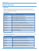
PRODUCT OVERVIEW Product Overview Overview MultiModem iCell modems provide wireless data communications and integrate seamlessly with other applications. MultiModem iCell includes Universal IP® stack, which allows users to implement functions such as persistent connectivity and event monitoring.
PRODUCT OVERVIEW Package Contents Note: For HSPA+, EDGE, and GPRS devices, your wireless provider supplies the SIM card. Other models do not use SIM cards. Unbundled Package with No Accessories 1 modem Note: Package does not include mounting screws, AC or DC power supply, and antenna(s).
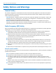
SAFETY NOTICES AND WARNINGS Safety Notices and Warnings General Safety The modem is designed for and intended to be used in fixed and mobile applications. Fixed means the device is physically secured at one location and cannot be easily moved to another location. Mobile means the device is used in other than fixed locations. CAUTION: Maintain a separation distance of at least 20 cm (8 inches) between the transmitter’s antenna and the body of the user or nearby persons.
SAFETY NOTICES AND WARNINGS ■ Lors de l'installation de l'équipement dans un bâti, veillez à ce que la charge mécanique soit homogène de sorte à éviter toute situation potentiellement dangereuse. Le bâti doit supporter le poids de l'ensemble des équipements qu'il contient. ■ Assurez-vous que le circuit d'alimentation principale est capable de gérer la charge de l'équipement. Consultez l'étiquette d'alimentation sur l'équipement pour connaître les spécifications relatives aux charges.
SAFETY NOTICES AND WARNINGS ■ UL evaluated this device for use in ordinary locations only. UL did NOT evaluate this device for installation in a vehicle or other outdoor locations. UL Certification does not apply or extend to use vehicles or outdoor applications or in ambient temperatures above 40° C. User Responsibility Respect all local regulations for operating your wireless device. Use the security features to block unauthorized use and theft.
LEDS, CONNECTORS, AND SPECIFICATIONS LEDs, Connectors, and Specifications Front MTCMR-E1, -G2, -H5 MTCMR-C1, -C2, -EV2, -EV3 LEDs LED Description TD Transmit Data: Lights when device transmits data. Not valid while in USB mode. RD Receive Data: Lights when device receives data. Not valid while in USB mode. CD Carrier Detect: Lights when there is a data connection. Not valid while in USB mode. LS Link Status: LED behavior depends on model.
LEDS, CONNECTORS, AND SPECIFICATIONS LED Description OFF indicates device is turned off or not powered. OFF indicates device is turned off or in download mode. Flashing at 75 ms on/ 75 ms off/75 ms on/3 sec off indicates one or more GPRS contexts activated. Flashing at 500 ms on/ 25 ms off indicates packet switched data transfer in progress. OFF indicates ME is in one of the following modes: power down mode, airplane mode, non-cyclic sleep mode with no temporary wake-up event in progress.
LEDS, CONNECTORS, AND SPECIFICATIONS MTCMR-H5 Specifications Category Description General Performance HSPA+ Frequency Bands Penta band 850/900/1700/1900/2100 MHz Speed Packet Data HSDPA data service of up to 21.0 Mbps HSUPA data service of up to 5.76 Mbps Physical Description Weight 0.45 lbs. (200 g) Dimensions 3.1 in x 4.9 in x 1.1 in (7.9 cm x 12.4 cm x 2.8 cm) Connectors Cellular 50 ohm SMA (female connector) RS-232 DE9 GPIO 6 pin 2x3 style Power 2.
LEDS, CONNECTORS, AND SPECIFICATIONS Category Description Radio Compliance FCC Part 22 FCC Part 24 RSS 132 RSS 133 EN 301 511 EN 301 489-1 EN 301 489-3 (GPS models only) EN 301 489-7 EN 301 489-24 EN 301 908 AS/ACIF S042.1, S042.3 Safety Compliance UL/cUL 60950-1 2nd Ed IEC60950-1 2nd Ed am.1 Network Compliance PTCRB AT&T 1 UL Listed at 40° C, limited by power supply.
LEDS, CONNECTORS, AND SPECIFICATIONS Category Description Power 2.
LEDS, CONNECTORS, AND SPECIFICATIONS Category Description Dimensions 3.1 in x 4.9 in x 1.1 in (7.9 cm x 12.4 cm x 2.8 cm) Connectors Cellular 50 ohm SMA (female connector) RS-232 DE9 GPIO 6 pin 2x3 style Power 2.
LEDS, CONNECTORS, AND SPECIFICATIONS MTCMR-G2 Specifications Category Description General Performance GPRS: Class 10 Frequency Bands Quad-band GSM/GPRS/EDGE: 850/900/1800/1900 MHz Speed Packet Data Up to 85.6K bps, coding schemes CS1 to CS4 Circuit Switched Data Up to 14.4 Kbps transparent and non-transparent Physical Description Weight 0.45 lbs. (200 g) Dimensions 3.1 in x 4.9 in x 1.1 in (7.9 cm x 12.4 cm x 2.
LEDS, CONNECTORS, AND SPECIFICATIONS Category Description Radio Compliance FCC Part 22 FCC Part 24 RSS 132 RSS 133 EN 301 511 EN 301 489-1 EN 301 489-3 (GPS models only) EN 301 489-7 EN 301 908 AS/ACIF S042.1, S042.3 Safety Compliance UL/cUL 60950-1 2nd Ed IEC60950-1 2nd Ed am.1 Network Compliance PTCRB AT&T 1 UL Listed at 40° C, limited by power supply. UL Certification does not apply or extend to an ambient above 40° C and has not been evaluated by UL for ambient greater than 40° C.
LEDS, CONNECTORS, AND SPECIFICATIONS Category Description Power 2.
LEDS, CONNECTORS, AND SPECIFICATIONS Category Description Dimensions 3.1 in x 4.9 in x 1.1 in (7.9 cm x 12.4 cm x 2.8 cm) Connectors Cellular 50 ohm SMA (female connector) RS-232 DE9 GPIO 6 pin 2x3 style Power 2.
LEDS, CONNECTORS, AND SPECIFICATIONS Category Description Packet Data EDGE: E-GPRS Up to 240K bps, coding scheme MCS 1-9, mobile station Class B, LLC layer, 4 time slots. GPRS: Full PBCCH support, coding scheme 1-4, mobile station Class B Circuit Switched Data Up to 14.4K bps, non-transparent Physical Description Weight 0.45 lbs. (200 g) Dimensions 3.1 in x 4.9 in x 1.1 in (7.9 cm x 12.4 cm x 2.8 cm) Connectors Cellular 50 ohm SMA (female connector) RS-232 DE9 GPIO 6 pin 2x3 style Power 2.
LEDS, CONNECTORS, AND SPECIFICATIONS Category Description Radio Compliance FCC Part 22 FCC Part 24 RSS 132 RSS 133 EN 301 511 EN 301 489-1 EN 301 489-3 (GPS models only) EN 301 489-7 EN 301 908 AS/ACIF S042.1, S042.3 Safety Compliance UL/cUL 60950-1 2nd Ed IEC60950-1 2nd Ed am.1 Network Compliance PTCRB AT&T 1 UL Listed at 40° C, limited by power supply. UL Certification does not apply or extend to an ambient above 40° C and has not been evaluated by UL for ambient greater than 40° C.
LEDS, CONNECTORS, AND SPECIFICATIONS Power Measurements Multi-Tech Systems, Inc. recommends that you incorporate a 10% buffer into your power source when determining product load. Note: Note the following: ■ Maximum: The continuous current during maximum data rate with the radio transmitter at maximum power. ■ Peak: The peak current during a transmission burst period. ■ In-rush Current: The input current during power up, or a reset.
LEDS, CONNECTORS, AND SPECIFICATIONS MTCMR-H5-GP GSM 850 Idle Typical Maximum Peak TX In-rush Current Current (AMPS) 0.097 0.125 0.225 1.32 1.63 Watts 0.895 1.150 2.070 Current (AMPS) 0.051 0.063 0.108 0.570 1.74 Watts 1.020 1.260 2.160 Current (AMPS) 0.035 0.043 0.072 0.340 1.47 Watts 1.120 1.380 2.300 Idle Typical Maximum Peak TX In-rush Current Current (AMPS) 0.096 0.182 0.310 0.384 1.63 Watts 0.890 1.670 2.840 Current (AMPS) 0.051 0.092 0.153 0.
LEDS, CONNECTORS, AND SPECIFICATIONS Typical Maximum Peak TX In-rush Current Current (AMPS) 0.045 0.107 0.176 1.70 Watts 1.44 3.42 Typical Maximum Peak TX In-rush Current Current (AMPS) 0.118 0.275 0.360 2.55 Watts 1.06 2.48 Current (AMPS) 0.061 0.133 0.204 1.89 Watts 1.22 2.66 Current (AMPS) 0.043 0.091 0.156 1.70 Watts 1.38 2.91 EV-DO 9 volts 20 volts 32 volts MTCMR-EV3-GP CDMA 2000 Typical Maximum Peak TX In-rush Current Current (AMPS) 0.160 0.354 0.
LEDS, CONNECTORS, AND SPECIFICATIONS Typical Maximum Peak TX In-rush Current Current (AMPS) 0.084 0.158 0.232 1.86 Watts 1.68 3.16 Current (AMPS) 0.056 0.105 0.176 1.65 Watts 1.79 3.36 Sleep Typical Maximum Current (AMPS) 0.061 0.160 0.485 Watts 0.56 1.47 4.41 Current (AMPS) 0.030 0.081 0.230 Watts 0.60 1.62 4.60 Current (AMPS) 0.023 0.055 0.152 Watts 0.74 1.76 4.86 Sleep Typical Maximum Current (AMPS) 0.108 0.330 0.580 Watts 1.00 3.04 5.
LEDS, CONNECTORS, AND SPECIFICATIONS MTCMR-EV2 CDMA 2000 Sleep Typical Maximum Current (AMPS) 0.119 0.220 0.560 Watts 1.10 2.02 5.09 Current (AMPS) 0.062 0.110 0.265 Watts 1.24 2.20 5.30 Current (AMPS) 0.044 0.075 0.175 Watts 1.141 2.40 5.60 Sleep Typical Maximum Current (AMPS) 0.167 0.370 0.625 Watts 1.54 3.40 5.68 Current (AMPS) 0.087 0.192 0.345 Watts 1.74 3.84 6.90 Current (AMPS) 0.062 0.121 0.225 Watts 1.198 3.87 7.
LEDS, CONNECTORS, AND SPECIFICATIONS MTCMR-G2 Sleep Typical Maximum Peak TX Current (AMPS) 0.069 0.109 0.194 1.53 Watts 0.640 1.010 1.790 Current (AMPS) 0.038 0.056 0.096 Watts 0.760 1.120 1.920 Current (AMPS) 0.030 0.041 0.065 Watts 0.960 1.300 2.100 Sleep Typical Maximum Peak TX Current (AMPS) 0.083 0.130 0.233 1.83 Watts 0.770 1.190 2.130 Current (AMPS) 0.046 0.067 0.115 Watts 0.920 1.340 2.300 Current (AMPS) 0.036 0.050 0.078 Watts 1.150 1.600 2.
LEDS, CONNECTORS, AND SPECIFICATIONS Sleep Typical Maximum 0.67 1.47 3.68 Sleep Typical Maximum Current (AMPS) 0.096 0.175 0.435 Watts 0.89 1.62 4.00 Current (AMPS) 0.052 0.092 0.205 Watts 1.04 1.84 4.10 Current (AMPS) 0.037 0.062 0.135 Watts 1.18 1.98 4.32 Watts MTCMR-C1-GP 9 volts 20 volts 32 volts MTCMR-C2 Idle Typical Maximum Peak Inrush Curren 0.079 t (AMPS) 0.118 0.424 0.463 2.09 Watts 1.09 3.03 Curren 0.042 t (AMPS) 0.054 0.195 0.239 1.
LEDS, CONNECTORS, AND SPECIFICATIONS MTCMR-C2-GP Idle Typical Maximum Peak Inrush Curren t Curren 0.119 t (AMPS) 0.158 0.448 0.488 2.09 Watts 1.46 4.10 Curren 0.061 t (AMPS) 0.079 0.213 0.252 1.81 Watts 1.58 4.26 Curren 0.043 t (AMPS) 0.055 0.140 0.18 1.35 Watts 1.76 4.48 9 volts PCS (1900 MHz) 1.10 20 volts PCS (1900 MHz) 1.22 32 volts PCS (1900 MH) 1.38 MTCMR-E1 Sleep Typical Maximum Peak TX Current (AMPS) 0.091 0.149 0.416 2.5 Watts 0.84 1.37 3.
LEDS, CONNECTORS, AND SPECIFICATIONS Sleep Typical Maximum Peak TX Current (AMPS) 0.051 0.080 0.190 0.890 Watts 1.02 1.60 3.80 Current (AMPS) 0.035 0.056 0.122 Watts 1.125 1.79 3.90 20 volts 32 volts 0.
LEDS, CONNECTORS, AND SPECIFICATIONS 3G Antenna Requirements/Specifications Category Description Frequency Range 824 – 960 MHz / 1710 – 1990 MHz / 1920 – 2170 MHz Impedance 50 Ohms VSWR VSWR should not exceed 2.0:1 at any point across the bands of operation Typical Radiated Gain 850 MHz 3.17 dBi 950 MHz 3.51 dBi 1800 MHz 3.55 dBi 1900 MHz 3.0 dBi 2100 MHz 3.
LEDS, CONNECTORS, AND SPECIFICATIONS GSM/EGSM Antenna Requirements/Specifications Category Description Frequency Range 824—960 MHz / 1710—1990 MHz Impedance 50 Ohms VSWR VSWR should not exceed 2.
LEDS, CONNECTORS, AND SPECIFICATIONS Category Description Interface UART Protocol NMEA-0183 V3.01, GGA, GLL, GSA, GSV, RMC, VTG Underwriters Laboratories, Inc. Global Positioning System (GPS) Statement Underwriters Laboratories Inc.(“UL”) has not tested the performance or reliability of the Global Positioning System (“GPS”) hardware, operating software or other aspects of this product. UL has only tested for fire, shock or casualties as outlined in UL’s Standard(s) for Safety.
LEDS, CONNECTORS, AND SPECIFICATIONS GPIO GPIO Cable GPIO Connector Use Universal IP (UIP) AT Commands to configure GPIO pins. Refer to the Universal IP (UIP) AT Command Reference Guide for more information. Pin Number Description Pin 1 DIO 0 Pin 2 DIO 1 Pin 3 DIO 2/ADC 0 Pin 4 DIO 3/ADC 1 Pin 5 ADC2 Pin 6 Gnd GPIO 6-pin Connector You can program GPIO pins independently. ■ Pin 1 Digital Input, 24 Volt tolerant. ■ Pin 2 Digital Input, 24 Volt tolerant.
LEDS, CONNECTORS, AND SPECIFICATIONS ■ Configure Pin 4 as either Digital Input (5V tolerant TTL/CMOS levels), Digital Output (3.3V High) or as an ADC input (0 to 3.3V rail) ■ Pin 5, ADC input (0 to 3.3V rail) ■ Pin 6 is GND and must be connected to the ground of the attached device GPIO DC Characteristics Pins 1-5 contain ESD protection. Pins 1, 2 Input Voltage Parameter Min Max Units Input Low-level Voltage 0.3 1.0 V Input High-level Voltage 3.
LEDS, CONNECTORS, AND SPECIFICATIONS Pin Abbre Description viatio n In/Out 3 TX Transmit I 4 DTR Data Terminal Ready I 5 GND Ground -- 6 DSR Data Set Ready O 7 RTS Request to Send I 8 CTS Clear to Send O 9 RI Ring Indicator O MultiModem® iCell MTCMR User Guide 37
DEVICE ACTIVATION AND INSTALLATION Device Activation and Installation Account Activation for Cellular Devices Some Multi-Tech cellular modems are pre-configured to operate on a specific cellular network. Before you can use the modem, you must set up a cellular data account with your service provider. Each service provider has its own process for adding devices to their network. Refer to Multi-Tech's Cellular Activation site http://www.multitech.com/activation.
DEVICE ACTIVATION AND INSTALLATION 3. 4. Insert the SIM card into the card holder with the contact side facing down as shown. Verify that the SIM card fits into the holder properly and replace the cover. Removing a SIM Card To remove the SIM card: You need: ■ Phillips screwdriver ■ Needle-nose pliers 1. 2. 3. Disconnect power, if it is connected. Use a small Phillips screwdriver to remove the two SIM cover screws and remove the SIM door.
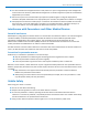
DEVICE ACTIVATION AND INSTALLATION 1. 2. 3. Remove the power supply cover (not shown). To do this, slide the lock down and hold it while you lift off the cover. Insert the latch on the blade into the notch on the power supply. Slide the lock down and hold it while you press the blade in place. Then, release it. 1 - Latch 2 - Notch 3 - Sliding lock Connecting Antennas, Cables, and Power To cable your device. 1. 2. 3. 4. 5. 6. Connect your antenna to the SMA connector, labelled ANT.
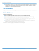
DEVICE ACTIVATION AND INSTALLATION ■ Verify the location has a strong signal strength. ■ Position the device so the antenna is always vertical and pointing upward. ■ Use the dimensions in the following image to space screw holes. ■ Use either #4 or #6 pan head screws. Installing Drivers If your device has a SIM card, install it before installing drivers. For Linux: This device is compatible with kernel 2.6 and higher. It uses the standard CDC-ACM driver.
DEVICE ACTIVATION AND INSTALLATION 8. 9. 10. 11. 12. 13. Click Have Disk. Browse to the Drivers folder. Select MTSMCIP_MTCMRIP.INF and click Open. Select your device from the list and click Next. Choose the COM Port your device is connected to and click Next. Click Finish to complete the install. Verifying that Modem Installed Successfully in Windows To verify that device installed correctly: 1. 2. In the Phone and Modem Options window, highlight your modem and click Properties.
BASIC OPERATIONS Basic Operations Device Phone Number Every device has a unique phone number. Your service provider supplies a phone number when you activate your account, or if your device has a SIM card, the phone number may be on it. Wireless service provider implementation may vary. Consult with your service provider to get the phone number for your device. Sending AT Commands AT commands allow you to configure, operate, and query your device.
BASIC OPERATIONS 6 6.4% to 12.8% 7 More than 12.8% 99 Not known or not detectable Note: Signal strength of 10 or higher is needed for successful packet data sessions. Example A example response to AT+CSQ: +CSQ: 15,1 Checking Network Registration Before establishing a packet data connection, verify the is device registered on the network. To do this enter the network registration report read command: AT+CREG? If the device returns: +CREG: 0,1 The device is registered.
BASIC OPERATIONS Creating a Windows Dial-Up Connection Each version of the Windows operating system has different steps for creating dial-up Internet connections. Consult Windows Help for the specific steps for your version. You may need the phone number, username, and password for your carrier. Setting the Access Point Number (APN) in Modem's Properties Some devices require an Access Point Number.
BASIC OPERATIONS Enter: M Response: MU Enter: D Response: M Enter: S Response: S Recovery To do this manually: 1. 2. 3. 4. 46 Shut off the device. Press Caps Lock and hold down M. Turn on the device. MU displays. PressD and S quickly.
REGULATORY STATEMENTS Regulatory Statements EMC, Safety, and R&TTE Directive Compliance The CE mark is affixed to this product to confirm compliance with the following European Community Directives: Council Directive 2004/108/EC of 15 December 2004 on the approximation of the laws of Member States relating to electromagnetic compatibility; and Council Directive 2006/95/EC of 12 December 2006 on the harmonization of the laws of Member States relating to electrical equipment designed for use within certain v
REGULATORY STATEMENTS This device complies with Industry Canada RSS Appliance radio exempt from licensing. The operation is permitted for the following two conditions: 1. 2. the device may not cause harmful interference, and the user of the device must accept any interference suffered, even if the interference is likely to jeopardize the operation. Le présent appareil est conforme aux CNR d'Industrie Canada applicables aux appareils radio exempts de licence.
ENVIRONMENTAL NOTICES Environmental Notices Waste Electrical and Electronic Equipment Statement WEEE Directive The WEEE Directive places an obligation on EU-based manufacturers, distributors, retailers, and importers to takeback electronics products at the end of their useful life. A sister directive, ROHS (Restriction of Hazardous Substances) complements the WEEE Directive by banning the presence of specific hazardous substances in the products at the design phase.
ENVIRONMENTAL NOTICES REACH Statement Registration of Substances After careful review of the legislation and specifically the definition of an “article” as defined in EC Regulation 1907/2006, Title II, Chapter 1, Article 7.1(a)(b), it is our current view Multi-Tech Systems, Inc. products would be considered as “articles”. In light of the definition in § 7.
ENVIRONMENTAL NOTICES Restriction of the Use of Hazardous Substances (RoHS) Multi-Tech Systems, Inc Certificate of Compliance 2011/65/EU Multi-Tech Systems confirms that its embedded products comply with the chemical concentration limitations set forth in the directive 2011/65/EU of the European Parliament (Restriction of the use of certain Hazardous Substances in electrical and electronic equipment - RoHS).
ENVIRONMENTAL NOTICES Information on HS/TS Substances According to Chinese Standards In accordance with China's Administrative Measures on the Control of Pollution Caused by Electronic Information Products (EIP) # 39, also known as China RoHS, the following information is provided regarding the names and concentration levels of Toxic Substances (TS) or Hazardous Substances (HS) which may be contained in Multi-Tech Systems Inc.
ENVIRONMENTAL NOTICES Information on HS/TS Substances According to Chinese Standards (in Chinese) 依照中国标准的有毒有害物质信息 根据中华人民共和国信息产业部 (MII) 制定的电子信息产品 (EIP) 标准-中华人民共和国《电子信息产品污染 控制管理办法》(第 39 号),也称作中国 RoHS, 下表列出了 Multi-Tech Systems, Inc.
INDEX Index A E Access Point Number ...............................................44 45 account activation.........................................................38 activation cellular devices.........................................................38 antenna .........................................................................33 CDMA .......................................................................32 connecting ...............................................................40 EV-DO..........
INDEX L PTCRB ............................................................................31 LED ................................................................................11 Linux ..............................................................................45 R M maintenance .................................................................10 maximum current .........................................................23 modem safety ...................................................................
INDEX USB cable ......................................................................40 user responsibility.........................................................10 56 V vehicle power...........................................................34 40 vehicle safety ..................................................................9 verify device setup.............................................................