Multi-Tech IP Connectivity Embedded SocketModem IP (MT2456SMI-IP) MultiConnect SS w/IP (MTS2SA-T, MTS2SA-T-R) External Wireless MultiModem CDMA w/IP (MTCBA-C-IP-xx) MultiModem CDMA, EDGE, GPRS with GPS Functionality (MTCBA-x-GP) Command Line Interface & Application Examples Reference Guide
Copyright and Technical Support Multi-Tech Systems, Inc. IP Commands Reference Guide for the following products: Embedded SocketModem IP (MT2456SMI–IP) MultiConnect SS w/IP (MTS2SA-T, MTS2SA-T-R) External Wireless MultiModem CDMA w/IP (MTCBA–C–IP–xx) MultiModem CDMA, EDGE, GPRS with GPS Functionality (MTCBA-x-GP) S000368F Revision F Copyright This publication may not be reproduced, in whole or in part, without prior expressed written permission from MultiTech Systems, Inc. All rights reserved.
Revision History Revision History Revision Date A 01/12/05 B 03/23/05 C D E 05/05/05 08/31/05 10/06/05 F 01/18/06 Description Initial release. This document is a new publication for the MultiModem CDMA IP commands. This document replaces the separate SocketModem IP (MT2456SMI-IP) document of commands originally published in Developer's Guide S000307D. It also replaces the command section in the MultiConnect Serial-to-Serial Adapter (MTS2SAT and MTS2SA-T-R) document published in User Guide S000354A.
Table of Contents Table of Contents Chapter 1 – Managing and Configuring IP Modules .................................................................................................7 Two Ways to Login.....................................................................................................................................................7 Login Using TTY ................................................................................................................................................
Table of Contents Deleting Users......................................................................................................................................................92 PPP Configuration....................................................................................................................................................92 PPP Interface Related Parameters ..........................................................................................................................
Table of Contents Scenario 7 – Listing Directory Contents ................................................................................................................. 124 Scenario 8 – Listing Directory Contents ................................................................................................................. 124 Scenario 9 – Sending a File to the FTP Server ......................................................................................................
Chapter 1 – Managing and Configuring the IP module Chapter 1 – Managing and Configuring IP Modules Two Ways to Login Login Using TTY • Use TTY to configure your IP module for the first time. Configure the host serial port using the defaults listed below: Baud: 115.2K Data: 8 Parity: N Stop: 1 Flow-Control: None • Press the Enter key three times to get to the Login prompt. • At the Login prompt, type admin. At the Password prompt, type admin. Important: The user name and password are case sensitive.
Chapter 2 – Command Line Interface (CLI) Chapter 2 – IP Command Line Interface (CLI) The commands of the IP modules are grouped based on the functionality. • • • • • • • • • • General Setup Commands IP Setup Commands Serial Setup Commands PPP Setup Commands HTTP Setup Commands SMTP Setup Commands POP3 Setup Commands FTP Client Setup Commands SNTP Client Setup Commands DDNS (Dynamic DNS) Client Setup Commands General Notes • • • • • Required command parameters are indicated between < >.
Chapter 2 – Command Line Interface (CLI) General Setup Commands General setup of an IP module is port-independent (physical s0, s1 etc.). The following command set is used to set the global configuration.
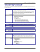
Chapter 2 – Command Line Interface (CLI) General Commands – Setup Command Syntax Description Default Value Success Error restore session On Telnet dialout, the control is transferred to the command parser passing the escape sequence “+++ inet”. Invoking “restore session” would resume the Telnet dialout exiting the command parser. NA OK 1. Too few arguments Possible arguments are: default-config session 2.
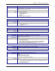
Chapter 2 – Command Line Interface (CLI) General Commands – Setup Command Syntax Description Default Value Success Error user delete Delete the user name from the group. NA OK 1. Too few arguments “Too few arguments. Possible value(s) are username followed by password“ 2. Unable to delete the user name “user ‘username‘ does not exist“ Command Syntax Description Default Value Success Error user password Change the password for a user. NA OK 1.
Chapter 2 – Command Line Interface (CLI) General Commands – Setup Command Syntax Description Default Value Success Error set date
- Sets the system date. Jan 1 1970 OK 1. Too few arguments Usage: set date DD/MM/YYYY Type 'set date ?' for more information Error: Date in DD/MM/YYYY format Too few arguments.
Chapter 2 – Command Line Interface (CLI) General Commands – Show Command Syntax Description Default Value Success Error Command Syntax Description Default Value Success Error Command Syntax Description Default Value Success Error Command Syntax Description Default Value Success Error show buildrun Command Line Configuration - History. Upon invoking any command, either through Telnet or Serial TTY, the command is added to the buildrun file. This is very useful in case of version updates. NA OK 1.
Chapter 2 – Command Line Interface (CLI) General Commands – Show Command Syntax Description Default Value Success Error show sys-info Displays the system related information. • Hardware information • System Uptime • Memory Utilization • Flash Memory Map NA OK 1. Too few arguments Too few arguments. Possible argument(s) are: configuration ip serial sys-info date ppp statistics time 2.
Chapter 2 – Command Line Interface (CLI) IP Commands – Setup IP Setup Commands Command Syntax Description Default Value Success Error set ip dns Enables/disables the DNS client. Enabled OK 1. Too few arguments “Usage: set ip dns Type ‘set ip dns ?’ for more information” 2. Invalid string Type ‘set ip dns ?’ for more information” Command Syntax Description Default Value Success Error set ip hostname Sets the host name of the IP module. “IP module” OK 1.
Chapter 2 – Command Line Interface (CLI) IP Commands – Setup Command Syntax Description Default Value Success Error set ip syslogd-server Sets the remote syslog server's IP address. 0.0.0.0 OK 1. Too few arguments “Usage: set ip syslogd-server Type ‘set ip syslogd-server ?’ for more information” 2.
Chapter 2 – Command Line Interface (CLI) IP Commands – Setup Command Syntax Description Default Value Success Error set ip telnet escape-string The Telnet Server scans for this escape sequence and transfers the control to the command parser. By default, the Telnet Server scans for “+++inet”. +++ inet OK 1. Too few arguments “Usage: set ip telnet escape-string Type ‘set ip telnet escape-string ?’ for more information” 2.
Chapter 2 – Command Line Interface (CLI) IP Commands – Setup Command Syntax Description Default Value Success Error Command Syntax Description Default Value Success Error Command Syntax Description Default Value Success Error Command Syntax Description Default Value Success Error set ip telnet-port This Telnet-port corresponds to the port number that the IP module will wait on for configuring the box. By default the port number is TCP 23. You have the option to change this port number.
Chapter 2 – Command Line Interface (CLI) IP Commands – Setup Command Syntax Description Default Value Success Error set ip udp udp-inactivity-timeout If the UDP session is inactive for ‘t’ secs, the connection is terminated. This functionality is applicable only if “set udp inactivity” is enabled. (Refer to the ’set ip udp inactivity’ command). 300 OK 1. Too few arguments “Usage: set ip udp udp-inactivity-timeout Type ‘set ip udp udp-inactivity-timeout ?’ for more information” 2.
Chapter 2 – Command Line Interface (CLI) Serial Commands – Setup Serial Setup Commands Command Syntax Description Default Value Success Error set serial auto-dialin This command globally enables serial auto dial-in support. Notes: • This feature provides a dial-in session to the serial device connected to s0 through the IP-enabled modem port (s1) • Also, dial-in can be done only after PPP is up and has acquired an IP address on the modem's (s1) port. Disabled OK 1.
Chapter 2 – Command Line Interface (CLI) Serial Commands – Setup Command Syntax Description Default Value Success Error Command Syntax Description Default Value Success Error Command Syntax Description Default Value Success Error linkup [serial interface] Valid serial interface – Modem port s1 Establishes a physical link and PPP on the modem port. This command is relevant only when the serial interface is a dialing end with dialing-trig-mode configured as command.
Chapter 2 – Command Line Interface (CLI) Serial Commands – Setup Command Syntax Description Default Value Success Error Command Syntax Description Default Value Success Error set serial [s0] auto-dialin-port [port_num] Command to specify the auto dial-in port number. Note: [port_num] is optional here. If port_num is not specified, the standard port 23 of the Telnet protocol shall be used. This command is valid only for device port s0 23 OK 1.
Chapter 2 – Command Line Interface (CLI) Serial Commands – Setup Command Syntax Description Default Value Success Error Command Syntax Description Default Value Success Error set serial [s0] auto-dialin trig-mode This mode is applicable only when auto dial-in is enabled on the serial port s0. This command is valid only for device port s0. Parameter Description char Initiate a session (Telnet) to the auto-dialin-host, only on a reception of a character on the serial port s0.
Chapter 2 – Command Line Interface (CLI) Serial Commands – Setup Command Syntax Description Default Value Success Error Command Syntax Description Default Value Success Error Command Syntax Description Default Value Success Error set serial [s0] auto-dialin-delimiter Specifies the auto dial-in delimiter. This command is valid only for device port S0. $ OK 1.
Chapter 2 – Command Line Interface (CLI) Serial Commands – Set NMEA Filtering Command Syntax Description Default Value Success Error Command Syntax Description Default Value Success Error Command Syntax Description Default Value Success Error set serial [s0] auto-dialin filter Enables/disables the filtering of data from serial to network, after execution of chatscript during the course of two-way communication in raw-mode for auto-dialinfiltering enhancement.
Chapter 2 – Command Line Interface (CLI) Serial Commands – Set NMEA Filtering Command Syntax Description Default Value Success Error Command Syntax Description Default Value Success Error Command Syntax Description Default Value Success Error set serial [s0] auto-dialin filter timer < 0 - 65535> Specifies the timer value in between successful sends in auto dial-in when filtering is enabled. This command is valid only for device port s0. 0 OK 1.
Chapter 2 – Command Line Interface (CLI) Serial Commands – Setup Command Syntax Description Default Value Success Error Command Syntax Description Default Value Success Error Command Syntax Description Default Value Success Error set serial [s0] auto-dialout Enables/disables connectivity to the serial device from the IP-enabled built-in modem serial interface. This command is valid only for device port s0. Enabled OK 1.
Chapter 2 – Command Line Interface (CLI) Serial Commands – Setup Command Syntax Description Default Value Success Error set serial [s0/s1] baud-rate Sets the serial baud rate. 115200 OK 1. Too few arguments “Usage: set serial s0/s1 baud-rate Type ‘set serial s0/s1 baud-rate ?’ for more information” 2.
Chapter 2 – Command Line Interface (CLI) Serial Commands – Setup Command Syntax Description set serial [s0/s1] buffer-time <0/t secs> This command is related to the ‘set serial s0/s1 buffer-datasize’ command. The buffering of data shall either wait for datasize configured (in the previous command) or time t secs. How to Read the Examples Below: Line 1 - Sl Line 2 - Buffer-datasize Line 3 - Buffer-time (secs) Line 4 – Descriptions Example 1 1 0 - Default 0 - Default No buffering.
Chapter 2 – Command Line Interface (CLI) Serial Commands – Setup Command Syntax Description Default Value Success Error Set serial [s0/s1] connect-type Sets the connect type of the serial port to direct/modem connect. Modem port (s1) will always have connect-type as modem since it is a built-in modem Direct OK 1. Too few arguments “Usage: set serial s0/s1 connect-type Type ‘set serial s0/s1 connect-type ?’ for more information” 2.
Chapter 2 – Command Line Interface (CLI) Serial Commands – Setup Command Syntax Description Default Value Success Error Command Syntax Description Default Value Success Error Command Syntax Description Default Value Success Error Command Syntax Description Default Value Success Error Command Syntax Description Default Value Success Error Set serial [s0/s1] flow-control Set the flow-control of the serial port. By default flow-control is disabled on the serial port. rts-cts OK 1.
Chapter 2 – Command Line Interface (CLI) Serial Commands – Setup Command Syntax Description Default Value Success Error Command Syntax Description Default Value Success Error Command Syntax Description Default Value Success Error Command Syntax Description Default Value Success Error set serial [s0/s1] modem dial-suffix Sets the Modem Dial-suffix. Triggers for a reboot upon save. Note: The configured modem strings takes precedence over the MODEM.CNF ^M OK 1.
Chapter 2 – Command Line Interface (CLI) Serial Commands – Setup Command Syntax Description Default Value Success Error set serial [s0/s1] modem hangup-string Sets the Modem hang-up string. Triggers for a reboot upon save. +++ATH0 OK 1.
Chapter 2 – Command Line Interface (CLI) Serial Commands – Setup Command Syntax Description Default Value Success Error set serial [s0/s1] parity Sets parity to even/odd/none. None OK 1. Too few arguments “Usage: set serial s0/s1 parity Type ‘set serial s0/s1 parity ?’ for more information” 2.
Chapter 2 – Command Line Interface (CLI) Serial Commands – Setup Command Syntax Description Default Value Success Error set serial [s0/s1] stop-bits <1/1.5/2> Sets the stop bits. 1 OK 1. Too few arguments “Usage: set serial s0/s1 stop-bits <1/1.5/2> Type ‘set serial s0/s1 stop-bits ?’ for more information” 2. Invalid stop-bit setting “ERROR: Stop-bit supported : [1, 1.
Chapter 2 – Command Line Interface (CLI) Serial Commands – Show Command Syntax Description Default Value Success Error Command Syntax Description Default Value Success Error show serial [s0] auto-dialin-chat-script Displays the Expect and Send sequence for the serial port S0. NA OK 1. Too few arguments Possible value(s) are auto-dialin-chat-script statistics modem-configuration configuration chat-script show serial modem country code This command is supported on s1 only.
Chapter 2 – Command Line Interface (CLI) PPP Commands – Setup PPP Setup Commands Note: All PPP Commands use the ppp0 interface, which corresponds to the modem port s1. Command Syntax Description Default Value Success Error set ppp authentication Enables/disables PPP Authentication. Disabled OK 1. Too few arguments Possible argument(s) are: enable disable 2. Invalid string Invalid argument. Valid argument(s) are: enable disable 3.
Chapter 2 – Command Line Interface (CLI) PPP Commands – Setup Command Syntax Description Default Value Success Error Command Syntax Description Default Value Success Error Command Syntax Description Default Value Success Error Command Syntax Description Default Value Success Error set ppp dialing-max-retries <0-100> Configures the maximum number of dialing retries. Maximum dialing retry is 100 5 OK 1.
Chapter 2 – Command Line Interface (CLI) PPP Commands – Setup Command Syntax Description Default Value Success Error set ppp local-ip-addr mask During IPCP negotiations, the configured IP address is sent for the local interface. In the case where the peer is requested to provide the IP address, it can be configured as 0.0.0.0 0.0.0.0 255.255.255.0 OK 1. Too few arguments Possible arguments are: IP Address Mask 2.
Chapter 2 – Command Line Interface (CLI) PPP Commands – Setup Command Syntax Description Default Value Success Error set ppp ping-keepalive Enables/disables the ping-keepalive feature. Disabled OK 1. Too few arguments Too few arguments. Possible argument(s) are: ping-host ping-interval ping-no-of-packets Possible value(s) are enable or disable. 2.
Chapter 2 – Command Line Interface (CLI) PPP Commands – Setup Command Syntax Description Default Value Success Error set ppp ping-keepalive ping-no-of-packets <1-100> Sets the number of ping packets to be sent to the server per attempt. Maximum number of packets is 100. 10 packets OK 1. Too few arguments Too few arguments. Possible argument(s) are: ping-host ping-interval ping-no-of-packets Possible value(s) are enable or disable 2.
Chapter 2 – Command Line Interface (CLI) PPP Commands – Show Command Syntax Description Default Value Success Error Command Syntax Description Default Value Success Error Command Syntax Description Default Value Success Error Command Syntax Description Default Value Success Error show ppp ppp0 configuration Displays: PPP Status (enabled/disabled) Authentication status Authentication type Username and password for authentication Compression status Compression type IPCP Mode Local IP Address Remote IP Ad
Chapter 2 – Command Line Interface (CLI) PPP Commands – Show Command Syntax Description Default Value Success Error show ppp trace Displays the last ppp negotiations. OK 1. Too few arguments Possible argument(s) are: configuration ip-addr 2. Invalid argument Invalid argument Valid argument(s) are: configuration ip-addr link-status statistics trace link-status statistics trace Command Line Interface and Application Examples for Multi-Tech Systems, Inc.
Chapter 2 – Command Line Interface (CLI) HTTP Server Commands – Setup HTTP Server Commands The commands in this section are listed in the order in which they might be used. Command Syntax Description Default Value Success Error set ip http-page This parameter is used by the http server to host the default HTML index or hostdefined http-serial-s0 HTML page. Default OK 1. Too few arguments “Usage: set ip http-page Type set ip http-page ?” 2.
Chapter 2 – Command Line Interface (CLI) HTTP Server Commands – Show Command Syntax Description Default Value Success Error show http configuration Displays the HTTP related configurations. OK 1. Too few arguments “ERROR: Too few arguments Type 'show http configuration ?' for more information” Command Syntax show device-parameter P where n = 0 to 99. Displays the value of the requested parameter from the IP module. OK 1.
Chapter 2 – Command Line Interface (CLI) SMTP Client Commands – Setup SMTP Client – Commands The commands in this section are listed in the order in which they might be used. Command Syntax Description Default Value Success Error set send-mail smtp-server-name Sets the SMTP server name or IP address. Server names must be such that they can be resolved by the DNS. NULL OK 1.
Chapter 2 – Command Line Interface (CLI) SMTP Client Commands – Setup Command Syntax Description Default Value Success Error Command Syntax Description Default Value Success Error set send-mail to-address where n = 1 to 5. Sets the email-address as one of the primary addressee. This is the default email address to which email messages are sent. NULL OK 1.
Chapter 2 – Command Line Interface (CLI) SMTP Client Commands – Setup Command Syntax Description Default Value Success Error set send-mail password Sets the password that smtp-client will use for authentication. with the server NULL OK 1. Too few arguments Possible value(s) are valid password. Command Syntax send-mail [-b] [-t ] [-c ] [-s ] [-d ] Triggers the SMTP Client application.
Chapter 2 – Command Line Interface (CLI) POP3 Client Commands – Setup POP3 Client Commands Command Syntax Description Default Value Success Error Command Syntax Description Default Value Success Error set recv-mail server-name This parameter is set by the host to establish the POP3 connection for receiving the email from the remote server. This also needs DNS to be enabled on the IP module. None OK 1.
Chapter 2 – Command Line Interface (CLI) POP3 Client Commands – Setup Command Syntax Description Default Value Success Error Command Syntax Description Default Value Success Error Command Syntax Description Default Value Success Error Command Syntax Description Default Value Success Error Command Syntax Description Default Value Success Error recv-mail list [index] This command retrieves list of emails from the mailbox.
Chapter 2 – Command Line Interface (CLI) POP3 Client Commands – Show Command Syntax Description Default Value Success Error recv-mail unique-id-listing [index] Displays the unique ID listing from the server in the order below: . If index is specified, only the corresponding unique ID is displayed. If index is not specified, all unique IDs in the mail box are displayed. OK 1.
Chapter 2 – Command Line Interface (CLI) FTP Client Commands – Setup FTP Client Commands Command Syntax Description Default Value Success Error set ftp device login [password [account ] Sets/clears the device login name, password and account password details that will be used by FTP for automatic authentication.
Chapter 2 – Command Line Interface (CLI) FTP Client Commands – Setup Command Syntax Description Default Value Success Error ftp < [-l [-d ]] [-t [-d ] [-n ] [-s ]] [-a [-d ] [-n ] [-s ]] [-r [-d ] [-n ]] > [-p] [-m] Triggers the ftp client to establish the ftp session with the remote server and to perform the required action according to the specified option.
Chapter 2 – Command Line Interface (CLI) SNTP Client Commands – Setup SNTP Client – Commands Command Syntax Description Default Value Success Error Command Syntax Description Default Value Success Error set sntp client Starts the SNTP Client to contact the configured server on UDP port 123 and set the local time. Disable OK 1.
Chapter 2 – Command Line Interface (CLI) SNTP Client Commands – Setup Command Syntax Description Default Value Success Error set sntp-client polling-time where value = 2 to 1440 Sets the polling time at which SNTP client requests the server to update the time. 300 OK 1. Invalid arguments "error: Invalid Polling time" 2.
Chapter 2 – Command Line Interface (CLI) SNTP Client Commands – Setup Command Syntax Description Default Value Success Error Command Syntax Description Default Value Success Error Command Syntax Description Default Value Success Error Command Syntax Description Default Value Success Error Command Syntax Description Default Value Success Error set sntp-client daylight-saving start-month where month = january, february .... december Sets the start month to use during the Day Light Saving Mode.
Chapter 2 – Command Line Interface (CLI) SNTP Client Commands – Setup Command Syntax Description Default Value Success Error set sntp-client daylight-saving end-time where hh = 00 to 23 mm = 00 to 59 Sets the end time to use during the Day Light Saving Mode. 02:00 OK 2. Invalid arguments "error: Invalid end time“ 2.
Chapter 2 – Command Line Interface (CLI) DDNS Client Commands – Setup Dynamic DNS Client Commands (DDNS) Command Syntax Description Default Value Success Error set ip ddns Enables/disables the DDNS client. Disabled OK 1. Too few arguments Too few arguments. Possible argument(s) are: checkip-port checkip-server domain max-retries password port server system update-interval user Possible value(s) are enable or disable 2.
Chapter 2 – Command Line Interface (CLI) DDNS Client Commands – Setup Command Syntax Description Default Value Success Error set ip ddns domain Sets the domain name whose ip-address is to be updated. NULL OK 1. Too few arguments “Usage: set ip ddns domain Type ‘set ip ddns domain ?’ for more information” 2.
Chapter 2 – Command Line Interface (CLI) DDNS Client Commands – Setup Command Syntax Description Default Value Success Error set ip ddns system Sets the DDNS system to be used by the DDNS client dynamic OK 1. Too few arguments “Usage: set ip ddns system Type ‘set ip ddns system ?’ for more information” 2.
Chapter 2 – Command Line Interface (CLI) RAW TCP/UDP Socket Support Setup Commands Command Syntax Description Default Value Success Error Command Syntax Description Default Value Success Error Command Syntax Description Default Value Success Error socket tcp Opens a TCP client socket and attempts to connect it to the specified remote port on a specified remote server. The remote server should be set with a DNS resolvable name or IP address.
Chapter 2 – Command Line Interface (CLI) RAW TCP/UDP Socket Support – Setup Commands Command Syntax Description Default Value Success Error Command Syntax Description Default Value Success Error Command Syntax Description Default Value Success Error socket listlisten [-s] [-d] -s : When the socket-only option is specified, it displays the TCP server socket handle, local port, backlog and TCP listen socket handles.
Chapter 2 – Command Line Interface (CLI) RAW TCP/UDP Socket Support – Setup Commands Command Syntax Description Default Value Success Error Command Syntax Description Default Value Success Error Command Syntax Description Default Value Success Error Command Syntax Description Default Value Success Error socket recv [-s ] Retrieves the exact size of data received followed by data stream from the specified socket handle (corresponds to TCP or UDP socket).
Chapter 3 – Setting Country Codes Using the CLI Chapter 3 – Setting Country or Region Codes Using the CLI The Default Country or Region Code is B5. If You Want to Change the Country or Region Code, Use the Command Line Interface: Command Syntax Description Default Value Success Error set serial s1 modem country-code value Sets the modem country/region code value to . This command is valid only for port s1. Applicable only if the country-code type is set to code. OK 1.
Chapter 4 – Scenario Setup Prerequisites Chapter 4 – Scenario Setup Prerequisites This chapter covers prerequisite tasks, those tasks or configurations that must be completed before you can set up certain operating scenarios. Prerequisites are referenced throughout the rest of this document. IP Communication Interfaces and Conventions The Serial Interface ports, s0 and s1, correspond to Device Port and Modem Port respectively. This convention is used throughout this document. Serial Ports 1. 2.
Chapter 4 – Scenario Setup Prerequisites IP Modes of Operation The IP module can function in two modes: • Transparent Mode When the IP module is configured to function in the modem operation mode, it functions as a modem. The Host/Serial device connected on the device port can use the IP module as a modem in transparent mode. Refer to Chapter 7 for application examples that use Transparent Mode.
Chapter 4 – Scenario Setup Prerequisites Physical Link Established over the Modem Port The PPP link must be opened up on the modem port for any application such as SMTP Client, HTTP Server, POP3 Client, etc. to function. Wireless IP implementation provides three mechanisms for establishing the physical link over the modem port: • Dialing-trig-mode NONE • Dialing-trig-mode DTR • Dialing-trig-mode Command Choose the method you desire by configuring the physical link through the Command Line Interface (CLI).
Chapter 5 – Network-to-Serial Connectivity Using Dialout Chapter 5 – Network-to-Serial Connectivity Using Dialout Network-to-Serial Connectivity Using the Telnet / UDP Dialout Feature This is an example of a Telnet or UDP client on an network connecting to a remote serial device. The IP module acts as a Terminal Server using the Telnet or UDP dialout feature. This feature allows you to access the serial port and establish two-way traffic between the Telnet/Raw-TCP/UDP client and the serial device.
Chapter 5 – Network-to-Serial Connectivity Using Dialout Prerequisites Telnet Auto-Dialout Mandatory Configuration Settings The following items must be configured in order to use the dial-out feature: • Disable the Host Interaction Mode to restrict Telnet-Dial-Out and PPP. # set serial s0 host-interaction-mode disable • Enable Auto dial-out globally on all the serial ports. # set ip auto-dialout enable • Enable Auto dial-out on the serial port s0.
Chapter 5 – Network-to-Serial Connectivity Using Dialout • Set the Data bits for the serial port s0 to be taken for a Dialout session. # set serial s0 data-bits <7/8> • Set the Stop bits for the serial port s0 to be taken for a Dialout session. # set serial s0 stop-bits <1/1.
Chapter 5 – Network-to-Serial Connectivity Using Dialout Scenario 1 – Manual Dialout Connect to the IP module using a Telnet Client on port 5000 (configuration port). At the command prompt, invoke # dialout serial s0. Once the session is opened successfully, there can be two-way traffic between the Telnet client and the serial device. • You can switch from Command Prompt to Dialout session using the restore session command.
Chapter 5 – Network-to-Serial Connectivity Using Dialout Scenario 2 – Auto Dialout In this scenario, the Auto Dialout session in Telnet mode is opened using a Telnet client. Prerequisites RAW mode (global and each port) MUST BE DISABLED using the Optional Configuration Commands. A Telnet client can open an auto Dialout session by specifying the configured auto-dialout port. Once the session is opened successfully, there can be two-way traffic between the Telnet session and the remote serial device.
Chapter 5 – Network-to-Serial Connectivity Using Dialout Scenario 3 – Auto Dialout in RAW Mode In this scenario, the Auto-Dialout session in RAW mode is opened using a RAW-TCP client. Prerequisites RAW mode (Global and each port) MUST BE ENABLED using the Optional Configuration Commands. The Auto Dialout session can be opened by a RAW-TCP client by specifying the auto-dialout configured port.
Chapter 5 – Network-to-Serial Connectivity Using Dialout Scenario 4 – Dialout Serial s1 In this scenario, the dialout session to serial s1 (built-in modem) is opened. • The dialout serial s1 command helps to send the AT command to the modem and get a response without being in the modem-bypass mode. • When the dialout command is issued, it kills the application running on s1. For example, if PPP is established in dialing or answering mode, it is killed when the dialout command is issued.
Chapter 5 – Network-to-Serial Connectivity Using Dialout Scenario 5 – Auto Dialout Using UDP In this scenario, the Auto Dial-out session in UDP mode is initiated by an external UDP Client. The UDP Client can send/receive data to/from the UDPServer residing at the IPModule. . UDP client sends to 192.168.2.1 5000 192.168.2.210 PPP UDP Server (5000) IPModule 192.168.2.
Chapter 6 – Serial-to-Network Connectivity Using Serial Dial-in Chapter 6 – Serial-to-Network Connectivity Using Serial Dial-in Introduction The auto dial-in feature enables the IP module to act as a Telnet or UDP client thus facilitating the serial device to access any Telnet/terminal servers on the IP network (over the built-in modem interface). Once the session (Serial Client to Server) is opened successfully, it allows two-way traffic between the serial device and the remote server.
Chapter 6 – Serial-to-Network Connectivity Using Serial Dial-in UDP Mandatory Configuration Settings The following items must be configured in order to use the UDP auto-dial-in feature: • Enable Auto dial-in globally on all the serial ports. # set serial auto-dialin enable • Enable Auto dial-in on the serial port s0. # set serial s0 auto-dial-in enable • Set the Auto dial-in protocol. # set serial s0 auto-dialin-protocol udp • Set the Auto dial-in Server IP Address.
Chapter 6 – Serial-to-Network Connectivity Using Serial Dial-in Scenario 1 – Manual Serial Dial-in Login to the Command prompt from the serial side. Invoke # telnet at the command prompt. Once the session is opened successfully, there can be two-way traffic between the serial device and the remote server. • You can switch from Command Prompt to Dial-in session using the restore session command. • You can switch from Dial-in session to Command Prompt using .
Chapter 6 – Serial-to-Network Connectivity Using Serial Dial-in Scenario 2 – Auto Dial-in in Telnet Mode This example shows how to setup a serial auto dial-in session in Telnet mode. The auto dial-in session is opened by Telnet client embedded in the IP module to the configured server on a configured port. Once the session is opened successfully, there can be two-way traffic between the serial device and the remote server.
Chapter 6 – Serial-to-Network Connectivity Using Serial Dial-in Scenario 3 – Auto Dial-in Session in RAW Mode This scenario shows how to configure an auto dial-in session in RAW mode.
Chapter 6 – Serial-to-Network Connectivity Using Serial Dial-in Scenario 4 – Serial Tunneling Mode The scenario shows how to setup serial-to-serial tunneling using two MTS2SA (Serial-to-Serial) adapters/device servers, two external modems, and two phone lines. Assume both MTS2SAs are using factory default settings.
Chapter 6 – Serial-to-Network Connectivity Using Serial Dial-in Scenario 5 – Auto-Dialin Enhancement for Use with GPS Tracking Software This scenario describes the TCP session establishment, auto-dialin-chat-script negotiation, and data transfer between the GPS receiver and the GPS tracker server. Connection establishment and data transfer between the server and the host In the figure above, the TCP/IP server is the GPS server and the host is the GPS receiver.
Chapter 6 – Serial-to-Network Connectivity Using Serial Dial-in SocketModem IP basic PPP link establishment Commands # set serial s1 stop-bits 1 # set serial s1 baud-rate 115200 # set serial s1 data-bits 8 # set serial s1 parity none # set serial s1 flow-control rts-cts # set serial s1 connect-type modem # set serial s1 modem dial-number # set serial s1 modem dialing-trig-mode # set ppp ppp0 ipcp-mode client-only # set ppp ppp0 username “socketmodem” # set ppp ppp0 password “socke
Chapter 6 – Serial-to-Network Connectivity Using Serial Dial-in Scenario 6 – Serial Auto Dial-in Using UDP This example shows how to setup a serial auto dial-in session in UDP mode. The auto dial-in session is opened by the UDP client embedded in the IP module to the configured server on a configured port. Once the session is opened successfully, there can be two-way traffic between the serial device and the remote server.
Chapter 6 – Serial-to-Network Connectivity Using Serial Dial-in Scenario 7 – Auto Dial-in Enhancement for NMEA Filtering This scenario shows how to configure an auto dial-in session in RAW TCP mode for NMEA filtering. This enhancement is a feature addition to Scenarios 3 and 5 explained above.
Chapter 6 – Serial-to-Network Connectivity Using Serial Dial-in # set serial s0 auto-dialin-chat enable # set serial s0 auto-dialin-chat-script 1 "\"SEND PASSWORD\"" "SECRET" # set serial s0 auto-dialin-chat-script 2 "OK" \"\" # set serial s0 auto-dialin-delimiter \$ # set serial s0 auto-dialin-prefix "0001" # set serial s0 stop-bits 1 # set serial s0 baud-rate 115200 # set serial s0 data-bits 8 # set serial s0 parity none # set serial s0 flow-control rts-cts # set serial s1 stop-bits 1 # set serial s1 baud
Chapter 7 – Modem (Transparent) Mode Chapter 7 – Modem (Transparent) Mode Introduction In the modem mode (also called transparent mode), raw data is communicated between serial ports 1 and 2.
Chapter 7 – Modem (Transparent) Mode Scenario 1 – IP Module as a Modem In this scenario, once the physical link is up on the built-in modem interface; i.e., by dialing or answering, the serial device connected to the RS-232 interface (S0 of the target) can communicate to the device on the built-in modem interface (S1 of the target) and vice-versa.
Chapter 7 – Modem (Transparent) Mode Scenario 2 – Serial Tunneling in Transparent Mode In this scenario, two IP modules in transparent mode aid in the communication between two serial devices that are connected to the RS-232 interface (s0) of the IP modules. Serial tunneling is achieved in the transparent mode where raw data is communicated.
Chapter 7 – Modem (Transparent) Mode Scenario 3 – Transparent Mode by Bypassing Network Processor This scenario is for wireless modems only! Transparent mode by bypassing the Network Processor. (applicable only for wireless modems). In this scenario, raw data is communicated between serial ports at hardware level. The option to perform transparent mode with bypassing the processor is controlled with configuration command. In this scenario, once the physical link is up on the built-in modem interface; i.e.
Chapter 8 – Point-to-Point Protocol Chapter 8 – Point-to-Point Protocol Introduction Point-to-Point Protocol (PPP) is the Internet Standard for transmission of IP packets over serial links. This protocol is commonly used in serial links (asynchronous or synchronous) to transfer packets between two endpoints. These links provide full-duplex simultaneous bi-directional operation and are assumed to deliver packets in order.
Chapter 8 – Point-to-Point Protocol Prerequisites to Establishing a PPP Session Before establishing a PPP session, users should be added to the user database. The user name and password supplied by the remote peer will be authenticated using the local database. The following sections describe the commands to add / delete user names and passwords to the local database. Adding Users and Passwords Upon successful execution of this command, the IP module will return an OK or an error message.
Chapter 8 – Point-to-Point Protocol PPP Interface Related Parameters Enabling/Disabling Authentication This command enables or disables a PPP Authentication session. If Authentication is enabled, then the authentication protocol, the user name, and password should also be set: Command: # set ppp [interface] authentication Example: # set ppp ppp0 authentication enable OK Authentication Type - Protocol This command sets the Authentication type.
Chapter 8 – Point-to-Point Protocol Wakeup-on Call Feature This command enables or disables the wakeup-on call feature. Command: #set ppp wakeup-on-call This command sets the wakeup-on caller-ids Command: #set ppp wakeup-callerid Example: #set ppp ppp0 wakeup-callerid 1 „XXX:123“ User can configure 10 caller-ids for caller validation. The delay in seconds before the “PPP linkup” initiation after receiving a valid caller-id.
Chapter 8 – Point-to-Point Protocol Serial Interface Related Parameters Connect Type This command sets the connection type. A connection type can be either a direct connection or a connection through a modem. In case of a modem connection, the modem settings also have to be configured as described in the following sections.
Chapter 9 – HTTP Server Chapter 9 – HTTP Server Introduction The HTTP Server on the IP module supports hosting of embedded Web pages on behalf of the host. The hostdefined embedded pages support live host parameter monitoring and configuration update through a remote browser.
Chapter 9 – HTTP Server Setup and Configuration Prerequisite for Enabling the HTTP Server Before being able to access the IP module or the serial host through the Web browser, the HTTP support on the IP module needs to be enabled and configured. The following configuration is mandatory and can be configured using CLI either through serial or through Telnet. Mandatory Setup for HTTP Server set ip http enable Successful execution of this command starts the HTTP daemon thus enabling the HTTP server.
Chapter 9 – HTTP Server Configuration Modes The embedded HTTP Server on the IP module supports two configuration modes. This option is available when the http-page is set to serial (see Mandatory Setup instructions). • • Host Configuration Mode IP Module Configuration Mode (not supported at this point of time) In the Host Configuration Mode, the OEM’s embedded home page is sent to the remote browser. The page serves as a means of monitoring the host parameters live remotely.
Chapter 9 – HTTP Server Example: P0:temperature:I:1:65535:100 P1:username:S:8:50:IP module Definition of the parameters: P0 and P1 are two parameters that correspond to the names Temperature & username specified in the HTML page. I/S represents Integer and String respectively. 1 is the minimum value for the parameter P0 65535 is the maximum value for the parameter P0. 8 is the minimum number of characters for the parameter P1. 50 is the maximum number of characters for the parameter P1.
Chapter 9 – HTTP Server 2. The Embedded HTML Page The embedded Web page stored on the IP module consists of normal ASCII text HTML code, which can be generated using any HTML editing tool. The page can include scripts, links to remote Web sites, graphic images, text files, etc. A maximum 30 KB (uncompressed) of flash space for the OEM’s Home Page and an additional 10 KB maximum memory is reserved for the device parameter list.
Chapter 9 – HTTP Server Uploading the Web Page and Parameter List The Host Device Files (.HTML, default parameter List….) can be uploaded to the IP module using TFTP CLIENT. It is possible to upload these files in two different ways. In any case, file naming and file size conventions described previously must be followed. • Compressed and Zipped formats (tar.gz) or • Uncompressed individual files. Uploading Compressed and Zipped Files (http.tar.gz) In order to load files in the compressed (http.tar.
Chapter 9 – HTTP Server Monitoring and Configuring the Host through a Browser If you have successfully completed the preceding configuration sections and completed the uploading, you are now ready to View, Monitor, and Configure the Host through the Web browser. In order to view the device home page, enter the IP Address of the IP module into the URL Address bar. Example: http://192.168.2.1 The IP address 192.168.2.1 corresponds to the IP address of the IP module.
Chapter 10 – SMTP Client Chapter 10 – SMTP Client Introduction SMTP Client is used to establish a TCP session on an SMTP server running on port 25. SMTP Client supports sending ASCII text or MIME-encoded binary attachment emails with different media types and subtypes from the host/serial device through commands to the IP module. SMTP Client supports the following methods for sending emails: • To the hosts/email addresses specified in the command prompt. • To the hosts/email addresses pre-configured.
Chapter 10 – SMTP Client Scenario 1 – Sending a Text Email from the Command Prompt Issue the following command: send-mail -t ", " -c ", " -s "subject data" -d "Messagebody" A message is then given as shown in the figure below and the email is sent only to the to-addresses (if any) and the cc-addresses (if any) entered from the command prompt. The subject and message body are also taken from the command prompt. Notes 1.
Chapter 10 – SMTP Client Scenario 2 – Sending a Text Email Using Interactive Mode This scenario sends a text email with the message body is entered in interactive mode. Issue the following command: send-mail -t ", " -c ", " -s "subject data" The SMTP session then enters into interactive mode and requests that the message body be entered (see the figure below). After typing the message, type Ctrl+D to end the message.
Chapter 10 – SMTP Client Scenario 3 – Sending a Text Email Using Configuration and Interactive Mode This scenario sends a text email with: • The to-addresses, cc-addresses, and subject taken from the configuration and • The message body is entered in interactive mode. To support this scenario, you must configure the following details in addition to the mandatory configuration • • • Set subject data of maximum length 255 characters.
Chapter 10 – SMTP Client Scenario 4 – Sending a Text Email in Interactive Mode without Configuration The to-address, cc-address, and subject are NOT configured in this example. Issue the following command: send-mail The SMTP session then enters into interactive mode requesting the to-address, cc-address, subject and the message body to be entered. After entering a message, type Ctrl+D to end the message. The email is sent only to the entered to-addresses (if any) and cc-addresses (if any).
Chapter 10 – SMTP Client Scenario 5 – Sending a Mime Encoded Binary Attachment Using the Command Prompt Sending a Mime Encoded Binary Attachment with the email addresses, subject, and message body are taken from the command prompt.
Chapter 10 – SMTP Client Scenario 6 – Sending a Mime Encoded Binary Attachment Using Command Prompt and Interactive Mode Sending a Mime Encoded Binary Attachment With: • The to-address, cc-address, and subject entered through the command prompt • The message body entered in the Interactive Mode Issue the following command: send-mail -b -t ", " -c ", " -s "subject data" The SMTP session then enters into interactive mode requesting the message body as shown in
Chapter 10 – SMTP Client Scenario 7 – Sending a Mime Encoded Binary Attachment Using Pre-Configuration Sending a Mime Encoded Binary Attachment With: • The to-address, cc-address, and subject are pre-configured. • The message body is entered in the Interactive Mode. Configure the following details apart from the mandatory configuration: • Set subject data of maximum length 255 characters. Command: set send-mail subject "subject data" • Set to-addresses of maximum length 64 characters.
Chapter 10 – SMTP Client Scenario 8 – Sending a Mime Encoded Binary Email with Attachment Using Interactive Mode Issue the following command: send-mail -b The SMTP session then enters into interactive mode requesting the to-address, the cc-address, subject, and message body to be entered. After completion of the message, type Ctrl+D to end the message. The SMTP session enters into interactive mode requesting media-type, media-subtype, filename, filesize, and the attachment body as shown in the figure.
Chapter 11 – POP3 Client Chapter 11 – POP3 Client Introduction The IP module can be configured as a POP3 client to retrieve emails from a POP3 server.
Chapter 11 – POP3 Client Example of the show recv-mail configuration Use the show recv-mail configuration to check the configuration. +--------------------------------------------------------+ | pop3 configuration | +--------------------------------------------------------+ | server-name : 192.168.2.
Chapter 11 – POP3 Client Scenario 1 – Retrieving Emails The command recv-mail mail can be used to retrieve all the emails from a POP3 server. This command will retrieve all the email with headers, message body, and attachments. The command recv-mail mail , where n is the message number, can be used to retrieve the nth message. Scenario 2 – Retrieving the Number of Emails and the Total Email Size Use the command recv-mail stat to retrieve the number of emails and the total email size in octets.
Chapter 11 – POP3 Client Scenario 3 – Retrieving the Email List Use the command recv-mail list to retrieve the email list containing the message number and the size of the individual messages (in octets). The output is multi-lined. Use the command recv-mail list to retrieve the message size of the nth message. The output is multi-lined. Scenario 4 – Retrieving Emails Headers Use the command recv-mail header to retrieve the message header of all emails. The output is multi-lined.
Chapter 11 – POP3 Client Scenario 5 – Retrieving First t Lines To retrieve the first few lines of an email, use the command recv-mail top , where n is the message number and t is the number of lines to be retrieved. This command shows the message headers and the first t number of lines. The output is multi-lined. Scenario 6 – Deleting an Email on the Server Use the command recv-mail delete , where n is the message number of the email that should be deleted from the server.
Chapter 11 – POP3 Client Scenario 7 – Retrieving the Unique Email ID Use this command to retrieve the unique email ID of a message. The unique message ID is used to identify the message with a unique string. Error Messages • ERROR Invalid parameters. Check POP3 parameters This error message is displayed if the POP3 parameters are not configured correctly. See prerequisites for POP3.
Chapter 11 – POP3 Client Scenario 8 – Sending a Mime Encoded Binary Email with Attachment Sending a Mime Encoded Binary Email with Attachment Using Interactive Mode Issue the following command: send-mail -b The SMTP session then enters into interactive mode requesting the to-address, the cc-address, subject, and message body to be entered. After completion of the message, type Ctrl+D to end the message.
Chapter 12 – FTP Client Chapter 12 – FTP Client Introduction The FTP Client is used to establish a TCP session to the FTP server running on port 21. This chapter covers the FTP Client features and provides you with ten FTP Client scenarios. FTP Client Features • • • • • Supports automatic authentication to the FTP server depending on the configuration. Supports listing the contents of the specified directory of the FTP server. Supports active and passive modes of data transfer.
Chapter 12 – FTP Client Prerequisites The host/serial device must ensure the validity of the following details before using FTP client: 1. If the host device wants to use domain names instead of an IP address for a remote server, then the following parameters must be set: 2. • Default Gateway should be configured to a valid IP address. # set ip def-gway • DNS should be enabled. # set ip dns • DNS address should be configured to a valid ip-address.
Chapter 12 – FTP Client Scenario 1 – Listing Directory Contents This scenario describes how to list the contents of the specified directory of the FTP server: • • • Without Automatic Authentication (default). The data connection in ACTIVE mode. When the user does not specify the directory name in the command line with the –d option, and an entry for the default directory name does not exist in the configuration, the user is prompted for the directory name.
Chapter 12 – FTP Client Scenario 3 – Listing Directory Contents This scenario describes how to list the contents of the specified directory of the FTP server: • With Automatic Authentication enabled by specifying all authentication details: IP address of the device, valid login name, valid password, and valid account password. • Data connection in ACTIVE mode.
Chapter 12 – FTP Client Scenario 5 – Listing Directory Contents This scenario describes how to list the contents of the specified directory in the default configuration of the FTP server: • With Automatic Authentication enabled by specifying all authentication details: IP address of the device, valid login name, valid password, and valid account password. • Data connection in ACTIVE mode.
Chapter 12 – FTP Client Scenario 7 – Listing Directory Contents This scenario describes how to list the contents of the specified directory in the default configuration of the FTP server: • With Automatic Authentication enabled by specifying a few authentication details: IP address of the device and a valid login name. • Data connection in ACTIVE mode. • If an entry for the default directory name does exist in the configuration, the user is not prompted for the directory name.
Chapter 12 – FTP Client Scenario 9 – Sending a File to the FTP Server This scenario describes how to send a file to the FTP server: • Without Automatic Authentication (default). • Data connection in ACTIVE mode. • When the user does not specify the file name in the command line with the -n option, and an entry for the default file name does not exist in the configuration, the user is prompted for the file name.
Chapter 12 – FTP Client Scenario 10 – Sending a File to the FTP Server This scenario describes how to send a file to the FTP server: • With Automatic Authentication enabled by specifying all authentication details: IP address of the device, valid login name, valid password, and valid account password. • Data connection in ACTIVE mode.
Chapter 12 – FTP Client Scenario 11 – Sending a File to the FTP Server This scenario describes how to send a file to the FTP server: • With Automatic Authentication enabled by specifying all authentication details: IP address of the device, valid login name, valid password, and valid account password. • Data connection in ACTIVE mode. • If an entry for the default file name does exist in the configuration, you are not prompted for the file name.
Chapter 12 – FTP Client Scenario 12 – Sending a File to the FTP Server This scenario describes how to send a file to the FTP server: • With Automatic Authentication enabled by specifying all authentication details: IP address of the device, valid login name, valid password, and valid account password. • Data connection in ACTIVE mode. • User can specify the file name and file size in the command line using ‘–n’ and ‘-s’ respectively.
Chapter 12 – FTP Client Scenario 13 – Sending a File to the FTP Server This scenario describes how to send a file to the FTP server: • With Automatic Authentication enabled by specifying a few authentication details: IP address of the device and valid login name. • Data connection in ACTIVE mode. Description Configuration Command Result Response The IP module establishes the control connection to the specified FTP server, automatically checks for the configured values, and logs into the FTP server.
Chapter 12 – FTP Client Scenario 14 – Appending to a File in the FTP Server This scenario describes how to send a file to the FTP server: • Without Automatic Authentication (default). • Data connection in ACTIVE mode. • When the user does not specify the file name in the command line with the -n option, and an entry for the default file name does not exist in the configuration, the user is prompted for the file name.
Chapter 12 – FTP Client Scenario 15 – Appending to a File in the FTP Server This scenario describes how to send a file to the FTP server: • With Automatic Authentication enabled by specifying all authentication details: IP address of the device, valid login name, valid password, and valid account password. • Data connection in ACTIVE mode.
Chapter 12 – FTP Client Scenario 16 – Appending to a File in the FTP Server This scenario describes how to send a file to the FTP server: • With Automatic Authentication enabled by specifying all authentication details: IP address of the device, valid login name, valid password, and valid account password. • Data connection in ACTIVE mode. • If an entry for the default file name does exist in the configuration, the user is not prompted for the file name.
Chapter 12 – FTP Client Scenario 17 – Appending to a File in the FTP Server • With Automatic Authentication enabled by specifying all authentication details: IP address of the device, valid login name, valid password, and valid account password. • Data connection in ACTIVE mode. • User can specify the file name and file size in the command line using the -n and -s options respectively.
Chapter 12 – FTP Client Scenario 18 – Appending to a File in the FTP Server This scenario describes how to send a file to the FTP server: • With Automatic Authentication enabled by specifying a few authentication details: IP address of the device and valid login name. • Data connection in ACTIVE mode. Description Configuration Command Result Response The IP module establishes the control connection to the specified FTP server, automatically checks for the configured values, and logs into the FTP server.
Chapter 12 – FTP Client Scenario 19 – Receiving a File from the FTP Server This scenario describes the receiving of a file from the FTP server: • Without Automatic Authentication (default). • Data connection in ACTIVE mode. • When the user does not specify the file name in the command line with the -n option, and an entry for the default file name does not exist in the configuration, the user is prompted for the file name.
Chapter 12 – FTP Client Scenario 20 – Receiving a File from the FTP Server This scenario describes the receiving of a file from the FTP server: • With Automatic Authentication enabled by specifying all authentication details: IP address of the device, valid login name, valid password, and valid account password. • Data connection in ACTIVE mode.
Chapter 12 – FTP Client Scenario 21 – Receiving a File from the FTP Server This scenario describes the receiving of a file from the FTP server: • With Automatic Authentication enabled by specifying all authentication details: IP address of the device, valid login name, valid password, and valid account password. • Data connection in ACTIVE mode. • If an entry for the default file name does exist in the configuration, the user is not prompted for the file name.
Chapter 12 – FTP Client Scenario 22 – Receiving a File from the FTP Server This scenario describes the receiving of a file from the FTP server: • With Automatic Authentication enabled by specifying all authentication details: IP address of the device, valid login name, valid password, and valid account password. • Data connection in ACTIVE mode.
Chapter 12 – FTP Client Scenario 23 – Receiving a File from the FTP Server This scenario describes the receiving of a file from the FTP server: • With Automatic Authentication enabled by specifying a few authentication details: IP address of the device and a valid login name • Data connection in ACTIVE mode. • If an entry for the default file name does exist in the configuration, the user is not prompted for the file name.
Chapter 13 – SNTP Client Chapter 13 – SNTP Client Introduction SNTP Client is used to synchronize timekeeping among a set of distributed time servers and clients. It is built on the IP and UDP, which provide a connectionless transport mechanism. Features • Supports SNTP client built on UDP (port 123) to update the local time after booting and at periodic intervals. • • • • Supports to set Standard Name of Time Zone. Supports to set offset from UTC. Supports Daylight savings feature.
Chapter 13 – SNTP Client Scenario 1 – Updating Time from the NTP Server This scenario describes the updating of time from the NTP server with Daylight Savings Mode disabled. Description Configuration Command Result Responses The IP module time and date are updated with the time specified by the server and with the time-zone offset added to the time. SNTP client should send periodic requests to the server for the time update function depending on the polling time. 1. Mandatory configuration.
Chapter 14 – Dynamic DNS Client Chapter 14 – Dynamic DNS Client Introduction The Dynamic DNS (DDNS) client is used to update the IP address of the IP module in a DDNS server for the configured domain name whenever the ip-address changes, thus leaving the domain name pointing to the current IP address of the IP module all the time. Important: DNS must be enabled in order to enable DDNS client. Note: The DDNS server mentioned in this chapter refers to the DYNDNS server.
Chapter 14 – Dynamic DNS Client Prerequisites Mandatory Prerequisites: The following details are mandatory configurations and have to be validated before starting DDNS client: • Set the ddns username. # set ip ddns user • Set the ddns password. # set ip ddns password • Set the ddns domainname.
Chapter 14 – Dynamic DNS Client Scenario 2 – Forcibly Updating the IP Address This scenario describes how to forcibly update the IP address in the server. This can be done by the user when he wants to update the ip-address to prevent the domain names to be deleted from the DDNS server. Description Configuration Command Result Responses The DDNS client is enabled using the command set ip ddns enable. When a force update command is given, the DDNS client updates the present ip-address in the DDNS server.
Chapter 15 – Raw TCP/UDP Socket Interface to the Serial Device Chapter 15 – Raw TCP/UDP Socket Interface to the Serial Device Introduction The serial/host device can use the IP Module Raw TCP or UDP socket interface to work with multiple servers with proprietary protocols between the device and the remote servers. Features • • • • • • • • Opens RAW TCP sockets and establishes TCP sessions to any TCP server running on any port. Opens, connect s, and binds UDP sockets.
Chapter 15 – Raw TCP/UDP Socket Interface to the Serial Device Scenario 1 – Setting up UDP Sessions and IP Module Acting as Client Create a UDP socket on the IP Module and connect to a UDP socket on a remote host. Once created, the socket can be used to send data to and receive data from only this particular remote host.
Chapter 15 – Raw TCP/UDP Socket Interface to the Serial Device Scenario 2 – Setting up UDP Sessions and IP Module Acting as Server Start a Listen Socket in the IP Module and wait for incoming requests to connect. In this case, the socket will latch on to the first client from which the data is read from and can further be used to send data to and receive data from only that client. Command socket udp 0.0.0.0 0 The and parameters are specified as 0.0.0.
Chapter 15 – Raw TCP/UDP Socket Interface to the Serial Device Scenario 3 – Setting up TCP Sessions and IP Module Acting as Client Create a TCP socket and connect to a TCP server on the network with the following command. Upon successful connection, a socket handle is returned. Command socket tcp Example TCP server running on machine A on port 2000. #socket tcp 192.168.1.
Chapter 15 – Raw TCP/UDP Socket Interface to the Serial Device Scenario 4 – Setting up TCP Sessions and IP Module Acting as Server Start a TCP server to keep listening on a particular port. When a connection is accepted from a remote host, a socket handle is created. This can be used to send and receive data to and from that remote host. Command socket tcplisten [backlog] Example The tcplisten command on success returns a server socket handle.
Index Index A Abort an FTP File Transfer Session .......................139 Abort the FTP session............................................139 Add user command ..................................................10 AT commands for modems ........................................7 Auto Dial-in Enhancement for NMEA Filtering Scenario ...............................................................85 Auto Dial-in Session in Raw Mode Scenario ............80 Auto Dialout in RAW Mode Scenario .....................
Index HTTP Server Typical Function .................................96 I Interfaces and Conventions .....................................65 IP Serial Setup Commands set serial auto dialin chat ......................................23 set serial auto dialin chat script.............................24 set serial auto dialin delimiter ...............................24 set serial auto dialin filter ......................................25 set serial auto dialin filter add ...............................
Index R RAW TCP/UDP Commands socket close..........................................................63 socket closeall ......................................................63 socket flush...........................................................63 socket flushall .......................................................63 socket listall ..........................................................62 socket listlisten .....................................................62 socket recv ..........................
Index Set POP3 receive-mail server port command ..........49 Set POP3 receive-mail top command ......................50 Set POP3 receive-mail unique ID listing command..51 Set POP3 to delete the receive-mail command .......50 Set PPP authentication command............................37 Set PPP authentication type command....................37 Set PPP compression type command......................37 Set PPP dialing maximum retries command ............38 Set PPP dialing retry interval command.................
Index Show serial filter configuration command.................36 Show serial modem configuration command ...........35 Show serial modem country code command ...........36 Show serial modem country/region code command.64 Show serial statistics command ...............................35 Show SMTP send-mail configuration command.......48 Show SNMP configuration command.......................57 Show statistics command.........................................13 Show system information command ..................