MultiConnect Adapter Serial-to-Serial Adapter with IP User Guide
MultiConnect Adapter User Guide Serial-to-Serial Adapter (MTS2SA-T & MTS2SA-T-R) PN s000354B, Version B Copyright This publication may not be reproduced, in whole or in part, without prior expressed written permission from MultiTech Systems, Inc. All rights reserved. Copyright © 2004-5, by Multi-Tech Systems, Inc. Multi-Tech Systems, Inc.
Table of Contents Table of Contents Chapter 1 – Product Description & Specifications....................................................................................................4 Product Description....................................................................................................................................................4 Applications................................................................................................................................................
Chapter 1 – Product Description and Specifications Chapter 1 – Product Description & Specifications Product Description The MultiConnect serial-to-serial adapter enables installed serial devices to connect to the Internet for remote monitoring, control and configuration. Internet-Enable Any Device. The MultiConnect adapter provides the powerful ability to IP-enable serial devices allowing more options for data acquisition, device management, and industrial control than would otherwise be available.
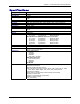
Chapter 1 – Product Description and Specifications Types of Adapters Available Product Adapter Description Region MTS2SA-T Serial-to-Serial + IP (External Power) Global MTS2SA-T-R Serial-to-Serial + IP (RS-232 Power) Global Note: The MTS2SA-T-R (RS-232 Powered) Adapter requires power to be supplied into Pin 6 of the female DB9.
Chapter 1 – Product Description and Specifications Specifications Category Memory Flash Memory Protocols Supported Serial Interface Data Formats Data Rates Flow Control Management Security System Software LEDs Ethernet Power Requirements Operating Temperature Storage Temperature Physical Dimensions Certifications Features Description 8 MEG 2 MEG ARP, DHCP, FTP, HTTP, ICMP, IP, POP3, PPP, SMTP, TCP, Telnet, TFTP, and UDP Standard DCE serial Serial, binary, asynchronous 300; 1200; 2400; 4800; 9600; 19200;
Chapter 1 – Product Description and Specifications Category Software Features Description Internet Applications DHCP Client: Request IP address for Ethernet Interfaces Telnet Server: Command Line Configuration Auto Dial-out Feature Command line via custom port (other than standard port 23) Telnet Client: Connect to remote Telnet Server Serial Auto Dial-in Feature Terminal Server: Network to Serial Connectivity Serial to Network Connectivity TFTP Server: Flash Upgrade SMTP Client: The email client embedded
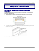
Chapter 2 – Installation Chapter 2 – Installation Attaching the MultiConnect to a Fixed Location The MultiConnect adapter is design to be used on the desktop or to be panel-mounted. To attach the bracket for panel-mounting, following these steps: 1. Typically, the MultiConnect adapter is mounted against a flat surface with two mounting screws. Drill the mounting holes at the desired location. The mounting holes must separated by 4 -7/16 inches center-to-center. 2.
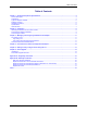
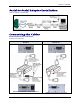
Chapter 2 – Installation Serial-to-Serial Adapter Installation This is an example of a typical setup. Connecting the Cables Serial-to-Serial Power Connections Powered in one of two ways: Powered by External Power Supply MTS2SA-T Adapter RS-232 Connector Powered through RS-232 Cable (Pin 6) MTS2SA-T-R Adapter RS-232 Connector Adapter RS-232 & External Power Connectors Adapter RS-232 Power Pin Connector Multi-Tech Systems, Inc.
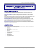
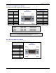
Chapter 2 – Installation Female End of the Multi-Tech Adapter The following tables explain the Multi-Tech Adapter pin functions.
Chapter 3 – Managing and Configuring the MultiConnect Adapter Chapter 3 – Managing and Configuring the MultiConnect Adapter Two Ways to Login Login Using TTY • Use TTY to configure your MultiConnect IP for the first time. Configure the host serial port using the defaults listed below: Baud: 115.2K Data: 8 Parity: N Stop: 1 Flow-Control: None • • Press the Enter key three times to get to the Login prompt or send three carriage returns. At the Login prompt, type admin. At the Password prompt, type admin.
Chapter 4 – Command Line Interface (CLI) Chapter 4 – Command Line Interface and Application Examples See the separate Command Line Interface and Application Examples guide. The guide includes the commands and examples for managing and configuring your MultiConnect Adapter. For your convenience, we have also provided a reference guide of modem AT commands. These guides are available on the MultiConnect CD and on the Multi-Tech Web site. Multi-Tech Systems, Inc.
Chapter 5 – Setting Country or Region Codes Using the CLI Chapter 5 – Setting Country or Region Codes Using the CLI The Default Country or Region Code is B5. If You Want to Change the Country or Region Code, Use the Command Line Interface: Command Syntax Description Default Value Success Error set serial s1 modem country-code value Sets the modem country/region code value to . This command is valid only for port s1. Applicable only if the country-code type is set to code. OK 1.
Chapter 6 – Flash Upgrade Chapter 6 – Flash Upgrade Introduction The MultiConnect Adapter contains a 2 MB flash wherein the boot image, the firmware and configuration files are stored in a compressed format. Serial Flash Upgrade Scenario Following steps explain the procedure to upgrade a flash using the serial COM port (serial flash upgrade). Connect the MultiConnect Adapter to a PC COM Port. • • • • • • • Open an application through which we can access the serial device(e.g., Meterm, zoc, hyperterm).
Appendix A – Regulatory Information Appendix A – Regulatory Information Regulatory Information FCC Part 15 Regulation This equipment has been tested and found to comply with the limits for a Class A digital device, pursuant to Part 15 of the FCC rules. These limits are designed to provide reasonable protection against harmful interference in a residential installation.
Appendix B – Warranty and Service Appendix B – Warranty and Service Multi-Tech Warranty Statement Multi-Tech Systems, Inc., (hereafter “MTS”) warrants that its products will be free from defects in material or workmanship for a period of two, five, or ten years (depending on model) from date of purchase, or if proof of purchase is not provided, two, five, or ten years (depending on model) from date of shipment.
Appendix B – Warranty and Service Repair Procedures for International Distributors International distributors should contact their MTS International sales representative for information about the repairs for their MultiTech product. Please direct your questions regarding technical matters, product configuration, verification that the product is defective, etc., to our International Technical Support department at +(763)717-5863. When calling the U.S.
Index Index A Applications................................................................4 AT Commands .........................................................12 C Command Mode.......................................................11 D Data Mode ...............................................................11 E EMC, Safety, and Directive Compliance ..................15 F Flash Upgrade Scenario 1 .......................................14 H Handling Precautions .......................................