SmartServer 2.
Echelon, i.LON, LON, LONWORKS, LonTalk, Neuron, LONMARK, 3120, 3150 and the Echelon logo are trademarks of Echelon Corporation registered in the United States and other countries Other brand and product names are trademarks or registered trademarks of their respective holders.
Table of Contents FCC Compliance Statement – Class B ................................................................ vi IC Compliance Statement – Class B ............................................................. vi VCCI Compliance Statement – Class B ITE.................................................. vi Welcome .......................................................................................................... vii Purpose ........................................................................
iv Preface
Preface Echelon’s SmartServer is a low-cost, high-performance controller, network manager, router, remote network interface, and Web server that you can use to connect LONWORKS®, BACnet, Modbus, and M-Bus devices to corporate IP networks or the Internet. SmartServer 2.
FCC Compliance Statement – Class B This equipment has been tested and found to comply with the limits for a Class B digital device pursuant to Part 15 of the FCC Rules. These limits are designed to provide reasonable protection against harmful interference in a residential installation. This equipment generates, uses, and can radiate radio frequency energy and, if not installed and used in accordance with the manufacturer’s instruction manual, may cause interference with radio communications.
Welcome The SmartServer is a low-cost, high-performance controller, network manager, router, remote network interface, and Web server that you can use to connect LONWORKS, BACnet, Modbus, and M-Bus devices to corporate IP networks or the Internet. You can connect the SmartServer to a LONWORKS TP/FT-10 channel using the LON connections on the hardware. You can connect the SmartServer to a PL-20 LONWORKS channel through the high-voltage 100/240V AC mains connection.
72102R-440 (FT) x x 72103R-440 (PL) x x 72103R-460 (PL) External coupling x x x Note: You can order programmability and IP-852 activation keys for units that do not have these options pre-installed. Box Contents The SmartServer 2.2 hardware ships with the following material: • SmartServer 2.2 DVD. This DVD contains the Echelon SmartServer 2.2 software, Echelon Programming Tools Demo, Echelon Enterprise Services, Echelon i.
• SmartServer 2.2 Power Line Repeating Network Management Guide. Describes how to install a PL-20 repeating network and how to use the SmartServer to prepare, maintain, monitor and control, and connect the network. • SmartServer 2.0 Programmer’s Reference. Describes how to configure the SmartServer using XML files and SOAP calls. This allows you to create your own applications that you can use to configure, monitor, and control the SmartSever. • SmartServer 2.2 Quick Start Guide.
You can also view free online training or enroll in training classes at Echelon or an Echelon training center to learn more about developing devices. You can find additional information about device development training at www.echelon.com/training. You can obtain technical support via phone, fax, or e-mail from your closest Echelon support center. The contact information is as follows (check www.echelon.
Region Korea Languages Supported Korean Other Regions English SmartServer 2.2 Hardware Guide Contact Information Echelon Korea #505 JPLUS Tower 164-3 Samsung-Dong, Gangnam-Gu Seoul 135-881 Republic of Korea Phone: +82 2 568 2783 Fax: +82 2 566 1483 support@echelon.com.kr Phone: +1.408-938-5200 Fax: +1.408-328-3801 lonsupport@echelon.
xii Preface
1 Assembling the SmartServer Hardware This chapter describes how to mount the SmartServer hardware inside a suitable enclosure. It describes how to connect the SmartServer hardware to a power supply; LONWORKS FT-10 and PL-20 channels; digital input, digital output, and pulse meter input devices; and TCP/IP networks. It describes how to connect the SmartServer console port to access its console application. SmartServer 2.
Assembly Overview You need to mount the SmartServer and connect it to an IP network before you can configure it and begin using its embedded applications. This section lists the general steps required to mount and connect the SmartServer. These steps are then detailed in the referenced sections. 1. Mount the SmartServer inside a suitable enclosure. For more information on this step, see the next section, Mounting the SmartServer. 2. Connect the screw terminals on the SmartServer. a.
b. Open a W browser and enter the following URL: 192.168.1.222. Your SmartServer home page opens. c. Click the Login button. A login dialog appears. Enter ilon for both the User Name and the Password and then click OK. The SmartServer 2.2 – Welcome Web page opens. You can configure your SmartServer and begin using its embedded applications as described in the SmartServer 2.2 User’s Guide. d.
4 Assembling the SmartServer Hardware
Wiring the SmartServer Connections After you mount the SmartServer, you can wire its connections. The SmartServer has two rows of screw terminals, an RJ-45 10/100 Base T Ethernet port, a DB-9 console port, and an RJ-11 telephone line (SmartServer models 72102). You must connect the power screw terminals for all SmartServer models as described in the Power Supply section.
Connecting the Screw Terminals The SmartServer has two rows of screw terminals located on the top and bottom edges of the enclosure. The screw terminals on the bottom row are numbered 1 to 12 (from left to right), and the screw terminals on the top row are numbered 13 to 28 (from right to left). There is no polarity for DC connections. The screw terminals accept 0.22mm – 3.3mm (22 – 12AWG) gauge solid wire. The optimum tightening torque for the screw terminals is 0.75 Newton-meters (6 lbs. in.) maximum.
! Safety Warning The SmartServer uses a Poly-carbonmonoflouride Lithium Coin battery. THERE IS A RISK OF EXPLOSION IF THE BATTERY IS REPLACED BY AN INCORRECT TYPE. DISPOSE OF UNUSED BATTERIES ACCORDING TO THE INSTRUCTIONS. ! Safety Warning The SmartServer is not equipped with a power disconnect device. When the device is installed and mounted, the installer must provide a means to safely remove power, such as a power switch or a circuit breaker.
The following table lists the enclosure marking for each of the high-voltage AC power mains screw terminals and their connection type. Screw Terminal Enclosure Marking Mains Connection 1 E Earth ground 2 NC Do not connect 3 N Neutral 4 L Line ! Safety and High Voltage Warning Ensure that the AC power mains are turned OFF before removing the cover, handling the mains wiring, or connecting any power mains cabling to the SmartServer device.
! Sicherheitshinweis: Vorsicht Netzspannung! Stellen Sie sicher, daß die Netzspannung ausgeschaltet wurde (Schalterstellung OFF), ehe der Gehäusedeckel entfernt, an der Spannungsversorgung hantiert oder irgendeine Netzverbindung mit dem SmartServer Gerät hergestellt wird. AUF KEINEN FALL darf das SmartServer mit Netzspannungen ausserhalb des Bereichs 100/240V, -10% bis +30%, 50/60Hz±2.5Hz betrieben werden.
The following table lists the enclosure markings for the LONWORKS network screw terminals on the SmartServer and their connection type. Screw Terminal Enclosure Marking ® LONWORKS Network Connection 17 LON B/PLT + TP/FT-10 twisted pair 18 LON®A/PLT - TP/FT-10 twisted pair RS-232/RS-485 Serial Ports The SmartServer includes one RS-232 serial port and one isolated RS-485 multi-drop bus port. The RS-232 serial connection is implemented on screw terminals 21–25.
The following table lists the enclosure markings for the RS-232 and RS-485 port screw terminals and on the SmartServer and their connection types.
Notes: If your external GSM modem requires a carrier detect line, you can attach one end of a 22-gauge (AWG) stranded wire to the carrier detect port on your modem, and then connect the other end of the wire to pin 1 of the RS-232 console port on the SmartServer. If you are connecting an external GSM modem that uses a wireless antenna to your SmartServer, you must install the modem at least 1m away from the SmartServer.
and RS-485 serial ports, and use a custom driver for communication between the SmartServer and the devices over the RS-232 or RS-485 serial interfaces. You can create custom drivers for your SmartServer with Echelon SmartServer Programming Tools. A demo version of the Echelon SmartServer Programming Tools is available on the SmartServer 2.2 DVD. To build custom drivers and deploy them on your SmartServer, order the Echelon SmartServer Programming Tools DVD.
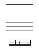
You can connect the dry contact relay outputs on the SmartServer to a voltage source and a load. When an ON value is asserted, the circuit will be closed and the voltage source will drive the load. The following figure demonstrates this configuration. 5 6 7 8 Switched DC + Switched AC Line DC + AC Line Voltage Source DC AC Neutral Resistive Load Inductive loads such as motors, relays, or contactors present a special case for the SmartServer relay contacts.
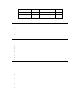
5 6 DC + 7 8 Switched DC + DC Voltage Source Load Resistor DC - - Control + SSR Output AC Line Switched AC Line AC Voltage Source AC Neutral Inductive Load Pulse Meter Inputs The SmartServer includes two impulse meter inputs that comply with the DIN 43 864 impulse standard (open terminal voltage <12VDC, maximum current ≤27mA). The pulse meter input connections are implemented on screw terminals 9–12: Meter 2 is connected to terminals 9-10; Meter 1 is connected to terminals 11-12.
The following table lists the enclosure markings for the pulse meter input screw terminals on the SmartServer and their connection type.
Digital Inputs The SmartServer has two optically isolated, polarity-sensitive digital inputs that you can use to monitor switch and sensor devices. The digital input connections are implemented on screw terminals 13–16: Input 2 is connected to terminals 13-14; Input 1 is connected to terminals 15–16. These connections are polarity-sensitive: terminals 14 and 16 are marked positive (+), and terminals 13 and 15 are marked negative (-).
+12V <20mA Output Digital Input Connectors +12V < 20mA Output The SmartServer contains one +12VDC outlet that can provide up to 20mA. The +12V <20mA output is available on screw terminals 19 and 20. Screw terminal 20 is the +12V <20mA connection. Screw terminal 19 is the system ground. You can connect the +12V <20mA output on the SmartServer to a set of dry contacts in order to power an active device that is connected to the digital input screw terminals.
Connecting the Ethernet Port After you have connected all the required screw terminals on the SmartServer for your system, you can connect the RJ-45 10/100 BaseT Ethernet on the SmartServer to an Ethernet switch or hub that can communicate with your computer. This will connect the SmartServer to an IP network, and enable you to configure the SmartServer with its built-in Web pages.
Connecting the Telephone Line Port ! Safety Warning The SmartServer’s telephone modem must only be used with telephone circuits equipped with proper lightning and transient protection circuitry. This minimizes the risk of shock or damage should lightning strike on or near a telephone circuit to which the SmartServer is connected. For SmartServer models 72102, which contain a 56K V.90 analog modem, you can connect the RJ-11 telephone line port.
2 Using the SmartServer LEDs and Buttons This chapter describes how to use the LEDs and buttons on the SmartServer hardware. SmartServer 2.
Using the SmartServer LEDs The SmartServer has a number of LEDs that provide status information. The following figure and table display and describes these LEDs. Power/Wink Lights when the SmartServer has power. When the SmartServer receives a LONWORKS wink command, this LED blinks on and off 5 times. When the SmartServer’s applications are not running, this LED blinks rapidly. Service Indicates the state of the LonTalk interface in the SmartServer. This LED is normally off.
For PL models of the SmartServer, this LED is the Band In Use (BIU) indicator. It lights whenever there is a signal present on the band that is greater than 80dBµVrms (between 131.5kHz and 133.5kHz). If this LED is on, the SmartServer cannot transmit LONWORKS data. LON BIU/RX For FT models of the SmartServer, this LED is the receive transmission (RX) indicator. It lights when the SmartServer receives LONWORKS data. For PL models of the SmartServer, this is the Packet Detect (PKD) indicator.
shortcut menu. The Setup – Reboot dialog opens. Click Reboot to start the reboot. • To reboot your SmartServer using the console application, enter the reboot command. For more information on using the SmartServer Web pages and the console application to reboot the SmartServer, see the SmartServer 2.2 User’s Guide.
www.echelon.