
Instruction manual


Wiring the SmartServer Connections
After you mount the SmartServer, you can wire its connections. The SmartServer has two rows of
screw terminals, an RJ-45 10/100 Base T Ethernet port, a DB-9 console port, and an RJ-11 telephone
line (SmartServer models 72102).
You must connect the power screw terminals for all SmartServer models as described in the Power
Supply section. If you are assembling an FT-10 model of the SmartServer, yo u must connect a
L
ONWORKS TP/FT-10 channel to t he LON A
®
and LON B
®
screw terminals (17 and 18). Optionally,
you ca n connect the other screw terminals on the SmartServer (the RS-232/RS-485 serial ports, digital
outputs, pulse meter inputs, d igital input s, a nd the +12V <20mA output).
After you connect the screw terminals, if you are not using an internal analog modem use an Ethernet
cable to connect the Ethernet port on the SmartServer to an IP network. This enables you to c onfigure
the SmartServer using its built-in Web pages and begin using its embedded applications. Optionally,
you can connect the console port on the SmartServer so that you can use the SmartServer console
application to configure the SmartServer.
If you are using an int ernal modem, wire the RJ-11 telephone port on the SmartServer to an analog
phone line.
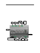
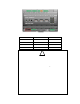
The following figure illustrates the locatio n of all the SmartServer connections.
Service Pin
RS-485
Serial
RS-232
Serial
+12V
<20 mA
LON
WORKS
Digital
Inputs
RJ-45 10/
100 Base
T Ethernet
Port
Reset Switch
High-Voltage
(100-240 VAC, 50/60 Hz)
Relay
Outputs
DB-9
Console Port
RJ-11
Telephone
Line Port
Pulse Meter
Inputs
SmartServer 2.2 Hardware Guide 5