
Instruction manual


Connecting the Screw Terminals
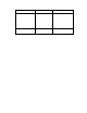
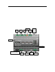
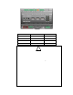
The SmartServer has two rows of screw terminals located on the top and bottom edges of the
enclosure. The screw terminals on the bottom row are numbered 1 to 12 (from left to right), a nd the
screw terminals on the top row are numbered 13 to 28 (from right to left). The re is no polarity for DC
connections.
The screw terminals accept 0.22mm – 3.3mm (22 – 12AWG) gauge solid wire. The optimum
tightening torque for the screw terminals is 0.75 Newton-met ers ( 6 lbs . in.) maximum. The ideal
flathead screwdriver tip width for use with the screw terminal connectors is 3mm (0.12”). Strip wires
to a length of 7mm (0.28”). Optio nal l y, yo u can use a so ldering iron to tin the stripped lengths of any
stra nded wires to prevent fraying and ina dvertent contact with adjacent terminals.
The screw terminals are divided into the following groups, which are each detailed in the subsequent
sections.
• Power supply
• L
ONWORKS network
• RS-232/RS-485 serial ports
• Digital outputs
• Pulse mete r inputs
• Digital inputs
• +12V<20mA output
Power Supply
The SmartServer is powered by a 100/240V AC, -6% to +10%, 50/60Hz VAC power mains
connection.
!
Safety Warning
When connecting a unit, always co nnect ear t h ground fi rst, then Neutral, and then Line .
Thi s mini mizes the risk o f shock or damage should power inadverte ntly be present on
Line.
!
Safety Warning
Fuse F350 in the SmartServer uses a Wickmann rated 250 VAC, .5 A, SLO-BLO fuse,
and it is not field rep la c e a ble.
6 Assembling the SmartServer Hardware