
Instruction manual
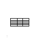
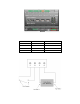


The following table lists the enclosure markings for the L
ONWORKS network screw terminals on the
SmartServer and their connection type.
Screw Terminal
Enclosure Marking
L
ON
W
ORKS
Network Connection
17
LON
®
B/PLT +
TP/FT-10 twisted pair
18
LON
®
A/PLT -
TP/FT-10 twisted pair
RS-232/RS-485 Serial Ports
The SmartServer includ es one RS-232 serial port and one isolated RS-485 multi-drop bus port. The
RS-232 serial connection is implemented on screw ter minals 21–25. These connections are
polarity-sensitive. You can connect an external GSM modem, M-Bus devices, Modbus devices, or
legacy/nonnative devices (requires a custom driver) to the RS-232 serial port. The RS-232 serial port
supports only one device at a time.
The RS-485 bus connection is implemented on screw terminals 25–28. These connections are
polarity-sens itive: terminal 28 is marked positive (RT+) , and ter minal 27 is marked negative (RT-).
Do not reverse the polarity of the RS-485 port will because it will cause improper bus operation. The
RS-485 port picks up ground at terminal 25. T he RS-485 connect i on is not susceptible to common
mode ground differential voltage swin gs, but you must use a suitable shielded cable when connecting
devices in noisy environme nt s. You can connect Modbus devices or legacy/nonnative devices (requires
a custom driver) to the RS-485 port.
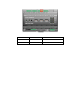
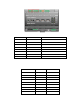
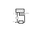
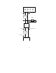
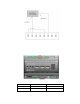
The following figure illustrates the locatio n of the RS-232 and RS-485 screw terminals on the
SmartServer.
10 Assembling the SmartServer Hardware